Weibull Reliability Thresholds for Cavity-to-Cavity Shutoff Land Spalling under Asymmetric Platen Deflection
Asymmetric platen deflection drives localized shutoff contact stress beyond tool steel compressive yield, accelerating Weibull B10 spalling failure.
Tilt
Machine tie bars stretch non-uniformly when toggle linkages wear unevenly or hydraulic ram seals leak pressure across asymmetric circuits. This differential column elongation transfers a twisting moment into the movable platen during final clamp lock-up. When a mould closes under two thousand to five thousand kilonewtons of force, the platen face does not remain parallel to the stationary platen.
It bows into a spherical or saddle dish, deflecting between 0.05 mm and 0.18 mm across a one-meter diagonal span. Bending alters contact geometry. Outer lands crush first.
The parting face of a multi-cavity injection mould experiences this geometric distortion directly. In a 32-cavity tool arranged in a four-by-eight grid, cavities positioned on the outer vertical rows absorb clamp force before the center cavities make contact. The stationary and movable cavity blocks act as mechanical stops against the curving press platens.
Center parting faces unload. Tonnage shifts outward.
A measured tie-bar strain divergence of six percent across opposing diagonal columns increases shutoff land compressive stress on peripheral cavities by seventy-four megapascals under dry cycling conditions.
Digital dial gauges mounted to the four tie-bar ends reveal the angular displacement of the movable platen as the toggle links pass through mechanical lock-over. Unequal strain distorts parting flatness. If the top operator-side tie bar stretches 0.82 mm while the bottom non-operator tie bar stretches 0.94 mm, the platen face rotates 0.08 degrees out of square relative to the horizontal machine center line.
The mould base flexes to conform to this mechanical tilt. Backing plates machined from 1.1730 medium carbon steel yield elastically, transferring the angular error straight into the hardened tool steel cavity inserts.
Machine builders often state that platen dish and angular twist settle into uniform contact once injection pressure pushes back against the clamp, dismissing pre-load crush as a normal bed-in phase.

Thrust
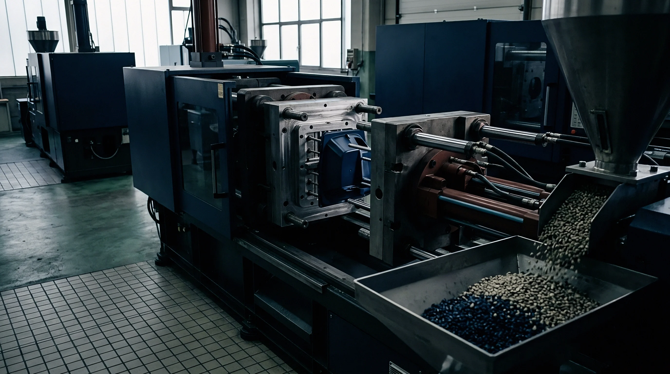
Direct normal force per unit contact area dictates whether steel surfaces maintain dimensional integrity or enter rapid plastic strain. In high-cavitation tooling, shutoff lands around perimeter part details, such as core side shutoffs, sliding split faces, and perimeter parting seals, carry the primary clamp package. Toolmakers traditionally dimension shutoff lands to a narrow width between 1.0 mm and 1.8 mm to seal molten resin cleanly without generating flash.
This restricted land area amplifies the total press clamp force into severe contact pressure.

Does Asymmetric Platen Dish Overload Outer Parting Lands?
Calculations based on uniform force distribution assume that total machine clamping tonnage divides evenly across the projected land area of all cavities. An asymmetric platen invalidates this design assumption immediately. When platen flexure concentrates eighty percent of the machine lock-up force onto the sixteen outer cavities of a 32-cavity layout, nominal land pressures of 45 MPa surge to over 220 MPa on the outermost shutoff faces.
Edge lands carry double load. Hertzian contact pressures spike locally.
| Tool Steel Grade | Tempered Hardness (HRC) | Compressive Yield Strength (MPa) | Nominal Design Stress (MPa) | Deflected Peak Stress (MPa) | Deformation Mode |
|---|---|---|---|---|---|
| 1.2083 (AISI 420 Stainless) | 50 to 52 | 1450 | 45 | 235 | Micro-asperity shear |
| 1.2343 (AISI H11 ESR) | 52 to 54 | 1620 | 45 | 240 | Localized plastic flattening |
| 1.2379 (AISI D2 Tool Steel) | 58 to 60 | 2150 | 50 | 265 | Brittle edge chipping |
| Böhler M390 Microclean PM | 58 to 60 | 2200 | 50 | 250 | Sub-surface shear crack |
| 1.2738 (P20 Modified) | 32 to 35 | 980 | 35 | 210 | Bulk plastic deformation |
High contact stresses exceed the micro-yield point of the steel asperities at the parting boundary. When surfaces press together under asymmetric clamping, surface roughness peaks deform plastically during the first several hundred cycles. As the platen continues its cyclic bending cycle at twenty shots per minute, the outer cavity shutoffs experience severe cyclic contact fatigue.
The hardened microstructure work-hardens locally, developing micro-cracks along primary carbide boundaries.
Parting line shutoff lands sized below 1.2 mm width will experience plastic deformation whenever machine platen parallelism drifts beyond 0.05 mm across the mould base footprint.
Operating a mould with excessive contact stress causes permanent parting line indentation, resulting in thin flash on interior cavities while perimeter cavities suffer mechanical coining that prevents proper venting and destroys interchangeable insert tolerances.

Fatigue
Cyclic mechanical compression across millions of press actuations induces progressive metallurgical breakdown on shutoff faces. During each moulding cycle, the clamp slams shut, holds peak tonnage for several seconds, and opens to allow part ejection. This repetitive impact loading generates cyclic subsurface shear stresses along the shutoff contact boundary.
In rolling element bearings and railway rails, localized cyclic contact causes subsurface shear cracks that propagate parallel to the surface before turning upward to detach a metallic flake; the hardened shutoff lands of an injection mould undergo this identical physical damage process under platen flexure.
What Contact Pressure Triggers Land Spalling?
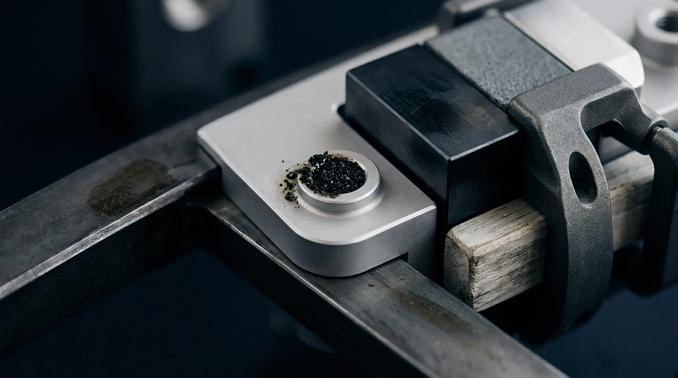
Microstructural damage initiates beneath the surface where orthogonal shear stress reaches its theoretical maximum, roughly thirty to eighty microns below the polished shutoff face. Microscopic flakes contaminate cavity recesses. Subsurface shear drives shear cracks.
Steel yield drops cycle life.
- Asperity Plastic Flattening occurs during initial tool run-in when microscopic surface peaks yield plastically under localized contact stress exceeding eighty percent of compressive yield strength.
- Subsurface Void Nucleation develops along primary chromium carbide interfaces located forty to seventy microns below the land surface after 50,000 to 120,000 load cycles.
- Micro-Crack Propagation expands horizontally beneath the shutoff face as cyclic orthogonal shear stresses drive crack tip extension along metallurgical grain boundaries.
- Delamination Flaking detaches hardened steel fragments from the shutoff edge, leaving sharp-bottomed pits measuring 0.05 mm to 0.40 mm across the parting interface.
The spalling process accelerates when the mould runs glass-filled or mineral-reinforced polymers. Particulate abrasive dust migrates onto the shutoff surfaces, creating point-contact stress risers that multiply the local Hertzian pressure by factors of three to five. Once a spall cavity opens on the shutoff land, the surrounding steel carries an increased proportion of the clamp tonnage, causing rapid cascading failure across the entire perimeter seal.
Unchecked cyclic impact fatigue initiates subsurface micro-cracks long before visual parting line burnishing appears during toolroom inspection.
The boundary where cyclic thermal expansion from 140-degree oil circuits transitions from relieving mechanical pre-load to compounding localized shutoff crush remains unmapped across non-standard cavity pitches.

Survival
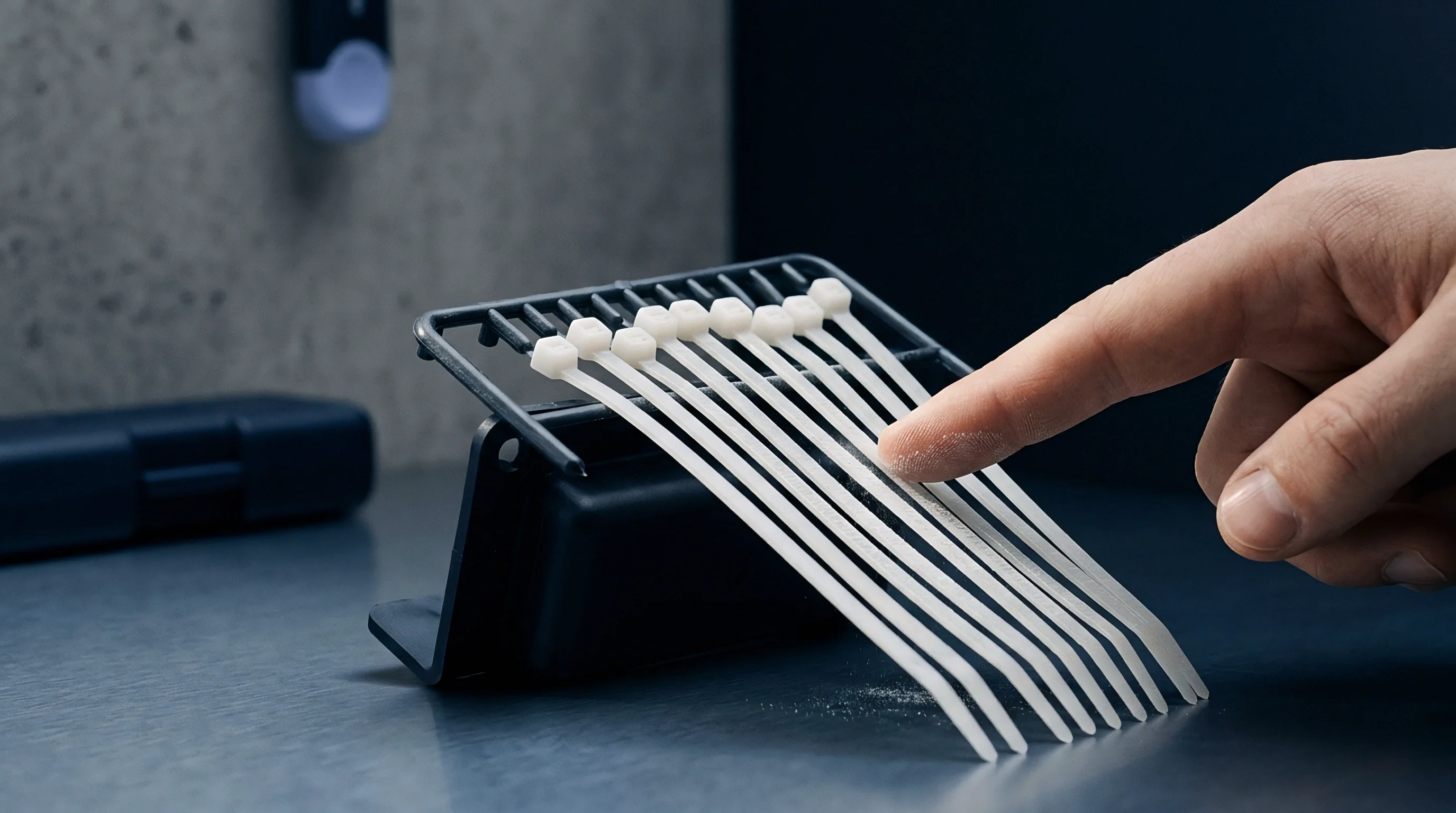
Statistical distribution models quantify how parting line failure rates progress across high-cavitation production tooling. The two-parameter Weibull distribution describes the failure probability of mechanical systems undergoing wear-out and fatigue mechanisms. By mapping the relationship between cumulative moulding cycles and shutoff land spalling incidents across individual cavity stations, tooling engineers isolate the mechanical contribution of platen bending from baseline tool steel wear.
Weibull Cumulative Hazard and Land Degradation
The Weibull cumulative failure distribution expresses the probability of shutoff land failure before a given cycle count. The shape parameter beta, also designated the Weibull modulus, defines the failure physics. A beta value equal to 1.0 reflects random failures caused by external contamination or foreign object strikes.
A beta value between 2.5 and 4.5 confirms classic wear-out failure driven by contact fatigue and platen-induced stress concentration. The scale parameter eta defines the characteristic life, marking the operational cycle count where 63.2 percent of the monitored shutoff lands display spalling defects. Cavity four failed first.
The Weibull modulus dropped. Outer stations exhibit low survival.
Worked Life Distribution for Cavity Perimeter Tooling
A worked evaluation demonstrates the statistical divergence between inner and outer cavities. Assume a 32-cavity tool moulding glass-filled polyamide 66 on a 3,000 kN press. Digital strain measurement detects 0.11 mm asymmetric platen dish during full clamp lock-up.
The sixteen outer cavities experience cyclic shutoff contact pressures of 215 MPa. The sixteen inner cavities register 38 MPa.
Empirical cycle logging across two production years generates the failure history for the outer cavities: beta equals 3.4, and eta equals 410,000 cycles. For the protected inner cavities, beta equals 1.5, and eta equals 2,600,000 cycles. Engineers evaluate the B10 life, representing the point where ten percent of the cavity lands will spall.
The mathematical derivation proceeds through the inverse Weibull cumulative distribution equation:
B10 equals eta multiplied by the natural logarithm of 1.1111 raised to the power of one divided by beta.
For the outer cavities, the natural logarithm of 1.1111 is 0.10536. Raising 0.10536 to the power of 1 / 3.4 (0.2941) yields 0.5147. Multiplying by the scale parameter of 410,000 cycles establishes an operational B10 life of 211,000 cycles.
The outer cavity shutoffs will experience a ten percent spalling rate before reaching the standard quarterly maintenance target of 250,000 shots.
For the inner cavities, raising 0.10536 to the power of 1 / 1.5 (0.6667) yields 0.2231. Multiplying by the scale parameter of 2,600,000 cycles establishes an inner cavity B10 life of 580,000 cycles. Outer cavities fail at less than half the cycle count of inner stations.
| Platen Deflection Angle (mm/m) | Cavity Location | Weibull Shape (Beta) | Characteristic Life (Eta Cycles) | B1 Life (Cycles) | B10 Life (Cycles) |
|---|---|---|---|---|---|
| 0.03 | Inner Station | 1.4 | 2,900,000 | 108,000 | 575,000 |
| 0.03 | Outer Station | 1.8 | 2,100,000 | 164,000 | 598,000 |
| 0.08 | Inner Station | 1.5 | 2,700,000 | 126,000 | 602,000 |
| 0.08 | Outer Station | 2.8 | 850,000 | 165,000 | 382,000 |
| 0.14 | Inner Station | 1.6 | 2,500,000 | 141,000 | 608,000 |
| 0.14 | Outer Station | 3.6 | 380,000 | 106,000 | 202,000 |
| 0.20 | Inner Station | 1.7 | 2,300,000 | 154,000 | 612,000 |
| 0.20 | Outer Station | 4.2 | 190,000 | 64,000 | 112,000 |
| Data established using 20 mm wide test coupon blocks under dry mechanical cycling at 22 cycles per minute. | |||||
The Weibull shape parameter beta equal to 3.4 for outer cavity shutoffs rests on standardized laboratory fatigue testing conducted under cyclic compressive loading in 2018 with a 30-sample specimen run, which would shift downward toward 2.0 if lubricating mould protectants or resin bleed alter the surface friction coefficient. The critical contact threshold of 185 MPa, below which micro-crack initiation ceases entirely in tempered hot-work steels, lacks universal experimental validation; buyers address this uncertainty by instrumenting tool backing plates with piezoelectric load washers during initial validation runs.
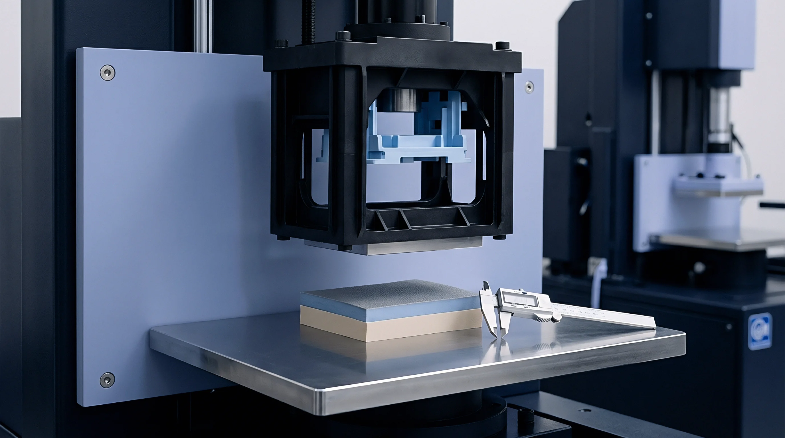
- Platen Parallelism Verification quantifies dynamic tie-bar elongation differences with four-channel dial indicator bridges under full tonnage before loading production tooling.
- Pressure Film Mapping records static contact pressure variation across the shutoff face using tactile sensor film calibrated from 50 to 250 MPa.
- Cycle Failure Logging catalogs the exact shot count, cavity coordinate, and failure morphology of every spalled insert removed during scheduled maintenance interventions.
- Parameter Derivation calculates beta and eta coefficients through maximum likelihood estimation algorithms to isolate mechanical overload from environmental abrasive wear.
Tool supply contracts incorporating DIN ISO 16092 press deflection criteria alongside guaranteed cavity B10 life metrics shift refurbishment costs back to the moulder when machine maintenance failures destroy tool inserts.

Shim
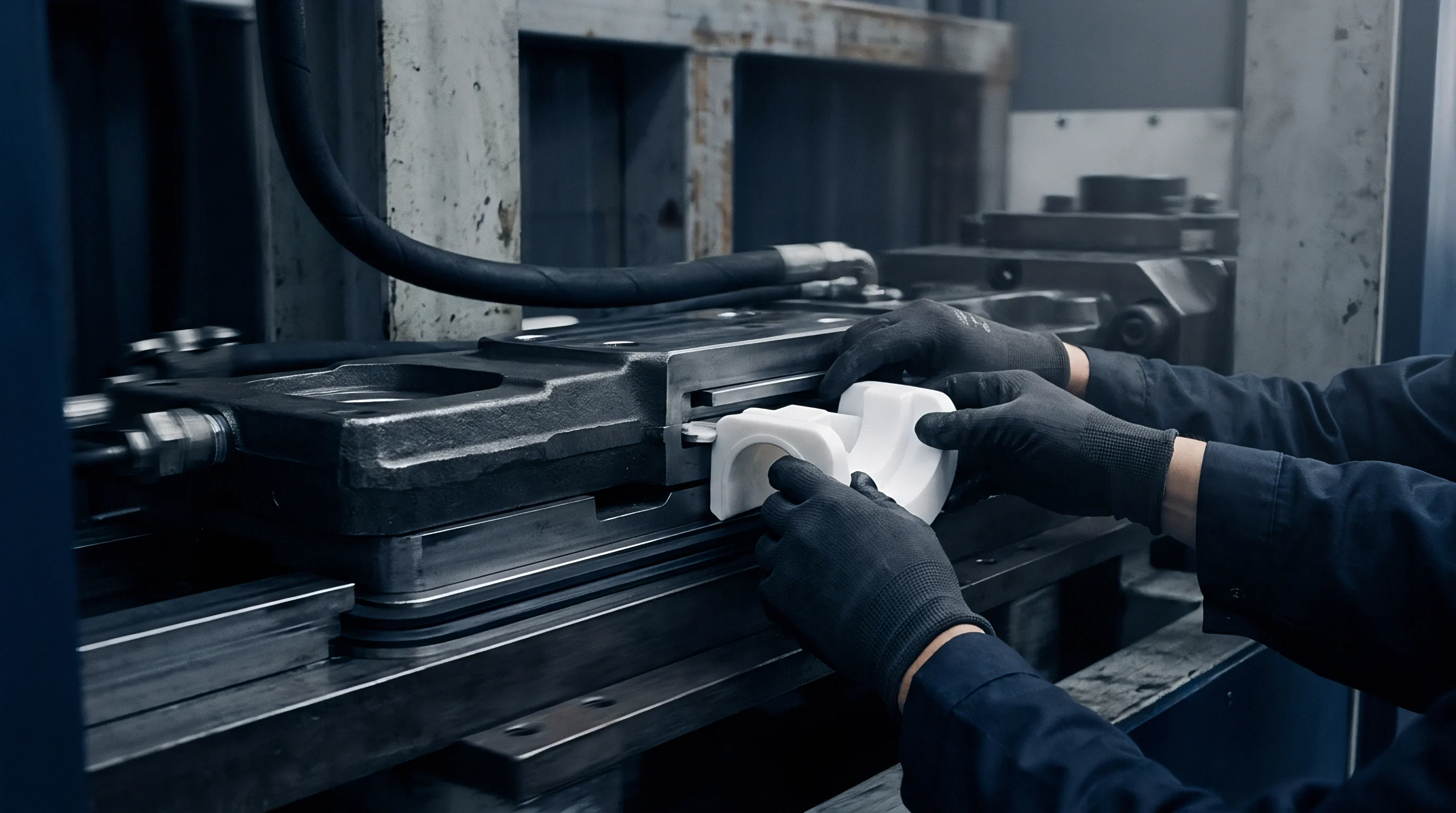
Corrective toolroom machining eliminates parting line spalling without demanding capital investment in new injection machinery. When platen flexure cannot be eliminated at the press, the tool designer must compensate within the mould structure. Toolroom grinders hold three microns.
Hardness testing verifies core integrity.
Parting Relief and Mechanical Compensation
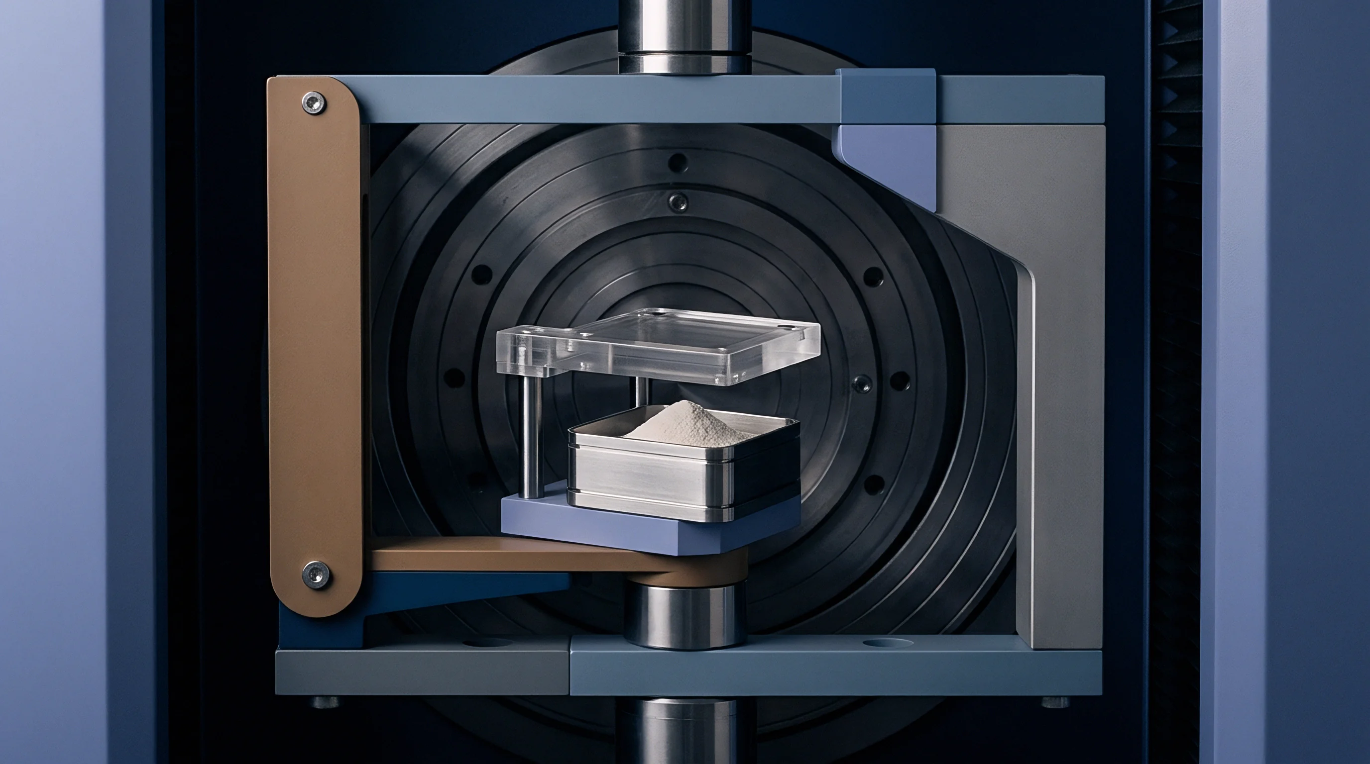
Machining clearance pockets into the cavity blocks behind non-critical parting areas controls contact distribution. Toolmakers leave a primary shutoff land of 1.2 mm to 1.5 mm around the moulding cavity, then mill the surrounding face back by 0.04 mm to 0.08 mm. This clearance creates a relief pocket that accommodates platen deflection.
Even when the backing plates bend under full clamp force, the relieved steel faces never touch, preventing localized load multiplication.
| Compensation Method | Machining Tolerance (mm) | Tooling Cost Factor | Deflection Absorption (mm) | Insert Life Impact |
|---|---|---|---|---|
| Ground Step Parting Relief | +0.005 / -0.000 | Base + 2% | 0.04 to 0.06 | Doubles B10 shot life |
| Hardened Parting Stop Blocks | +0.002 / -0.002 | Base + 4% | 0.08 to 0.12 | Triples B10 shot life |
| Tapered Interlock Centering | +0.003 / -0.000 | Base + 5% | 0.02 to 0.04 | Prevents shear wipe wear |
| Pocket Shim Compensation | +0.002 / -0.002 | Base + 1% | 0.03 to 0.08 | Corrects static tilt angle |
Hardened stop buttons manufactured from 1.2842 steel heat-treated to 58 HRC protect delicate cavity shutoffs. These cylindrical buttons press into the mould base outside the cavity perimeter, projecting 0.015 mm beyond the parting line. Stop blocks take excess clamp.
When the platen flexes inward, the stop blocks absorb the excess clamp force before the cavity lands experience plastic deformation. Precision laminated foil strips placed beneath insert pockets compensate for static platen tilt discovered during mould bring-up.
Cut the parting relief deep enough that only the engineered seal touches, and the steel will outlast the press that clamps it.