Transient Heat Transfer Calculations for Injection Mold Cooling Design
Transient cooling calculations govern injection mold cycle times, where resin thermal diffusivity and steel channel turbulence dictate part yield and warpage.

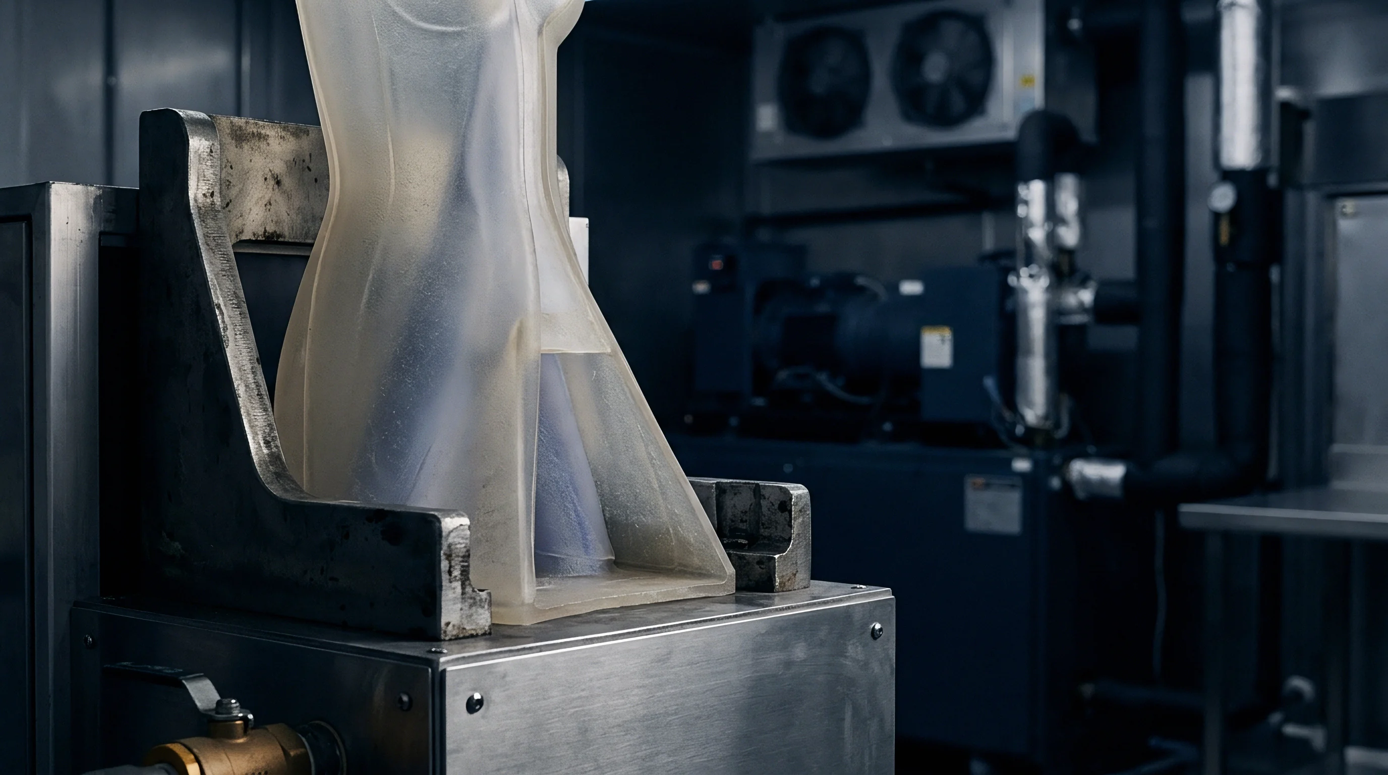
Flux
Heat removal fixes cycle duration and part geometry across every injection cycle. A standard high-pressure injection press cycling a crystalline polyolefin delivers melt into the cavity steel between 200 and 240 degrees Celsius, holding pack pressure until the gate freezes, before opening once the thickest section drops below the ejection temperature of 90 degrees Celsius. That thermal transition represents roughly eighty percent of total cycle duration.
Tooling quotes frequently compress this window to show attractive machine-hour rates. The quoted cycle of fourteen seconds slips to twenty-two seconds during tool bring-up whenever the cooling calculation ignores transient conduction resistance inside the cavity steel and polymer slab.
Energy leaves the injected polymer through transient conduction across the frozen skin, crosses the interface resistance into the cavity wall, disperses through the tooling block, and leaves via convective turbulent flow in drilled water lines. Fourier’s field equation describes this unsteady thermal migration within the resin core:
∂T/∂t = α (∂²T/∂x²)
The variable α defines thermal diffusivity, calculated from thermal conductivity k divided by the product of density ρ and specific heat capacity Cp. Semicrystalline resins introduce latent heat of crystallization across the solidification band. Latent enthalpy acts as a localized heat source, delaying internal temperature drop compared to purely amorphous resins. Tool designers evaluating cycle times without accounting for latent heat underpredict required cooling durations by fifteen to thirty percent.
Unsteady conduction through the resin slab commands seventy to eighty-five percent of overall thermal resistance across standard injection wall sections.
Calculating the cooling phase requires explicit definition of part wall thickness, melt injection temperature, mold base interface temperature, and allowable part ejection temperature. When the part wall thickens by twenty percent, required cooling time increases by roughly forty-four percent because conduction time scales with the square of part thickness. Designers often assume mold metal surfaces remain isothermal throughout the cycle.
Steel cavity wall temperatures fluctuate cyclically by five to twenty-five degrees Celsius every shot, altering actual thermal flux across the boundary.
The operational consequence of this thermal mismatch lands directly on the toolmaker bench through warpage, differential shrinkage, and post-ejection sink marks.


Resistance
Transient energy transfer from polymer core to chiller return encounters three distinct, coupled thermal resistances. The polymer resistance varies continuously over time as the liquid core freezes into a solid layer. The boundary resistance between plastic and tool steel changes dynamically as packing pressure decays into volumetric shrinkage.
The internal conduction resistance through the tool steel block remains constant, terminating at the convective boundary inside the cooling channel bore.

Thermal Resistance Decomposition
Analyzing thermal dissipation as a series circuit reveals the rate-limiting steps across the injection cycle. Polypropylene possesses a thermal conductivity of approximately 0.15 to 0.22 Watts per meter-Kelvin. P-20 tool steel conducts heat at 29 Watts per meter-Kelvin, while beryllium copper alloys reach 130 Watts per meter-Kelvin.
Heat stalls inside the plastic wall. Even with chilled coolant flowing at high velocity, energy extraction cannot bypass the low conductivity of the solidifying polymer shell.
| Material Class | Designation | Thermal Conductivity (W/m·K) | Specific Heat (J/kg·K) | Thermal Diffusivity (10⁻⁶ m²/s) |
|---|---|---|---|---|
| Tool Steel | AISI P-20 | 29.0 | 460 | 8.05 |
| Tool Steel | AISI H-13 | 24.5 | 460 | 6.80 |
| Stainless Tool Steel | AISI 420 (1.2083) | 20.0 | 460 | 5.55 |
| Copper Alloy | MoldMAX HH (BeCu) | 131.0 | 380 | 41.20 |
| Semicrystalline Resin | PP Homopolymer | 0.18 | 2100 | 0.095 |
| Semicrystalline Resin | PA66 (Unfilled) | 0.24 | 2200 | 0.098 |
| Amorphous Resin | ABS (Medium Impact) | 0.17 | 1500 | 0.108 |
| Amorphous Resin | PC (Unfilled) | 0.20 | 1250 | 0.133 |

Interface Gap Mechanics
Molten polymer contacts cavity steel under injection pressures ranging from 600 to 1400 bar during the fill and pack stages. High pack pressure forces intimate micro-contact between resin and tool asperities, yielding an interfacial heat transfer coefficient exceeding 1500 Watts per square meter-Kelvin. Cavity pressure bleeds down as the gate seals and melt cools.
Volumetric shrinkage pulls the freezing shell away from the tool cavity surfaces.
An air gap forms along cavity faces where draft angles permit separation, reducing the interface heat transfer coefficient to values between 150 and 300 Watts per square meter-Kelvin. Simultaneously, polymer shrinks tightly onto core inserts, maintaining high contact pressure and elevated heat transfer rates. This discrepancy induces severe thermal asymmetry across the part thickness.
Uneven cooling drives differential residual stress, manifesting as part warpage once the part ejects into free air.
Mold builders manage these internal resistances by choosing between conventional gun-drilled cooling circuits, copper-beryllium inserts, and additive conformal cooling paths.
Channel
Convective dissipation within cooling lines depends on fluid velocity, flow regime, and geometric channel layout. Coolant flowing through drilled passages extracts heat conducted through the steel block. Designers sizing cooling circuits calculate the dimensionless Reynolds number to verify fluid state within every circuit bore:
Re = (ρ · v · d) / μ = (4 · Q) / (π · d · ν)
In this equation, v represents fluid velocity, d is channel hydraulic diameter, Q is volumetric flow rate, while μ and ν represent dynamic and kinematic viscosity of the cooling media. Laminar flow occurs when Reynolds numbers remain below 2300, creating an insulating boundary layer of warm water against the steel channel wall. Turbulent flow develops fully above a Reynolds number of 4000, mixing fluid layers, scrubbing the wall boundary layer, and maximizing convective heat transfer coefficients.

Convective Heat Transfer Calculations
Coolant convection performance determines the boundary temperature of the steel channel wall. Sieder-Tate or Petukhov correlations provide the Nusselt number Nu for turbulent pipe flow. For standard water line layouts, the Gnielinski correlation delivers higher accuracy across transitional and turbulent bands:
Nu = ((f / 8) · (Re – 1000) · Pr) / (1 + 12.7 · (f / 8)⁰·⁵ · (Pr^(2/3) – 1))
The friction factor f derives from Darcy-Weisbach formulations, and Pr indicates the coolant Prandtl number. The convective heat transfer coefficient h emerges directly from Nusselt scaling, expressed as h = (Nu · k_fluid) / d. Water at 20 degrees Celsius yields a Prandtl number near 7.0, generating convective coefficients between 3500 and 6500 Watts per square meter-Kelvin under standard turbulent flow rates.
Adding ethylene glycol to lower coolant freezing thresholds increases kinematic viscosity, depressing the Reynolds number and degrading convective heat transfer coefficients by twenty to thirty-five percent unless pumping pressures escalate substantially.
Coolant circuits operating at Reynolds numbers below four thousand drop convective heat transfer rates by over sixty percent, driving cavity steel temperatures higher.
Thermal calculations balance pressure drop across the circuit manifold against necessary flow rates. High fluid velocities produce turbulent scouring, yet excessive velocity generates elevated hydraulic head loss, exceeding pump capacity on the shop floor. Channel spacing guidelines dictate placing line centers between 2.0 and 3.0 diameters from cavity surfaces, with pitch spacing between 2.5 and 4.0 diameters to prevent localized steel temperature scalloping.
Toolrooms running undersized water jumpers produce laminar stagnation across distal circuits, leading setters to increase chiller setpoints to avoid tool sweating.


Cadence
Injection molding operates under cyclic thermal transients, establishing a quasi-steady harmonic regime after multiple sequential machine cycles. The cavity surface undergoes rapid thermal spikes when virgin melt contacts the tooling steel, followed by a monotonic temperature decay during pack and cooling phases, concluding with convective air cooling while the clamp stays open for part drop. Evaluating cooling solely through steady-state assumptions misses the peak wall temperatures that cause premature part sticking and gate smear.

Harmonic Boundary Conditions
Analytical solutions for cyclical thermal loading model mold steel as a semi-infinite solid exposed to a square or triangular wave thermal flux. The depth of thermal penetration inside the tooling steel governs how close cooling water channels can run to the molding surface without destabilizing the cavity temperature profile. The thermal penetration depth δ scales according to:
δ = (α_steel · t_cycle / π)⁰·⁵
For standard P-20 steel across a twenty-second cycle, the dynamic thermal wave penetrates roughly four to seven millimeters into the tool block. Beyond this depth, cyclic fluctuations dampen out, leaving an effectively steady-state conduction field directing heat into the cooling lines. Channel placement closer than five millimeters from the cavity wall induces cyclic thermal fatigue on the mold face, accelerating stress cracking around high-stress features and parting edges.
The sequence below details the transient thermal events occurring across a single production shot:
- Melt injection establishes contact between polymer melt and mold cavity steel, spiking surface boundary temperatures to a contact value governed by thermal effusivities.
- Skin freezing initiates immediately, building an insulating solid polymer boundary that throttles subsequent thermal flux out of the liquid core.
- Pack pressure decay permits volumetric shrinkage to disengage the part from outer cavity faces, dropping local heat transfer coefficients.
- Core solidification proceeds until the center plane reaches safe mechanical ejection threshold, resisting ejector pin punch-through.
- Clamp stroke exposes open cavities to ambient ambient factory air, allowing mold steel surfaces to recover toward base coolant equilibrium.
Setters observe the consequences of these thermal cycles directly on the press floor. A tool requires twenty to forty continuous cycles to achieve thermal equilibrium from a cold startup. Part dimensions drift systematically during this break-in run.
First-article dimensions taken before the steel achieves quasi-steady cyclic thermal equilibrium misrepresent actual serial production capability.
The standard cooling equation provides an analytical baseline for the required in-mold duration:
t_cool = (s² / (π² · α)) · ln((4 / π) · ((T_melt – T_mold) / (T_eject – T_mold)))
The symbol s denotes maximum part wall thickness, while T_melt, T_mold, and T_eject define processing temperatures. While this one-dimensional equation provides useful early quotes, it assumes uniform boundary temperatures and ignores latent heat discharge, underestimating the necessary residence time for thick, crystalline sections.
DIN 16742 tolerance grades cannot be certified on parts ejected before the center-plane temperature drops below the structural glass transition or crystallization point.
Tools designed to cycle aggressively frequently fail production sign-off because parts distort during automated conveyer drop.


Yield
Calculating the true thermal cycle time directly governs piece price and capital recovery across tooling commitments. Sourcing quotes commonly underestimate thermal cooling limits, proposing cycle speeds that standard presses and tooling steels cannot sustain. Evaluating tool amortisation requires verifying the interaction between cycle seconds, hourly press operating charges, and multi-cavity tool build budgets.

Worked Amortisation and Cycle Sensitivity Model
Consider an automotive electrical housing molded in unfilled Polyamide 66, possessing a nominal wall thickness of 2.5 millimeters. Tooling options evaluate a four-cavity cold runner tool against an eight-cavity hot runner tool. Processing PA66 involves a melt temperature of 280 degrees Celsius, a mold cavity setpoint of 80 degrees Celsius, and a target center-plane ejection threshold of 140 degrees Celsius.
Thermal diffusivity for PA66 under mold pressure is approximately 0.098 × 10⁻⁶ square meters per second.
Evaluating the one-dimensional conduction relationship reveals an analytical minimum cooling time of 11.2 seconds. Accounting for crystallization enthalpy and steel transient thermal resistance expands actual in-mold cooling requirement to 14.8 seconds. Adding mold open, pack, and part drop movements sets the real cycle floor at 21.0 seconds.
Tooling brokers frequently quote this program at 16.0 seconds by omitting latent enthalpy release.
| Tool Configuration | Cooling Time Basis | Cycle Time (s) | Hourly Press Rate ($) | Tool Capital Cost ($) | Total Production Cost ($) | Piece Cost ($) |
|---|---|---|---|---|---|---|
| 4-Cavity Cold Runner | Quoted (Optimistic) | 16.0 | 65.00 | 38,000 | 72,444 | 0.145 |
| 4-Cavity Cold Runner | Calculated (Transient) | 21.0 | 65.00 | 38,000 | 83,278 | 0.167 |
| 8-Cavity Hot Runner | Quoted (Optimistic) | 14.0 | 95.00 | 72,000 | 90,528 | 0.181 |
| 8-Cavity Hot Runner | Calculated (Transient) | 19.5 | 95.00 | 72,000 | 97,764 | 0.196 |
When the actual cycle runs five seconds slower than quoted on a four-cavity platform, fulfilling five hundred thousand parts consumes an additional 173 machine hours, adding 11,250 dollars in machine charges. For high-volume sourcing projects, this operational delta eliminates projected profit margins.

Are Mold Inserts Justified Economically?
Deep core geometry creates localized thermal bottlenecks where conventional water lines cannot reach. Mold designers resolve core hotspots by deploying high-conductivity inserts or sub-surface conformal cooling lines generated through laser powder bed fusion. Choosing between these engineering paths demands strict economic balance.
- Beryllium copper inserts cost between 800 and 1,500 dollars per core location, conducting heat away four times faster than P-20 steel without requiring complex fluid seals.
- Conformal cooling inserts add 2,500 to 5,000 dollars per cavity in tool fabrication costs, requiring stainless steel powders (1.2709) and meticulous acid-wash cleaning steps during regular press maintenance.
- Standard gun-drilled baffles represent minimal initial tooling expense, yet they leave core tips ten to thirty degrees hotter than surrounding steel, extending cooling times.
The investment in premium thermal tooling justifies itself when the cycle time compression repays the tooling surcharge across the committed production volume. If a four-thousand-dollar beryllium copper core insert shaves two seconds off a twenty-second cycle running on an eighty-dollar-per-hour press, the modification saves 4.44 dollars per operating hour. The tool recovers the insert cost within 900 press operating hours, corresponding to roughly 180,000 parts.
Tool transfer disputes emerge when tooling builders balance cycles using chilled brine setups running at six degrees Celsius, while receiving production facilities operate central cooling towers delivering water at twenty-two degrees Celsius.

Drift
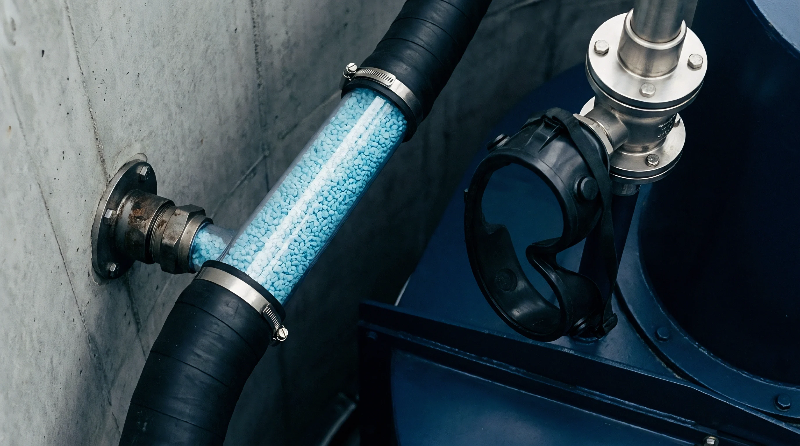
Transient thermal cooling distributions govern post-molding shrinkage and long-term part stability. Thermal gradients across the part wall generate asymmetric residual stress distributions. The internal stress state resolves into bending moments, manifesting as out-of-plane warpage once mechanical clamp restraint ceases.
Residual Stress Evolution
Polymer cooling follows a path dictated by the local pressure-volume-temperature (PvT) equation of state. Rapid surface chilling locks in an oriented, high-density skin layer under compressive stress. The insulated core cools slowly under decayed cavity pressure, experiencing severe volumetric contraction that pulls against the rigid exterior skin, driving the center-plane into tension.
Symmetrical cooling across both cavity halves keeps the residual stress distribution balanced across the neutral axis. Asymmetric cooling, common when core pins run hotter than cavity plates, shifts the neutral axis. The side that cools slower undergoes greater volumetric shrinkage, pulling the part toward the hotter tool surface.
Modifying pack profiles or increasing clamp time cannot correct warpage caused by unequal mold surface temperatures.
A supplier facing warpage out of tolerance typically increases holding time or drops overall chiller temperatures. Lowering chiller temperatures without equalizing core and cavity thermal flux accelerates part distortion by steepening the thermal gradient between opposite surfaces. The correct remedy requires adjusting coolant flow balance across individual circuit loops to equalize mold face temperatures within three degrees Celsius.
Unresolved thermal gradients across structural ribs leave persistent internal stresses, predisposing parts to premature environmental stress cracking under chemical exposure in service.


Dossier
Securing stable tool performance requires embedding thermal engineering requirements directly into purchase specifications and tooling design reviews. Tool buyers who omit cooling specifications from request-for-quotation packages surrender control over operational cycle times. The tooling contract must dictate cooling channel architecture, flow velocity thresholds, pressure drop limits, and maximum permissible steel temperature variance across the molding area.

Essential Sourcing Verification Items
A formal tooling qualification dossier includes simulation data validated against physical pressure drops and thermal measurements taken during early tool trials (T1). Sourcing teams enforce stability by requiring the tool builder to deliver verifiable calculations before releasing steel-cutting deposits.
The technical dossier incorporates five core thermal verifications:
- Transient thermal simulation reports showing surface temperature distributions across cavity and core plates, bounded by a maximum allowable surface variance of five degrees Celsius.
- Circuit hydraulic schematics documenting calculated Reynolds numbers above four thousand for every independent cooling channel, matching available factory pump pressures.
- Mold material certification confirming thermal conductivity values of specialized core inserts, sub-inserts, and baffle components under ASTM E1461 laser flash testing standards.
- Equilibrium thermocouple logs recorded across forty consecutive continuous cycles during pre-shipment runs, proving mold steel reaches thermal stability.
Contracts must state that production mold sign-off requires proving calculated cycle times using factory water temperatures rather than artificially refrigerated toolroom chillers.