Predictive Multiphysics Modeling of Cavity Wall Heat Flux Disparity in High Cavitation Tooling
Predictive multiphysics modeling of cavity wall heat flux balances thermal extraction across high-cavitation tooling to cut cycle times and eliminate warpage.


Flux
During the transient injection phase of high-cavitation tooling, heat transfers across steep thermal gradients. In medical and packaging molds running 64 to 128 cavities, thermal management operates far from steady-state conditions. Thermal energy passing through cavity walls fluctuates across the molding cycle, surging during injection and packing before decaying as the polymer solidifies.
Traditional steady-state calculations only yield cycle-averaged temperatures across tool steel, missing the localized thermal spikes that occur in the first 0.3 seconds of melt contact.
When high-velocity polymer melt enters thin-wall cavities under injection pressures above 150 MPa, viscous dissipation and wall friction create severe thermal boundary layers. Instantaneous local heat flux values routinely exceed 1.5 MW/m², causing tool steel surfaces to jump 20°C to 40°C above nominal coolant temperatures within milliseconds of melt arrival. This cyclic thermal pulsing introduces micro-scale stresses within cavity inserts, driving premature thermal fatigue and surface crazing.
Cavity wall heat dissipation varies nonlinearly with local melt contact pressure before interfacial air gap formation occurs.
Thermal contact resistance across the polymer-steel boundary changes continuously through the packing and cooling phases. Polymer thermal conductivity is extremely low ~ typically 0.15 W/m K to 0.35 W/m K ~ compared to tool steel conductivities of 15 W/m K to 45 W/m K. During high-pressure packing, intimate contact between molten resin and polished steel produces an interfacial heat transfer coefficient exceeding 2,000 W/m²K. As the polymer cools and undergoes volumetric shrinkage, the part shell detaches from cavity surfaces, creating a micro-scale air gap that drops the interfacial heat transfer coefficient below 200 W/m²K.
Determining the precise holding pressure needed to suppress micro-gap formation across thin-wall ribs without inducing core shift requires empirical calibration for varied resin melt indices.
Symmetry
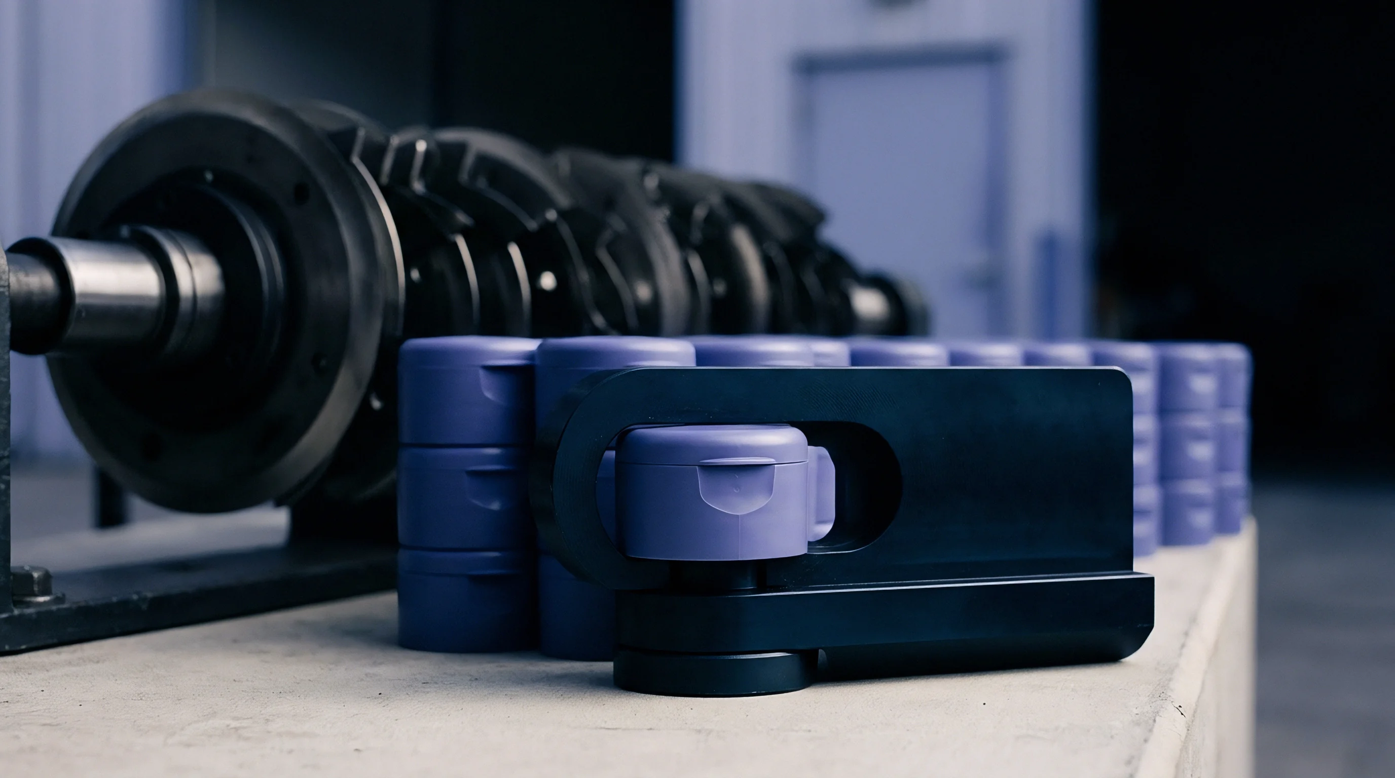
Multi-cavity mold layouts show inherent spatial variation in heat extraction despite identical cavity dimensions on engineering prints. Rheological and thermal non-uniformities arise directly from complex manifold geometries and shear-history distribution. As molten polymer traverses secondary and tertiary runner branches, non-Newtonian shear thinning concentrates high-velocity, hotter material near channel walls.
The melt entering central cavity clusters carries a higher thermal energy profile than resin arriving at outer perimeter drops, creating uneven heat distribution across the main tool block.
| Layout Zone | Melt Delivery Temp (°C) | Coolant Flow Regime | Peak Heat Flux (MW/m²) | Cycle-Averaged Wall Temp (°C) |
|---|---|---|---|---|
| Inner Cavity Cluster (Drops 25-40) | 238 | Turbulent (Re = 10,200) | 1.62 | 48.5 |
| Middle Matrix Rows (Drops 9-24, 41-56) | 234 | Turbulent (Re = 8,100) | 1.48 | 44.2 |
| Outer Perimeter Drops (Drops 1-8, 57-64) | 231 | Transitional (Re = 3,800) | 1.25 | 41.0 |
Coolant fluid distribution compounds thermal non-uniformity across high-density tool plates. Water flow remains turbulent only when local Reynolds numbers exceed 4,000 within every cooling channel. In complex 128-cavity plates, long fluid loops experience cumulative temperature increases along the circuit length, while total pressure drops degrade local flow rates in outer sub-circuits.
Reduced coolant velocity elevates film thermal resistance, trapping thermal energy inside core inserts and widening cavity-to-cavity wall temperature spreads.
- Volumetric Shrinkage Variance causes dimensional drift exceeding 0.08 mm across outer and inner cavity groups, breaching tight tolerance band limits.
- Localized Part Warpage develops when asymmetrical thermal extraction forces uneven core contraction, twisting long axial features away from nominal positions.
- Cycle Time Inflation occurs because processing windows are extended to satisfy the slowest-cooling cavity group within the central tool block.
- Core Thermal Fatigue accelerates micro-cracking along steel inserts subject to repeated high thermal gradients without adequate heat evacuation paths.
Coolant loops connected in series accumulate heat along the fluid path, making parallel manifold branching essential for uniform surface heat extraction.


Coupling
Numerical simulation models link non-Newtonian polymer melt dynamics directly to transient solid heat conduction within tool inserts. Resolving wall heat flux disparities demands two-way conjugate heat transfer modeling where the fluid domain and solid metal domain exchange energy boundary conditions at every time step. Cross-WLF viscosity parameters combined with modified Tait equations of state predict localized pressure drop, shear heating, and density changes during injection.
Transient thermal solvers simultaneously update steel temperature fields based on instantaneous polymer contact pressure.

Can Dynamic Cooling Channels Mitigate Core Shift Thermal Imbalance?
Slender cavity core inserts experience substantial fluid pressure differentials during the fill phase, inducing bending stresses that deflect core steel off-center. This core deflection shifts internal geometry, thinning the polymer channel on one side while expanding it on the opposite wall. The thinner wall section cools at an accelerated rate, causing premature local gate freeze and asymmetrical volumetric shrinkage, while the thicker polymer wall retains thermal mass longer and pulls the core further out of alignment.
Core deflection alters wall thickness, redistributing local thermal mass and driving self-reinforcing heat flux disparities.
Accurate multiphysics models couple structural finite element solvers with transient thermal conduction routines to capture this feedback loop. Contact resistance parameters change dynamically based on calculated local structural deformations. Ignoring structural-thermal interaction overestimates heat removal rates on the constricted side of the core by up to 35 percent, producing inaccurate warp predictions in final part geometries.
Failure to account for pressure-dependent core deflection in multiphysics simulations produces mold designs that experience chronic core bending, premature guide pin wear, and rejected wall-thickness tolerances during tool trials.
Deviation
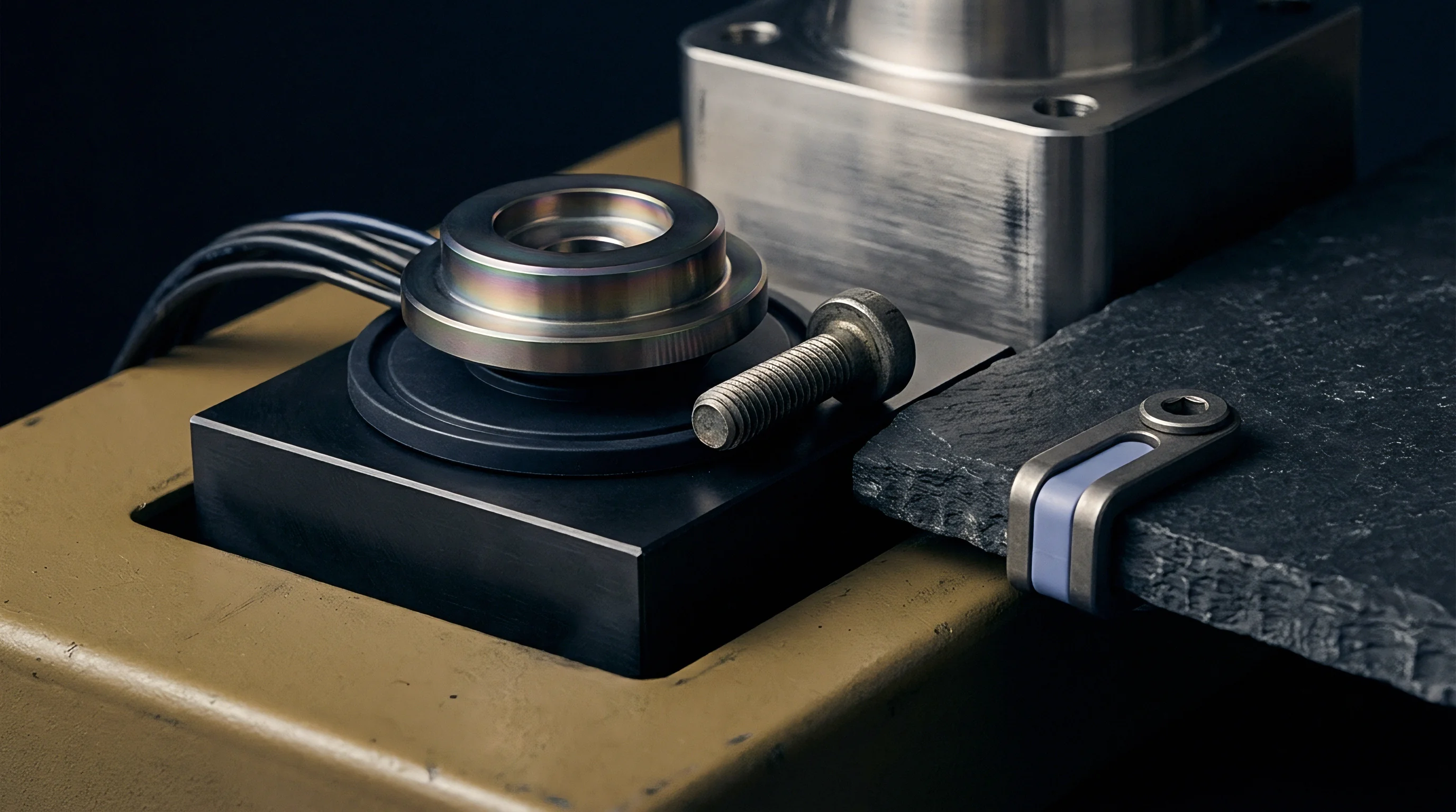
Experimental validation relies on embedded high-speed sensor arrays to capture real-time cavity surface temperature profiles. Fast-response coaxial thermocouples mounted flush with the mold surface register instantaneous thermal transients during production runs. Comparing press-side sensor telemetry against three-dimensional predictive solvers exposes discrepancies driven by idealized simulation boundary conditions, such as assuming constant coolant temperature or uniform mold plate contact.
| Metric Parameter | 3D CHT Model Prediction | Measured Press-Side Telemetry | Variance Range | Engineering Tolerance Limit |
|---|---|---|---|---|
| Peak Cavity Wall Temp (°C) | 52.4 | 56.1 | +3.7°C | ±2.0°C |
| Heat Flux Decay Time Constant (s) | 0.82 | 0.95 | +0.13 s | ±0.05 s |
| Core Surface Temp Delta (°C) | 14.2 | 18.8 | +4.6°C | ±3.0°C |
| Part Wall Thickness Spread (mm) | 0.018 | 0.027 | +0.009 mm | ±0.010 mm |
Calibrating predictive models requires aligning solver heat transfer coefficients with observed press-side thermal decay curves. Standard simulation setups often overestimate steel conductivity by neglecting interfacial thermal resistance between stacked cavity inserts and main mold plates. Unadjusted models overpredict heat evacuation rates, masking thermal hotspots that emerge during continuous automated production.
- Install flush-mounted fast-response thermocouples inside designated inner and outer cavities 0.5 mm from the molding surface.
- Connect signal conditioning hardware to record surface thermal response at sampling rates exceeding 100 Hertz during cycle execution.
- Run the injection press under scientific molding protocols until thermal equilibrium is established across fifty consecutive shots.
- Export cavity wall temperature decay curves and compare local cooling time constants against transient conjugate heat transfer predictions.
- Adjust polymer-to-steel thermal contact resistance parameters within the solver setup to match measured heat evacuation rates.
Factory chilled water supply fluctuations often overshadow tool design calculations during thermal variance analysis.

Audit
Sourcing contracts incorporate thermal uniformity parameters into tool sign-off specifications prior to final asset acceptance. High-cavitation tooling purchases carry substantial capital risk. Procuring 64-cavity or 128-cavity molds without rigorous thermal capability requirements exposes buyers to long-term scrap costs, cycle time bloat, and cavity-to-cavity dimension imbalance.
Verification protocols focus on statistical process capability metrics across every individual drop rather than averaging measurement data across whole shot samples.
Tooling sign-off agreements mandate cavity-to-cavity wall temperature variation remain within a three-degree Celsius band across all active drops at operating cycle time.
Quality assurance standards like DIN 16742 establish clear dimensional tolerance classes tied to mold thermal stability. Holding tight tolerance classes (TG3 or TG4) on small-scale medical housings requires uniform cavity wall heat extraction. When thermal flux imbalance across cavity blocks creates localized shrinkage variations, individual cavities fall outside capability limits even if press process controls remain perfectly repeatable.
- Thermocouple Verification Matrix confirms individual cavity surface temperatures stay within specified thermal limits across full mold shifts.
- Statistical Cavity Capability Mapping measures critical dimensions across all drops to verify process stability under production press dynamics.
- Coolant Flow Rate Validation certifies turbulent fluid regimes in every circuit loop using calibrated pressure differential flow meters.
- Short Shot Shear Balance Test identifies fill non-uniformity stemming from melt temperature variations across secondary runner trees.
Mold acceptance protocols governed by DIN 16742 Tolerance Group TG3 specify that non-uniform thermal cooling causing dimensional variance beyond grade limits grounds immediate tool rejection at the supplier site.

Equilibrium
Thermal management strategies balance advanced tooling fabrication costs against per-piece cycle time gains. High-conductive copper beryllium or Ampcoloy core inserts conduct heat five times faster than standard tool steel, mitigating thermal accumulation in narrow cavity features. Additive manufacturing via Direct Metal Laser Sintering (DMLS) enables conformal cooling channels that closely follow complex cavity contours, maintaining equidistant cooling passages from polymer surfaces.
Consider a 64-cavity polypropylene cap tool running 15 million units annually on an automated press line billed at $85 per hour. The baseline tool drawing uses conventional drilled cooling lines, experiencing a 16°C core temperature disparity between inner and outer cavities. This thermal imbalance forces a total cycle time of 5.8 seconds to hold dimensions on the hottest central cavities, generating a 2.4 percent scrap rate from axial ovality warpage.
Redesigning the tool using transient multiphysics modeling incorporates DMLS conformal cooling inserts and Ampcoloy core tips. This modified steel construction adds $45,000 to the upfront tool build price, but payback calculations demonstrate the financial return:
- Cycle Time Reduction drops the production loop from 5.8 seconds down to 4.3 seconds, saving 1.5 seconds per shot.
- Press Hour Efficiency reduces total operating time for the 15 million part run from 380 hours down to 281 hours, saving 99 press hours worth $8,415 per run.
- Annual Machine Savings across five production runs yields $42,075 in direct machine-hour expense elimination.
- Scrap Rate Suppression cuts scrap from 2.4 percent down to 0.2 percent, saving $14,200 in material costs per year.
- Total Financial Payback recoups the $45,000 tooling investment premium in less than ten operational months.
Conformal cooling circuits designed through transient thermal modeling reduce cycle time by 25 percent in high-cavitation closure molds.
Conformal channel cross-sections matched to local wall heat flux profiles maintain balanced extraction rates across complex mold inserts, stabilizing piece dimensions and securing continuous production margins.