Micro Injection Molding Alignment Systems and Tooling Tolerances
Sub-micron micro-molding requires center-line interlocks, powder-metallurgy steel, and rigid thermal control to eliminate parting line shift and flash.

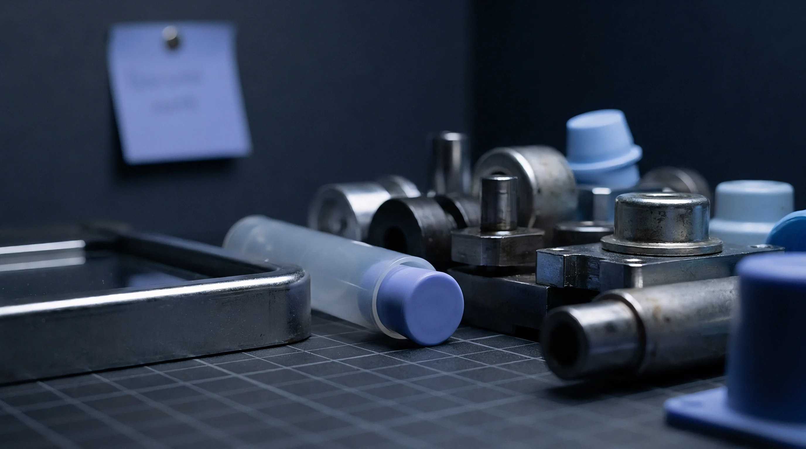
Pin
Micro injection molding drops part volumes below a single milligram and feature tolerances into sub-micron territory, where conventional mold base alignment hardware fails completely. Standard guide pillars built to ISO standards maintain radial clearances between 10 and 25 micrometers. That spatial play consumes the entire allowable tolerance band on components like optical fiber array ferrules, micro-fluidic pumps, and medical surgical grips.
When mold halves register with tens of micrometers of lateral float, the resulting parting line flash, core deflection, and wall thickness variance render micro-cavities unusable within a single production shift.
Achieving ultra-precision registration requires a tiered alignment hierarchy. Primary guides absorb initial mold engagement as it closes, secondary guidance aligns floating insert plates, and tertiary interlocks establish final zero-clearance registration before cavity entry. Eliminating lateral play requires mechanical interlocks operating on elastic deformation or taper contact optics.
Pyramidal interlocks and spherical taper registers replace cylindrical sliding surfaces, turning sliding clearance into controlled surface compression as the clamp locks down.
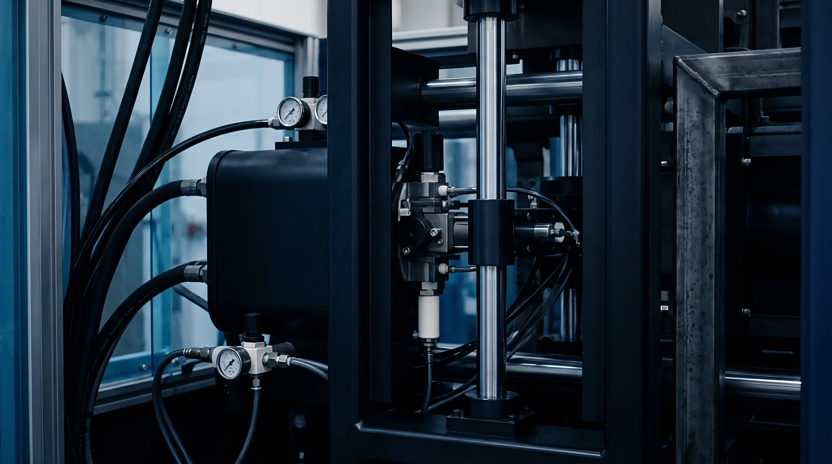
Primary Mechanical Registration Mechanics
Conventional sliding bushings rely on lubrication films that degrade micro-molded optics and bio-compatible polymers. Oil contamination in micro-cavities alters surface tension and causes immediate cosmetic and functional rejection. Roller-bearing guide pillars eliminate lubrication requirements while dropping radial play down to 1 to 3 micrometers.
Pre-loaded ball cages maintain continuous point contact between ground steel pillars and honed bushes, stopping stick-slip motion during micro-stroke closing sequences.
Centering accuracy across thermal cycles demands floating pillar mountings. Fixed guide pillars transmit thermal stresses directly into thin micro-cavity walls when mold halves experience temperature differentials. Sub-micron guide units utilize spring-preloaded bushings or flexure flex-pivots that absorb lateral expansion without transferring shear forces to delicate core pins.
The primary guide system brings mold plates within 5 micrometers of true center before secondary alignment features make physical contact.
Aligning mold halves at sub-micron precision requires mechanical interlocks that convert clamping force into lateral constraint without relying on fluid lubrication.
The choice between alignment mechanisms dictates both tooling cost and registration repeatability over hundred-thousand-shot production runs. The table below outlines performance metrics for primary and secondary micro-molding guidance systems under stable press conditions.
| Alignment Mechanism | Radial Clearance (µm) | Registration Repeatability (µm) | Thermal Mismatch Capability | Maintenance Interval (Shots) |
|---|---|---|---|---|
| Standard ISO Guide Pillars | 10.0 to 25.0 | ±12.0 | High lateral force transfer | 50,000 |
| Pre-loaded Ball Bushings | 0.5 to 2.0 | ±1.0 | Moderate point-contact wear | 200,000 |
| Four-Corner Tapered Interlocks | 0.0 (Taper seal) | ±0.5 | Low: requires paired expansion | 100,000 |
| Center-Line Pyramidal Inserts | 0.0 (Elastic contact) | ±0.2 | High: radial thermal freedom | 300,000 |
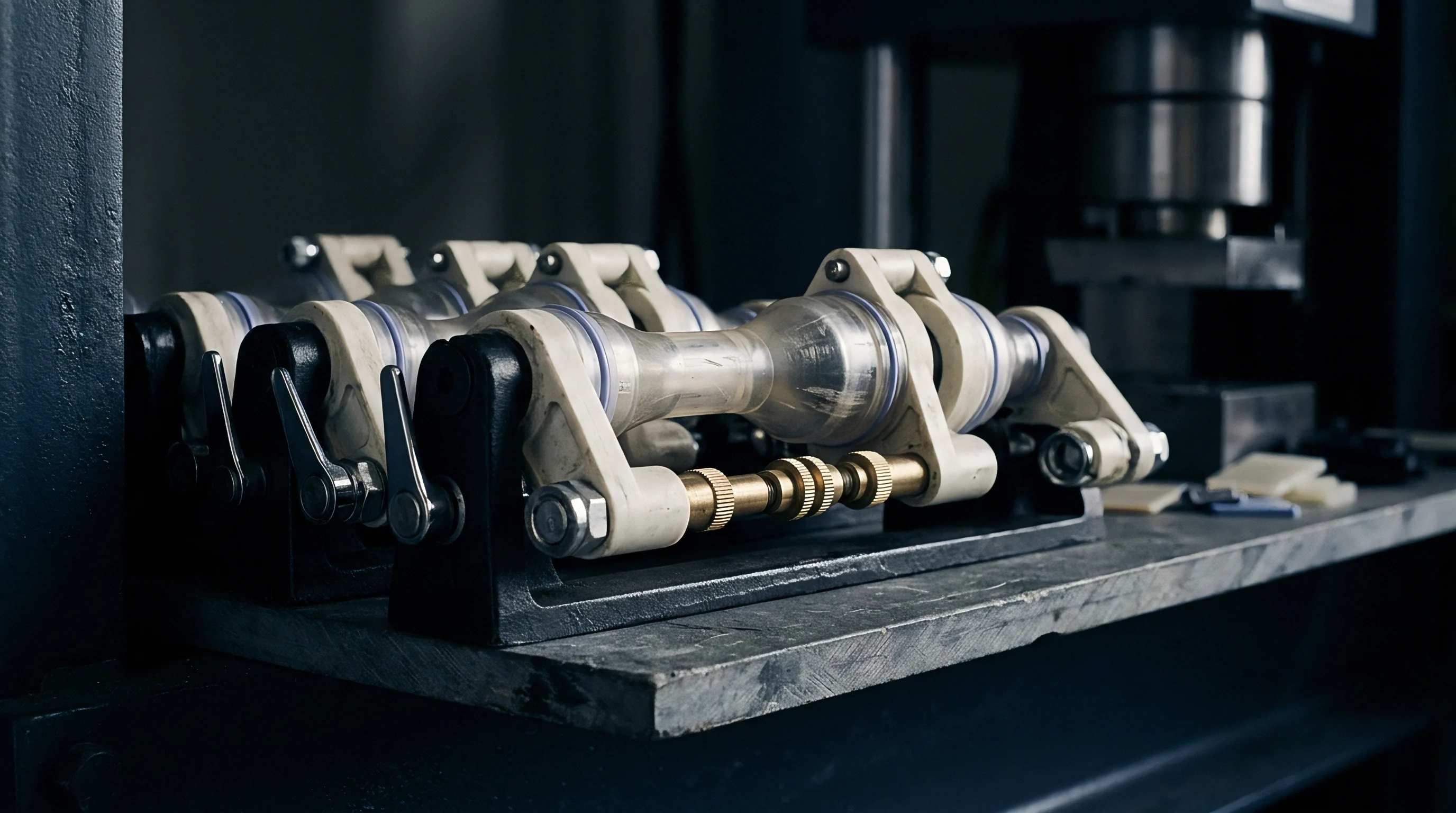
Interlock Geometry and Precision Alignment
Final registration occurs within the last 0.5 millimeters of mold stroke. Flat taper locks mounted on mold perimeters suffer from uneven thermal growth along machine diagonal vectors. Center-line pyramidal interlocks resolve this limitation by locating alignment features on the thermal neutral axes of the tool.
Four ground pyramid segments positioning into matching female pockets constrain all six degrees of freedom. Thermal expansion radiates outward along the pyramid flanks without altering the central coordinate datum.
Side-action cores and floating micro-inserts require dedicated local guide pins. Internal core alignment cannot rely on outer mold base positioning due to cumulative tolerance stack-ups across plate stacks. Pocket-milled micro-inserts carry individual micro-dowel pins ground to 0.001 millimeter diameter tolerances.
Setting these pins directly into micro-cavity blocks guarantees that core-to-cavity concentricity remains independent of mold base plate drift.
Selecting an alignment system requires verifying structural rigidity against asymmetric injection forces. Micro-injection speeds often exceed 800 millimeters per second, generating sharp hydraulic pressure spikes upon cavity fill. Improperly sized alignment registers deflect laterally, causing instant parting line wear and severe micro-burr formation.
- Center-line alignment geometry preserves pitch accuracy across changing mold temperatures by expanding along neutral thermal axes.
- Pre-loaded roller elements eliminate stick-slip motion during slow press close speeds without introducing liquid lubricants into cleanroom environments.
- Hardened tool steel inserts with diamond-like carbon coatings prevent adhesive galling on zero-clearance tapered interlock faces.
- Localized core guide pins decouple micro-cavity registration from mold base machining errors and platen alignment variations.
Failure to constrain lateral movement below 1 micrometer causes rapid edge rounding on micro-cavity parting lines, leading to uncontainable flash that ruins micro-features and mandates unscheduled tool rebuilds within fifty thousand cycles.

Heat
Thermal stability dominates micro-moulding precision far more than structural stiffness. Steel expands at approximately 11.5 micrometers per meter per degree Celsius. Across a modest 200 millimeter tool block, a temperature drift of merely 2 degrees Celsius shifts cavity dimensions by more than 2.3 micrometers.
In micro-injection molding, where part features often measure under 50 micrometers total width, thermal drift destroys dimensional repeatability across a shift.
Unbalanced temperature distribution between stationary and moving platens creates severe core-to-cavity misalignment. Hot runner manifolds, barrel radiant heat, and active water channels transfer unequal heat energy into opposing tool halves. The moving platen, subject to air convection during clamp opening, cools faster than the stationary side.
This differential thermal growth offsets upper and lower cavity halves, producing stepped parting lines and sheared ejector pins.
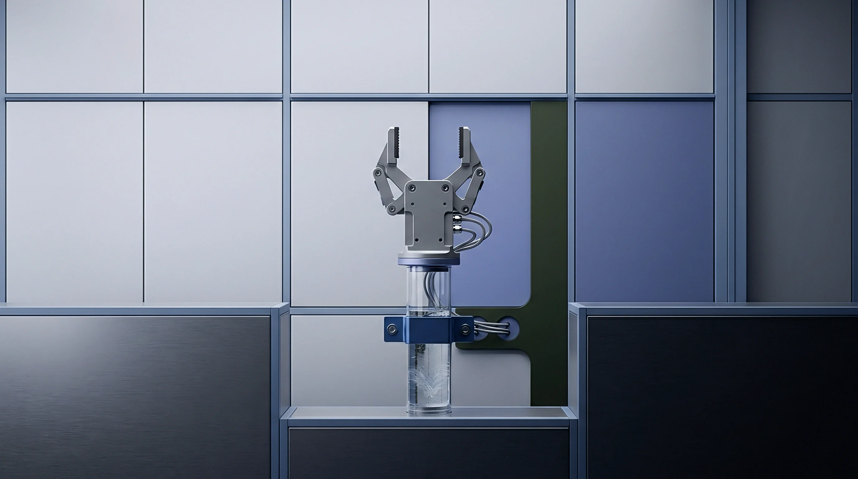
Differential Thermal Growth across Mold Plates
Managing heat paths requires structural insulation and dedicated cooling circuits inside every tool plate. Asbestos-free glass-reinforced polymer insulation sheets installed between mold base plates and machine platens reduce conductive losses. Uninsulated platens act as massive heat sinks, causing continuous temperature gradients across the mold base width.
Maintaining platen insulation thickness above 8 millimeters stabilizes internal plate temperatures within 0.3 degrees Celsius of target setpoints.
Thermal imaging during process bring-up reveals localized hot spots around micro-gates. High shear rates during rapid micro-injection elevate melt temperatures by 10 to 30 degrees Celsius at the gate entrance. Without localized cooling channels, heat builds up in small core pins that lack internal water passages.
Utilizing high-thermal-conductivity copper alloys, such as beryllium-copper or ampcoloy inserts, draws thermal energy away from uncooled micro-cores into main cooling lines.
A temperature differential of 3 degrees Celsius between mold halves shifts micro-cavity registration by over 2 micrometers, exceeding the total feature tolerance of micro-optical components.

Variotherm Temperature Control and Thermal Equilibrium
Micro-molding frequently employs variotherm technology to prevent premature melt hesitation in thin walls. Rapid induction heating or pressurized hot water cycles heat cavity surfaces above polymer glass transition temperatures during injection, followed by rapid chilling prior to ejection. Variotherm operations induce severe dynamic thermal cycles within cavity inserts.
Steel surfaces cycle through 80 degrees Celsius temperature swings within two-second windows, generating extreme localized thermal expansion stress.
Mitigating thermal fatigue demands powder-metallurgy stainless steels with fine, uniform carbide distributions. Tool steel selection must balance high thermal conductivity with resistance to cyclic thermal shock. Cooling channels manufactured via laser powder bed fusion enable conformal cooling loops that follow intricate micro-cavity contours.
Conformal cooling reduces thermal gradients across the cavity face to under 1 degree Celsius, preventing differential shrinkage and localized part distortion.
Equilibrium takes time to establish after press restarts. A micro-molding cell requires between thirty and ninety minutes of continuous automatic cycling before plate thermal growth stabilizes. Scrapping initial production units during thermal bring-up prevents non-conforming out-of-tolerance parts from entering cleanroom packaging lines.
Thermal stability relies on continuous fluid flow rather than static pressure in cooling circuits.
Stock
Raw steel selection establishes the absolute limit of achievable micro-cavity tolerance. Standard P20 or basic H13 tool steels contain carbide segregations, inclusions, and microscopic voids that disrupt sub-micron surface finishes. Micro-machining processes pull or fracture large carbide grains, leaving micro-pits on cavity walls that mirror onto molded polymer parts.
Powder-metallurgy steels, such as CPM 15V or ELMAX, and electro-slag remelted alloys like Stavax ESR supply ultra-clean steel matrices capable of mirror polishes below Ra 0.01 micrometers.
Fabricating micro-cavity features relies on advanced subtractive and additive machining methods. Wire Electrical Discharge Machining using micro-wires down to 20 micrometers in diameter cuts intricate slots with edge radii below 10 micrometers. Micro-sinker EDM requires high-density fine-grain graphite or tungsten-copper electrodes, operating at nanosecond spark durations to achieve sub-micron dimensional tolerances.
Diamond micro-milling utilizes single-crystal diamond tools running on air-bearing spindles at speeds up to 100,000 RPM to cut optical-quality micro-geometries directly into hardened steel stock.
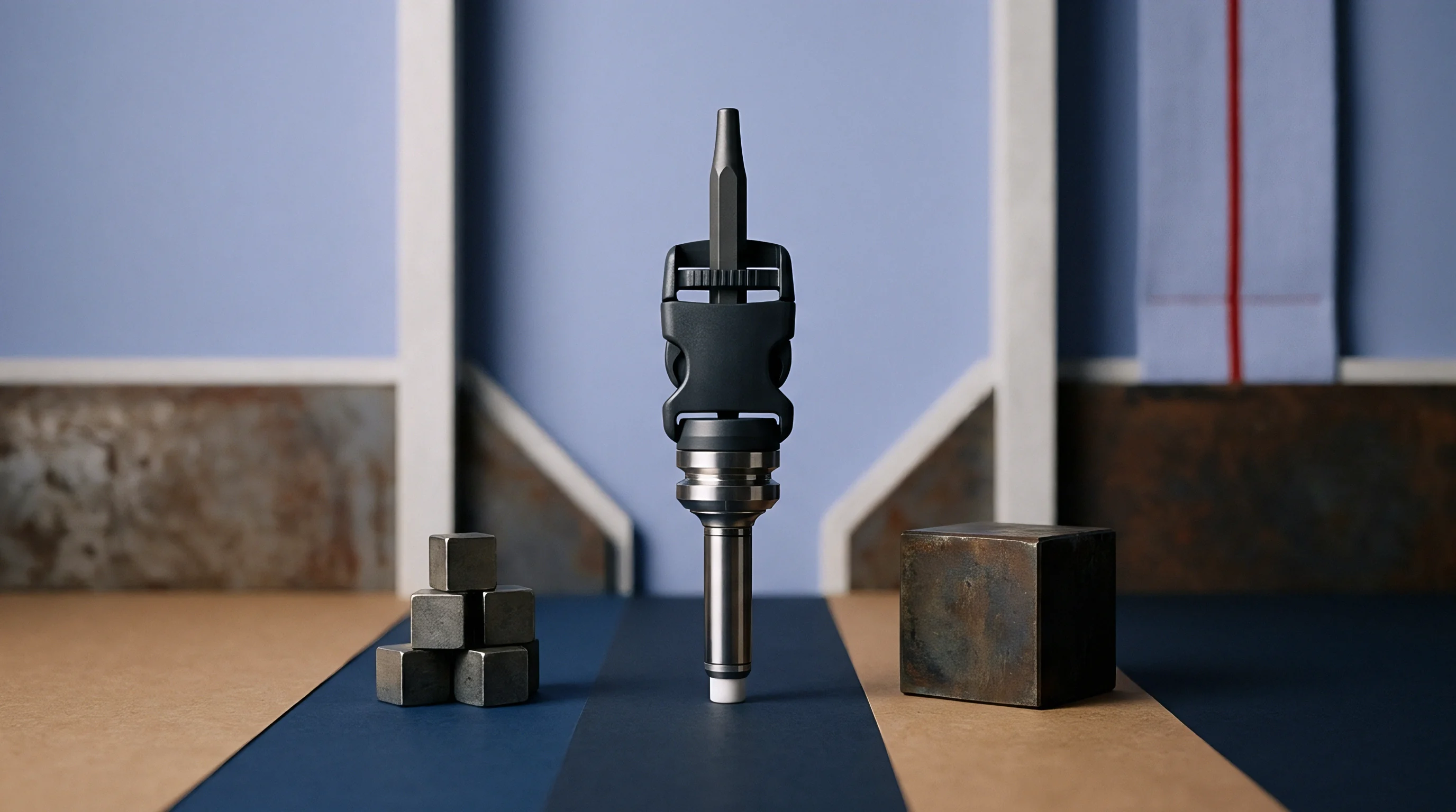
Substrate Metallurgy and Micro Surface Machining
Ultrafine-grain tungsten carbide substrates offer modulus of elasticity values double that of standard steel, reaching 600 GPa. High elastic modulus minimizes tool flexure under micro-milling cutting loads and resists cavity sidewall bulging under high injection pressure spikes. Carbide substrates cut with femtosecond laser ablation yield razor-sharp parting lines with zero burr formation, holding edge radii below 2 micrometers over long production runs.
Coating selection protects micro-machined surfaces against corrosive polymer off-gassing and abrasive glass-fiber reinforcement. Chromium nitride and physical vapor deposition diamond-like carbon coatings applied at sub-micron thicknesses protect cavity details without rounding off sharp micro-features. Coating deposition must maintain uniform thickness within ±0.2 micrometers across complex three-dimensional micro-cavities to prevent dimensional distortion.
Tool steel machining capabilities vary widely across precision fabrication methods. The table below lists process tolerances, achievable surface finishes, and minimum achievable feature sizes for micro-cavity manufacturing.
| Machining Process | Dimensional Tolerance (µm) | Surface Roughness Ra (µm) | Minimum Feature Size (µm) | Edge Radius Limit (µm) |
|---|---|---|---|---|
| Micro Wire EDM (0.02mm wire) | ±0.8 | 0.05 | 25.0 | 10.0 |
| Micro Sinker EDM (Nanosecond) | ±1.0 | 0.03 | 15.0 | 5.0 |
| High-Speed Micro-Milling | ±1.5 | 0.02 | 50.0 | 8.0 |
| Single-Crystal Diamond Turning | ±0.2 | 0.005 | 5.0 | 0.5 |
| Femtosecond Laser Ablation | ±0.5 | 0.08 | 10.0 | 2.0 |
| Data assumes climate-controlled machine enclosure held at 20.0 ± 0.1 degrees Celsius with direct-drive linear scale feedback positioning. | ||||

Cavity Stack Error Budget Allocation
Designing a multi-insert micro-mold requires rigorous arithmetic tolerance stack-up analysis. Calculating cumulative variation prevents interferences that cause plate bowing or excessive gaps that yield polymer flash. Combining pocket milling tolerances, micro-insert ground width variations, and dowel location errors using worst-case tolerance stack methods often yields total variations exceeding 10 micrometers.
Micro-moulding demands Root Sum Square statistical stack techniques coupled with selective assembly practices to hold assembly tolerances below 2 micrometers.
Calculating the tolerance budget for a micro-core insert stack follows a disciplined sequential method during tool design sign-off.
- Define the primary datum plane on the main mold base plate using precision optical flat measurements.
- Measure the actual ground pocket width of the insert receiver using high-accuracy contact probe metrology.
- Grind the micro-cavity insert block width to match the pocket dimension within a controlled clearance band of 0.001 to 0.002 millimeters.
- Calculate the center-line position variation of the micro-core feature relative to the insert block locating face.
- Determine the dowel hole location error on both the receiving pocket and the insert block using coordinate measuring machines.
- Sum the individual standard deviations of each component dimension to verify that total stack variance remains within the 0.003 millimeter process limit.
Micro-machining tolerances can reach under one micrometer on paper, but failing to account for ambient temperature swings during grinding renders those certificates invalid upon tool assembly.

Force
High specific injection pressure defines micro-injection processing. Small runner systems and sub-millimeter gates require injection pressures ranging from 1500 to over 2500 bar to push polymer melt into thin micro-cavities before frozen layer formation blocks flow. While total clamp force requirements appear small due to tiny projected part areas, high localized fluid pressures attempt to force parting lines open during peak packing phases.
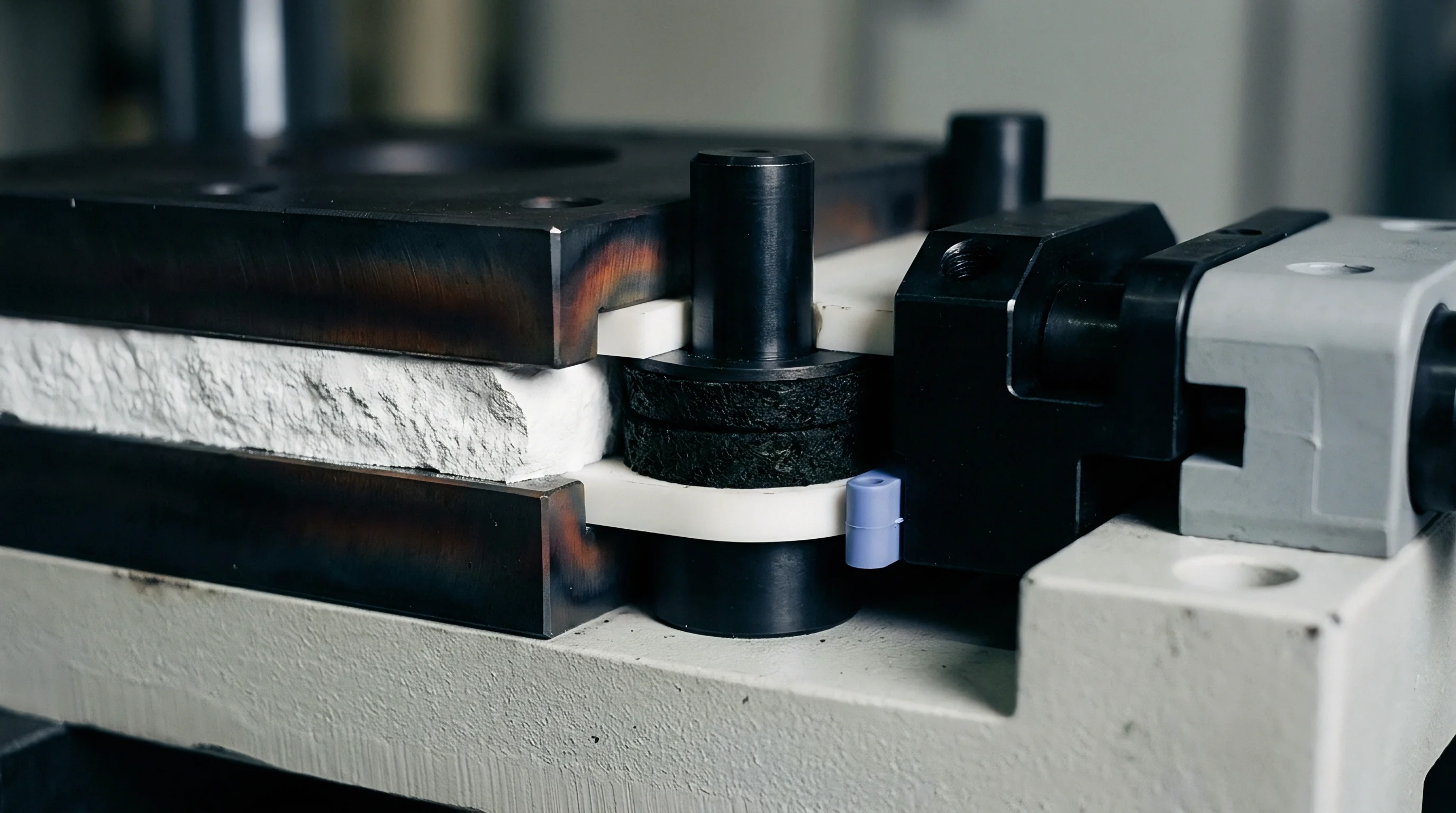
Platen deflection under clamping tonnage introduces significant alignment errors. Even high-precision electric micro-moulding presses exhibit minor platen bending when clamping force is applied. If tie-bar pre-tension varies by even two percent, the moving platen tilts out of parallel.
A platen tilt of 0.01 millimeters across a 300 millimeter platen face creates asymmetric compression on micro-interlocks, causing core offset and instant parting line flash on one side of the tool.
Does Electric Injection Hold Submicron Parting Precision?
All-electric micro-moulding machines utilize servo-motor driven ball screws or linear drives to control platen positioning and injection velocity. Servo-electric drives eliminate hydraulic oil thermal fluctuations, delivering positioning repeatability within 0.001 millimeters. High-speed piezoelectric load cells mounted behind tie-bar nuts monitor dynamic clamp force distribution in real time.
Dynamic clamp control adjusts tie-bar tension during injection to compensate for localized tool expansion, maintaining parallel parting line closure throughout high-pressure filling cycles.
Core pins inside micro-cavities face severe bending forces under asymmetric flow fronts. If molten polymer enters a micro-connector cavity faster on one side of a pin than the other, fluid pressure forces the core pin sideways. A core pin measuring 0.2 millimeters in diameter with an aspect ratio of 10 to 1 deflects several micrometers under a pressure differential of merely 50 bar.
Pin deflection alters local wall thickness, creates optical distortion, and causes core tip damage upon tool closing.
Parting line flash in micro-moulding occurs when dynamic fluid pressure inside the micro-cavity exceeds localized clamp pre-load, causing plate separation as small as 0.5 micrometers.
Asymmetric injection forces cause structural failure modes that compromise both part geometry and tooling longevity. The list below highlights critical structural risks encountered under peak micro-injection loads.
- Core pin shear bending occurs when non-uniform gate filling creates unbalanced fluid pressure across small pin cross-sections.
- Parting line separation blow-out manifests when peak packing pressure overcomes local mold plate pre-load, generating micro-flash across parting faces.
- Interlock galling results from forced alignment engagement under heavy platen tilting or unbalanced clamping force distribution.
- Ejector plate twisting causes misaligned pin advancement, leading to micro-ejector pin binding and localized cavity wall scoring.
Micro-tool designs must establish strict structural deformation limits, as dynamic clamp force adjustments cannot compensate for internal core pin bending.
Scan
Inspecting micro-molded components requires non-contact dimensional metrology systems. Conventional touch-trigger probes exert measuring forces between 0.05 and 0.1 Newtons. On a thin-walled micro-molded polymer component, that contact force deforms the part feature during measurement, introducing errors larger than the feature tolerance.
Touch probes can also scratch optical micro-lenses and damage delicate micro-fluidic sealing lips.
Non-contact 3D optical measurement technologies supply high-density point clouds without applying physical force. Focus variation microscopy, white-light interferometry, and confocal laser scanning microscopy capture sub-micron topographic surface maps. Focus variation measures steep sidewall angles up to 87 degrees on micro-gears, while white-light interferometry delivers vertical resolution below 0.1 nanometers for smooth micro-optical surface roughness verification.
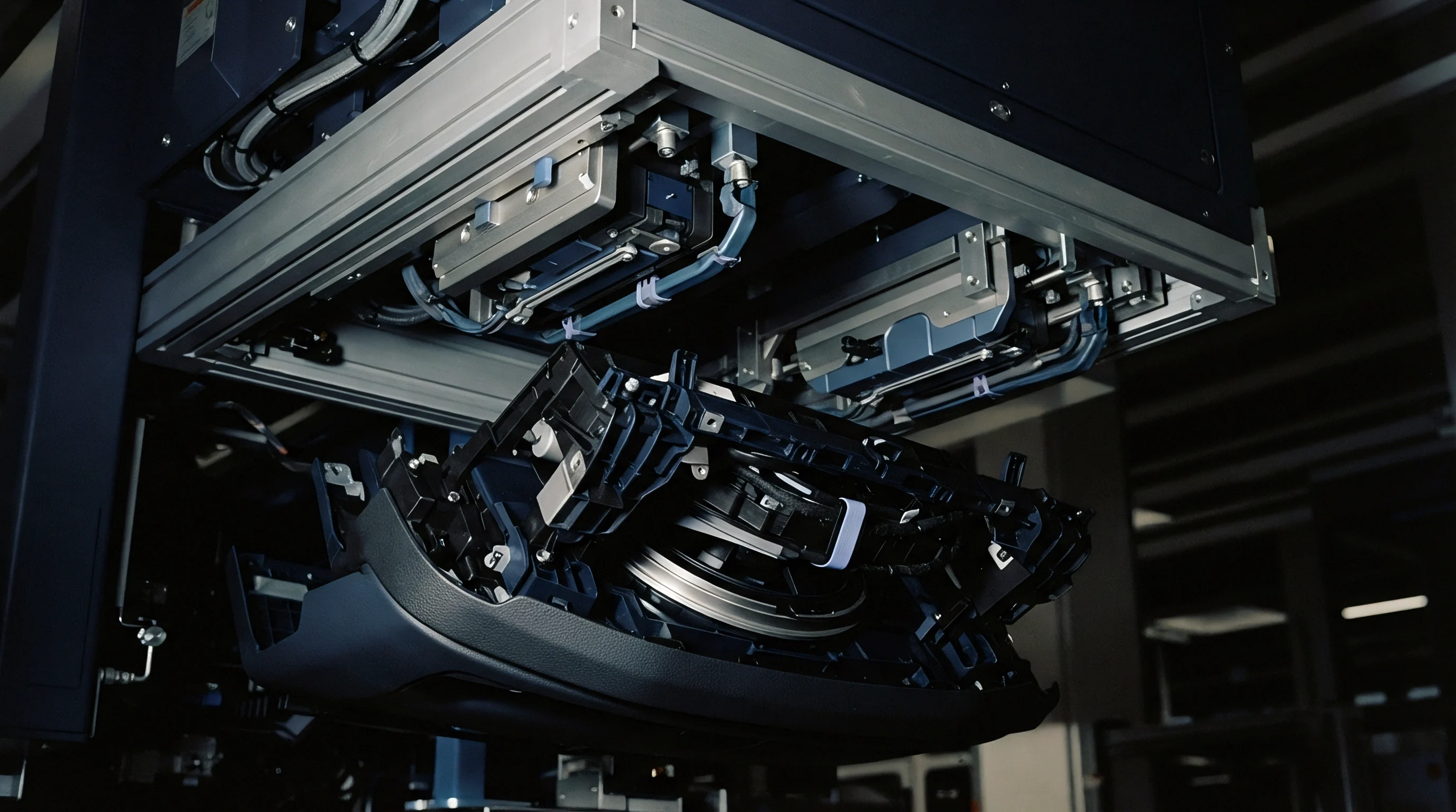
Non Contact Metrology for Submicron Geometries
Micro-computed tomography provides complete non-destructive internal feature inspection. High-resolution industrial micro-CT scanners utilize X-ray focal spots below 1 micrometer, generating full 3D volumetric datasets of micro-molded assemblies. CT scanning detects internal voiding, knit-line air entrapment, and core pin displacement inside opaque polymer housings without cutting or encapsulating samples in destructive cross-sectioning resins.
Environmental stability inside the metrology laboratory determines measurement validity. Dimensional inspection of sub-micron features requires climate-controlled rooms holding 20.0 ± 0.2 degrees Celsius and relative humidity under 40 percent. Measuring instrument tables must integrate active pneumatic vibration isolation to cancel floor vibrations caused by external press operations and foot traffic.
Selecting appropriate metrology instrumentation demands matching system resolution against part tolerance bands. The table below compares high-precision non-contact inspection methods used for micro-moulding verification.
| Inspection Technology | Lateral Resolution (µm) | Vertical Resolution (nm) | Maximum Measurement Speed | Primary Measurement Application |
|---|---|---|---|---|
| Focus Variation Microscopy | 0.4 | 10.0 | High (3D surface area) | Micro-gear profiles, steep walls |
| White-Light Interferometry | 0.5 | 0.1 | Medium (Fringes) | Optical lens surface finish, steps |
| Confocal Laser Scanning | 0.2 | 1.0 | Low (Point raster) | Micro-fluidic channel depth, roughness |
| Micro-Computed Tomography | 1.0 | 500.0 | Very Low (Volume scan) | Internal voids, core pin displacement |

Quality Class Verification under ISO Standardisation
Molded part tolerances must conform to international standards tailored for plastics processing. Standard DIN 16742 and its international successor ISO 20457 define achievable molding tolerances based on resin type, part dimensions, and process stability. Micro-moulding standardly aims for Tolerance Series NW4 or NW3, representing the tightest achievable manufacturing bands.
Achieving ISO 20457 grade NW3 demands tool manufacturing tolerances under 0.002 millimeters and mold temperature variation within ±0.5 degrees Celsius.
Quality documentation for micro-molded components requires rigorous statistical capability proof. Short-term machine capability studies must demonstrate Cpk values exceeding 1.67 over a continuous 500-shot trial run. Evaluating capability requires measuring every shot across multi-cavity tools to isolate cavity-to-cavity variance from press thermal drift.
Validating micro-molding tooling performance requires delivering a structured technical dossier prior to commercial tool sign-off and transfer.
- Optical surface topography profiles verifying cavity surface roughness Ra and root-mean-square slope values across functional optical areas.
- Non-contact coordinate measurement reports documenting full 3D nominal-to-actual CAD comparisons across critical feature dimensions.
- Multi-cavity capability statistical logs proving Cpk metrics above 1.67 for all critical micro-features across all active cavities.
- Computed tomography density maps certifying the absence of internal micro-voiding and structural porosity around high-stress micro-cores.
According to ISO 20457 clause 6.2, plastic part dimensional drawings must specify mandatory measuring conditions, including temperature, relative humidity, and conditioning duration, or the stated micro-tolerances are legally unenforceable during receiving inspection audits.
Margin
Tooling economics in micro-moulding differ dramatically from conventional injection molding practice. Steel machining and micro-alignment integration represent up to eighty percent of total tool build expenses, while raw material cost per part drops to fractions of a cent. A high-precision 16-cavity micro-connector tool equipped with sub-micron interlocks and conformal cooling inserts costs between 80,000 and 150,000 USD.
Protecting that capital expenditure requires precise maintenance budgeting based on production shot counts.
Consider a practical commercial worked calculation comparing baseline precision alignment versus sub-micron alignment systems over a 5,000,000-part production run. Assume a 16-cavity tool operating on a 3.5-second cycle time, producing PEEK medical micro-components weighing 0.005 grams each. The baseline tool utilizes standard guide pillars with ±5 micrometer repeatability, costing 60,000 USD.
The sub-micron tool utilizes center-line pyramidal interlocks and pre-loaded roller bushings, costing 95,000 USD.

Worked Example of Micro Cavity Amortization Mechanics
The baseline tool experiences minor parting line wear after 150,000 shots due to lateral micro-play. Wear generates a 10-micrometer flash buildup that exceeds the medical device print tolerance. Repairing the baseline tool requires complete cavity insert re-grinding and lock re-fitting every 200,000 shots, costing 8,000 USD per intervention and causing 24 hours of press downtime.
Over 312,500 total cycles required to produce 5,000,000 parts, the baseline tool requires 1.5 major refurbishments, adding 12,000 USD in maintenance and incurring 36 hours of press downtime priced at 150 USD per press-hour.
The sub-micron tool maintains alignment within 0.5 micrometers throughout 300,000 cycles before requiring minor refurbishing, costing 3,000 USD for interlock insert replacement. Yield analysis shows the baseline tool generates a 3.2 percent defect scrap rate due to flash and wall offset, costing 8,000 USD in lost PEEK resin and wasted press time. The sub-micron tool holds a scrap rate below 0.3 percent.
Amortizing the higher initial tooling capital expense across 5,000,000 good parts results in an overall lower unit manufacturing cost for the sub-micron system, proving that spending 35,000 USD more on alignment upfront saves money over the production lifespan.
Investing thirty-five percent more in pre-loaded center-line tool alignment reduces micro-molding scrapped yield by nearly three percent, fully recovering the initial capital outlay within the first million production parts.
Maintenance Triggers and Mold Asset Ownership
Preventative maintenance schedules for micro-molding assets operate on shot counters rather than calendar intervals. Cleaning micro-cavity air vents requires intervention every 20,000 to 50,000 shots. Polymer off-gassing clogs micro-vents measuring only 2 to 5 micrometers deep.
Clogged vents cause localized air diesel burns that destroy micro-cavity surfaces and mandate expensive EDM re-sinking.
Tool transfer contracts must explicitly assign legal liability for thermal bring-up damage and alignment interlock wear. A transferred micro-mold installed on an uncalibrated client press with non-parallel platens suffers severe interlock scoring within fifty cycles. Establishing baseline platen parallelism certification protocols protects the toolmaker’s warranty commitment and ensures long-term part conformance across vendor manufacturing sites.
Tooling sign-off documents require clear cavitation ownership clauses detailing spare insert provisioning. Procuring two complete sets of spare micro-cavity core and cavity inserts alongside the original tool build cuts unscheduled downtime from weeks to hours during unexpected pin breakage events.