Sub Micron Interlock Design and Precision Pocket Seating for Micro Molds
Sub-micron interlock alignment demands hard-milled pocket seating, preloaded kinematic tapers, and symmetric thermal control across core and cavity inserts.
Cavity
Kinematic Principles of Micro Registration
Sub-micron alignment between mating mold halves demands exceptional mechanical registration. Standard guide pins and bushings cannot maintain sub-micron repeatability because running clearances of two to five microns allow lateral movement during clamping. Precision micro molding instead relies on kinematic interlock assemblies located directly on insert pocket perimeters to eliminate relative movement prior to core entry.
Kinematic interlocks constrain five degrees of freedom through precision ground mating faces. Flat side locks transfer clamping forces directly into core and cavity inserts, preventing lateral deflection caused by asymmetrical melt front pressures. Symmetrical double-taper guides provide central registration, centering the insert array relative to the mold base structure.
Micro injection tool designs utilize pocket-mounted interlocks rather than plate-level locks to bypass thermal expansion differentials originating in external mold frames.
| Interlock Configuration | Alignment Precision | Radial Stiffness | Thermal Sensitivity |
|---|---|---|---|
| Flat Side Interlocks | 0.5 to 0.8 microns | High (120 kN/mm) | Low differential impact |
| Symmetrical Circular Taper Locks | 0.2 to 0.5 microns | Very High (180 kN/mm) | Symmetrical radial expansion |
| 4-Point Diamond/Spherical Seats | 0.1 to 0.3 microns | Medium (85 kN/mm) | Self-compensating center shift |
Micro-cavity positioning requires localized stiffness to resist high injection velocities. Polymer melt entering micro-channels at shear rates exceeding 50,000 reciprocal seconds creates unbalancing hydrodynamic lateral forces. If interlock stiffness falls below 100 kilonewtons per millimeter, core displacement exceeds sub-micron limits, yielding wall thickness variations across micro-features.
Interlock engagement depth exceeds three times the maximum core deflection under full injection pressure.
Underestimating the required interlock engagement depth leads to localized galling, tool steel plastic deformation, and immediate flash generation along micro-parting lines, destroying multi-cavity tool alignment within the first thousand molding cycles.

Datum
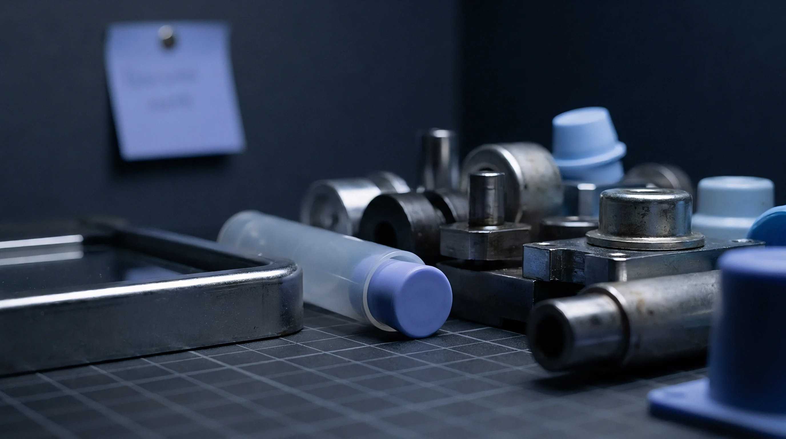
Micro Pocket Seating and Ground Datum Surfaces
Precision pocket geometry establishes the physical foundation for core and cavity inserts. High-speed CNC micro-milling achieves sub-micron pocket floor flatness when using oil-cooled spindles operating above 40,000 revolutions per minute. Floor surface roughness must stay below Ra 0.05 microns to prevent micro-asperity collapse under high clamping tonnages.
Pocket floor deflection alters parting line sealing integrity. Clamping pressure applied across an uneven pocket floor creates flexural stress within the core insert, lifting parting line edges by up to two microns. Flatness errors transmit directly through the insert assembly, causing uneven compression across micro-sealing dams.
Pocket sidewall orthogonality dictates insert stability under side-load pressures. Machining corner radii down to 0.2 millimeters requires micro end mills with tight runout tolerances. Standard milling processes leave minor fillet radii that interfere with insert ground chamfers, lifting the insert away from the true bottom plane.
- Fillet Radius Interference creates a gap under the insert floor, leading to flexural fatigue and cracking under 50-tonne clamp loads.
- Floor Asperity Collapse causes unpredictable datum settling across initial production runs, shifting Z-axis core positions by half a micron.
- Tapered Sidewall Draft reduces friction holding power, forcing the pocket to expand radially under high melt injection pressures.
- Corner Relief Defects concentrate mechanical stress at insert corners, causing micro-cracking in hardened powder metallurgy tool steels.
Precision grinding of insert datum faces using resin-bonded cubic boron nitride wheels creates parallel references within 0.3 microns across a 100-millimeter plate length. Lapping datum surfaces manually introduces edge rounding, which degrades sub-micron positioning accuracy along perimeter pocket boundaries.
Pocket sidewall relief angles below one degree increase galling risk during high-frequency clamp cycles.
Maintaining sub-micron parting line alignment over extended production cycles presents challenges due to natural press platen deflection and platen thermal expansion.
Wedge
Taper Preload Mechanics and Surface Hardening
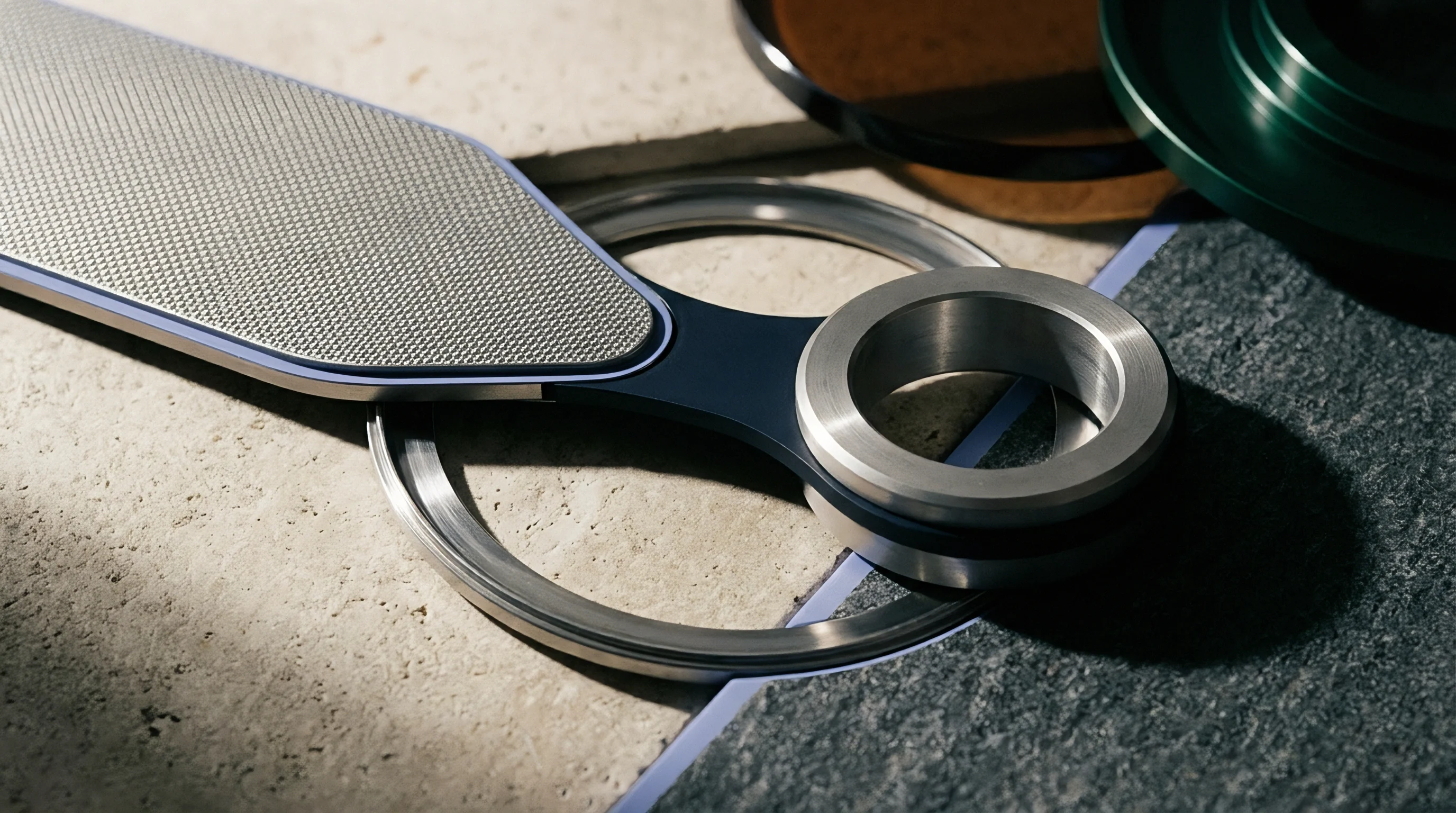
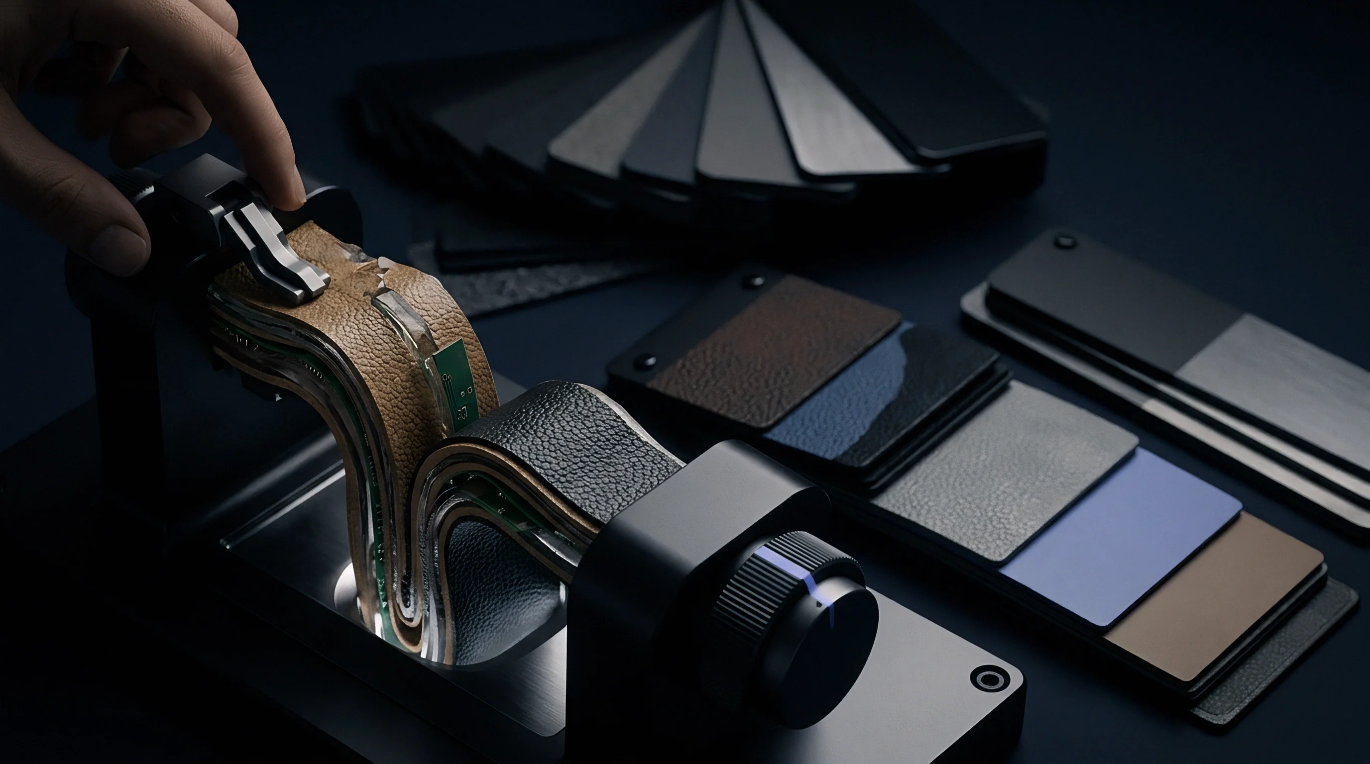
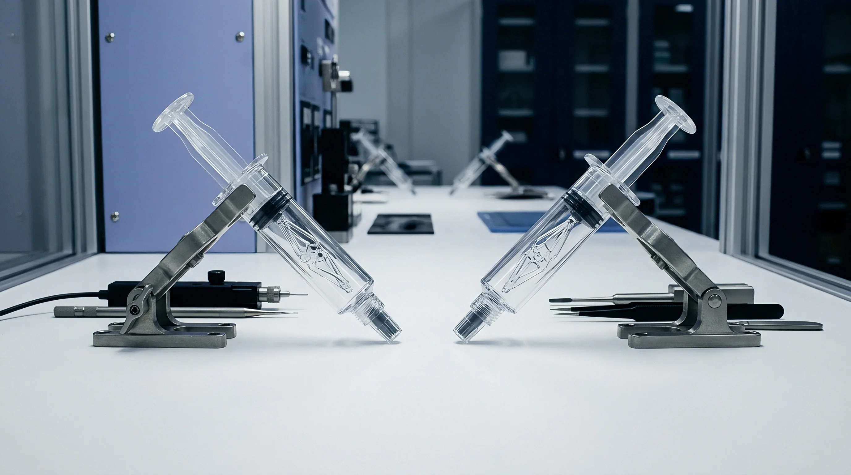
Preloaded taper interlocks provide zero-backlash positioning for high-cavitation micro tools. Taper angles ranging from one to three degrees generate mechanical leverage that forces mating surfaces into full face contact before mold halves seal, with preload setting final alignment.
Contact stress on interlock wedge faces frequently exceeds 300 megapascals during clamp closure. Sub-micron stability requires surface hardness values above 62 Rockwell C to resist mechanical wear and fretting corrosion over millions of cycles.
Taper Preload and Pocket Wall Spreading
Steep wedge angles generate severe outward radial forces against insert pocket walls. Conversely, when taper angles drop below one degree, increased mechanical advantage can force pocket sidewalls outward beyond their elastic yield point. That deflection leads to permanent pocket enlargement, destroying sub-micron insert seating precision.
- Clean interlock wedge faces with isopropyl alcohol to remove oil residues and debris particles prior to installation.
- Apply synthetic boundary lubricant containing sub-micron polytetrafluoroethylene particles sparingly onto sliding contact zones.
- Torque interlock mounting bolts in a cross-pattern to 70 percent of their yield strength using a calibrated digital torque wrench.
- Measure interlock preload engagement height using a digital dial indicator with 0.1-micron resolution.
- Verify complete face contact by applying blue layout fluid across taper faces and cycling the clamp under low pressure.
Selection of tool steel grade governs interlock surface durability. Powder metallurgy stainless steels like CPM S90V or Vanadis 4 Extra provide superior compressive strength and corrosion resistance compared to standard AISI H13 tool steel. Diamond-like carbon coatings applied at temperatures below 200 degrees Celsius increase surface hardness above 80 Rockwell C without altering heat-treatment dimensions.
Friction coefficients on sliding interlock faces must remain stable between 0.08 and 0.12 under continuous press operation to prevent wedge stick-slip during mold opening.

Drift
Thermal Mismatch and Active Cooling Controls
Temperature fluctuations across core and cavity plates introduce differential thermal expansion. Hardened tool steel expands at approximately 11.5 times ten to the power of negative six per degree Celsius. A temperature difference of two degrees Celsius across a 150-millimeter insert shifts hole-to-core concentricity by more than 3.4 microns, instantly exceeding sub-micron tolerance bands.
| Temperature Delta | Steel Expansion (1.2343 / H13) | Alignment Shift | Interlock Clearance Status |
|---|---|---|---|
| 0.2°C | 0.23 microns | Negligible | Optimal preload held |
| 0.5°C | 0.58 microns | Acceptable threshold | Boundary friction increases |
| 1.0°C | 1.15 microns | Sub-micron breach | Taper binding occurs |
| 2.0°C | 2.30 microns | Severe misalignment | Interlock galling imminent |
Conformal cooling channels built into pocket seating blocks stabilize local thermal gradients. Positioning oil or water circuits within three millimeters of interlock pocket seating faces removes heat generated by mechanical friction during high-speed clamping operations. Constant cooling fluid temperature control within 0.1 degrees Celsius maintains pocket dimensions during continuous shift operations.
A thermal gradient of 1.5 degrees Celsius across a 100 mm core plate shifts taper interlock alignment by 0.18 microns in hardened tool steel.
Unequal thermal mass between core and cavity sides causes transient offset during initial machine startup. Cavity plates heat up faster during hot runner thermal stabilization, shifting interlock seating centerlines relative to cold core plates until full thermal equilibrium is reached after several hundred molding shots.
Confirming sub-micron seating stability during dynamic high-frequency mold cycling requires active thermal monitoring across tool components.
Gauge
Metrology and Pocket Seating Inspection Protocols
Verifying micro-pocket geometry demands non-contact optical and tactile coordinate measuring instruments capable of 0.05-micron measurement uncertainty. White light interferometry measures floor flatness and surface micro-texture without touching sensitive ground datum faces. Micro-tactile probes using ruby stylus tips down to 100-micron diameters map pocket sidewall perpendicularity inside tight radii.
Environmental controls inside metrology rooms must hold ambient temperature at 20 degrees Celsius plus or minus 0.2 degrees Celsius. Measuring components exposed to shop floor temperature fluctuations yields invalid dimensions due to immediate thermal contraction or expansion.
- Coordinate Measuring Machine Uncertainty must not exceed ten percent of the specified feature tolerance band.
- Tactile Probe Force Limits must stay below 0.5 millinewtons to prevent surface scratching on lapped optical datum faces.
- Non-Contact Optical Scans require surface reflectivity calibration to eliminate false edge detection errors on ground steel.
- Thermal Soaking Requirements mandate that steel components rest inside the calibration room for 24 hours prior to measurement.
Dust particles measuring three to five microns present in standard factory air easily distort micro-pocket seating measurements. Assembly of sub-micron interlocks and inserts requires ISO Class 7 cleanroom conditions to prevent particle entrapment between floor seating planes.
DIN 16742 Class NW specifies tolerance limits for micro-molded features down to 2 microns without post-mold shrinkage correction.
ISO 2768-mH specifications governing general tolerances do not cover sub-micron positioning tolerances, requiring custom engineering drawings with explicit geometric product specification notes referencing ISO 1101 for form, orientation, and location controls.
Ledger
Tooling Amortization and Precision Cavitation Economics
Sub-micron pocket seating and custom interlock manufacturing increase initial tooling charges by 25 to 40 percent compared to standard precision mold bases. Precision wire electrical discharge machining and hard-milling processes demand high machine-hour rates on specialized toolroom equipment. Tooling investments yield lower piece costs by preventing flashing, reducing scrap rates, and extending mold maintenance intervals.
A multi-cavity micro tool costing 120,000 USD running at a 4-second cycle time produces 7.8 million parts annually across an eight-cavity configuration. Adding 30,000 USD for sub-micron kinematic interlocks and ground pocket seating increases total tool cost to 150,000 USD. If standard alignment systems yield a two percent scrap rate due to core shift flash, while sub-micron interlocks maintain scrap rates below 0.1 percent, the scrap savings equal 148,200 parts per year.
Assuming a resin and production cost of 0.25 USD per part, annual savings reach 37,050 USD, fully amortizing the precision interlock investment within ten months of continuous production.
| Machining Method | Achievable Flatness | Relative Tooling Cost | Maintenance Interval |
|---|---|---|---|
| Standard CNC Milling | 3.0 to 5.0 microns | 1.0x (Baseline) | 100,000 cycles |
| Precision Jig Grinding | 0.5 to 1.0 microns | 1.6x | 500,000 cycles |
| Ultra-Precision Hard Milling | 0.3 to 0.5 microns | 2.1x | 1,000,000 cycles |
| Femtosecond Laser Micro-Structuring | 0.1 to 0.3 microns | 3.2x | 2,000,000 cycles |
Amortization schedules rely on preventive maintenance protocols that clean and inspect interlock seating faces every 250,000 shots. Wear on replaceable interlock inserts can be monitored by tracking core shift trends on molded parts using automated vision inspection systems. Replacing worn wedge elements costs less than five percent of the initial tooling invoice, restoring original sub-micron registration without requiring complete tool base remanufacturing.