Calibrating Optical Coordinate Measurement Systems for High Gloss Thermoplastic Inspection
Calibrate deflectometry cells against black glass artifacts to eliminate matte spray errors and hold sub-five-micrometer precision on high gloss polymers.

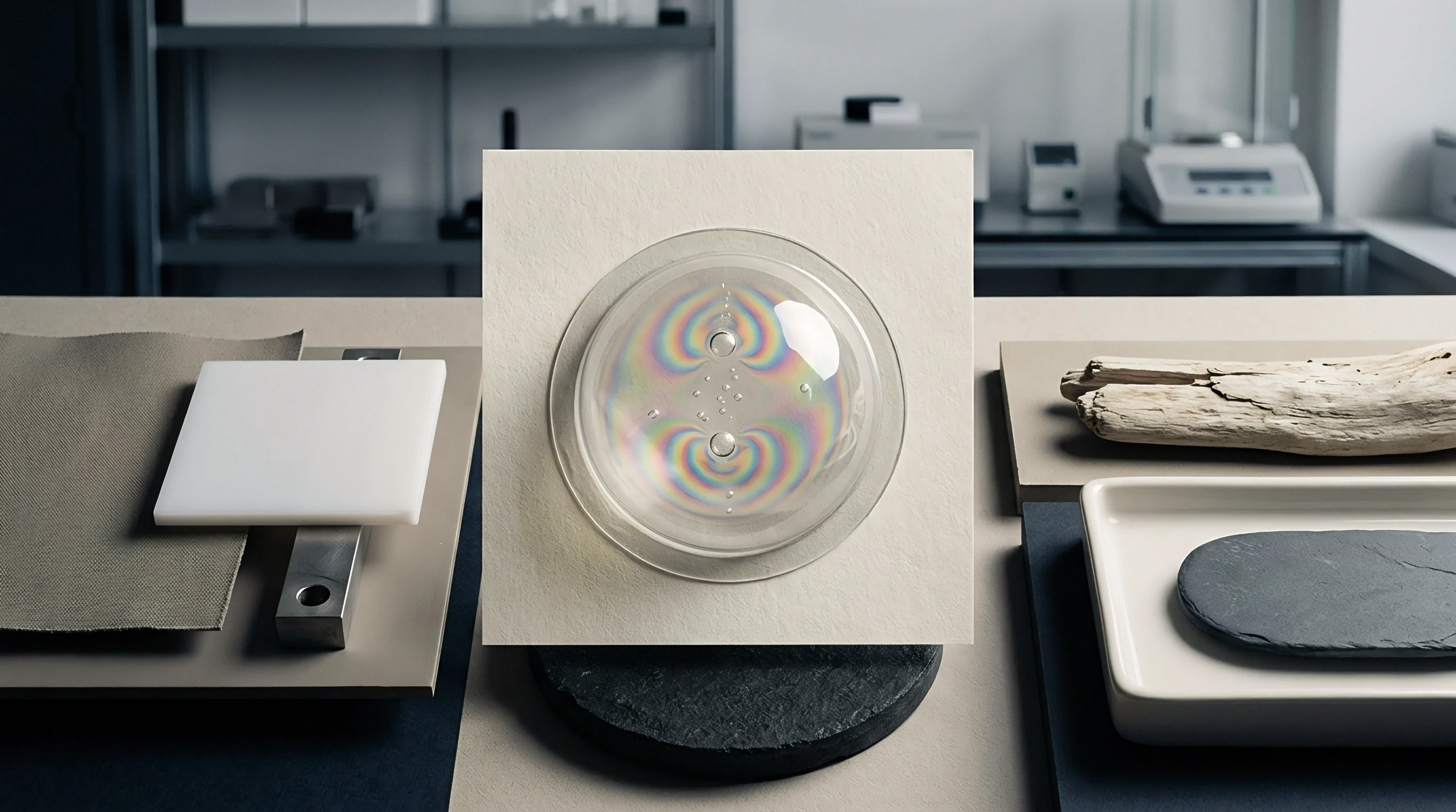
Glare
Specular reflection off piano-black polycarbonate-polybutylene terephthalate moulding strips blinds standard charge-coupled device cameras at twenty-four milliseconds of exposure. The reading fails. Conventional structured light scanners project sinusoidal fringes onto parts under the assumption of Lambertian scattering, where light diffuses uniformly across a hemisphere.
Class-A automotive exterior trim and optical consumer electronics present surfaces with gloss levels exceeding ninety-five gloss units at a sixty-degree observation angle under ASTM D523. Light striking these smooth polymer boundaries reflects directionally according to Fresnel equations, reflecting into the collection optics at blinding intensities or bouncing away entirely. The receiver registers either saturated pixel clusters or complete data dropouts across steep styling radii.
Toolrooms running high-cavity tools for high-gloss bezels face measurement discrepancies exceeding eighty micrometers between optical point clouds and tactile coordinate measuring machine benchmarks. Press setters frequently compensate by applying titanium dioxide or cyclododecane sublimating sprays to dull the show surface before digitisation. This practice destroys measurement integrity on tight clip locations and fine edge profiles.
A standard aerosol pass deposits between five and eighteen micrometers of uneven coating across functional rib roots and shut-off lands, directly consuming the production tolerance band defined by DIN 16742 TG4. Cyclododecane crystals sublimate unevenly over forty minutes at twenty-three degrees Celsius, introducing time-dependent datum shifts across a single scanning cycle.
A six-micrometer coating layer consumes twenty-four percent of the entire tolerance window on a DIN 16742 TG4 precision moulding.
Optical triangulation systems require diffuse returns. High gloss thermoplastics deliver direct specular bounce. Adjusting camera exposure down to prevent sensor saturation drops signal-to-noise ratios on dark substrates below five decibels, making surface reconstruction mathematically indeterminate.
When parts are inspected with mismatched optical setups, the resulting false rejections trigger unjustified tool steel modifications, permanently damaging cavity dimensions that were cut true to nominal CAD.
Fringe
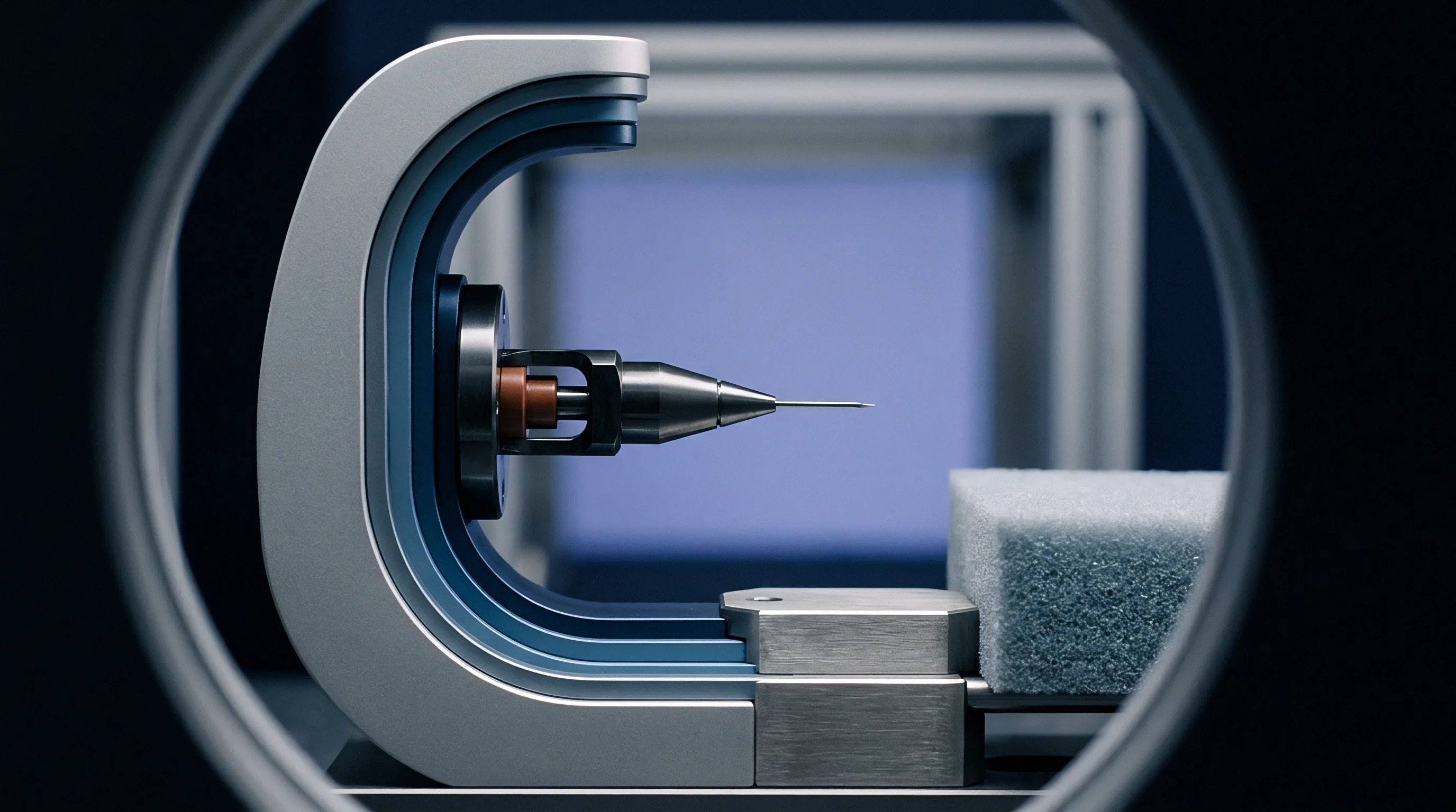
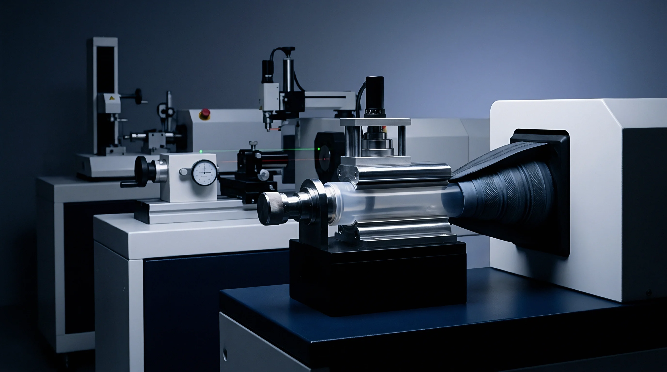
Phase measuring deflectometry records the distorted reflection of an active visual raster displayed on an illuminated screen rather than projecting patterns directly onto a diffuse body. The physical geometry involves an LCD or OLED monitor displaying known sinusoidal fringe patterns, the specular thermoplastic moulding acting as a mirror, and one or more calibrated area-scan cameras observing the reflected virtual image. Distortions in the captured fringe pattern correlate mathematically to local surface slopes, which integrate into three-dimensional coordinate topography.
Surface reflectivity exceeds ninety percent. This mechanism turns specular bounce from an optical defect into the measurement carrier itself, capturing local slope variations as small as one microradian.
What Governs Fringe Contrast on Specular Polymers?
Illumination wavelength and display luminance establish the modulation depth of reflected fringe sets. Injection-moulded black acrylic components absorb visible wavelengths while reflecting approximately four percent of incident light at the front interface via Fresnel reflection. Standard liquid crystal displays producing four hundred candelas per square meter deliver insufficient photon flux to high-speed complementary metal-oxide-semiconductor sensors through small optical apertures.
High-output light-emitting diode arrays yielding upwards of two thousand candelas per square meter overcome ambient shop-floor illumination, maintaining fringe contrast above forty percent across short integration times. Phase-shifting sequences typically deploy four, eight, or sixteen discrete phase increments per fringe period to cancel out non-linear sensor response and ambient light bias.
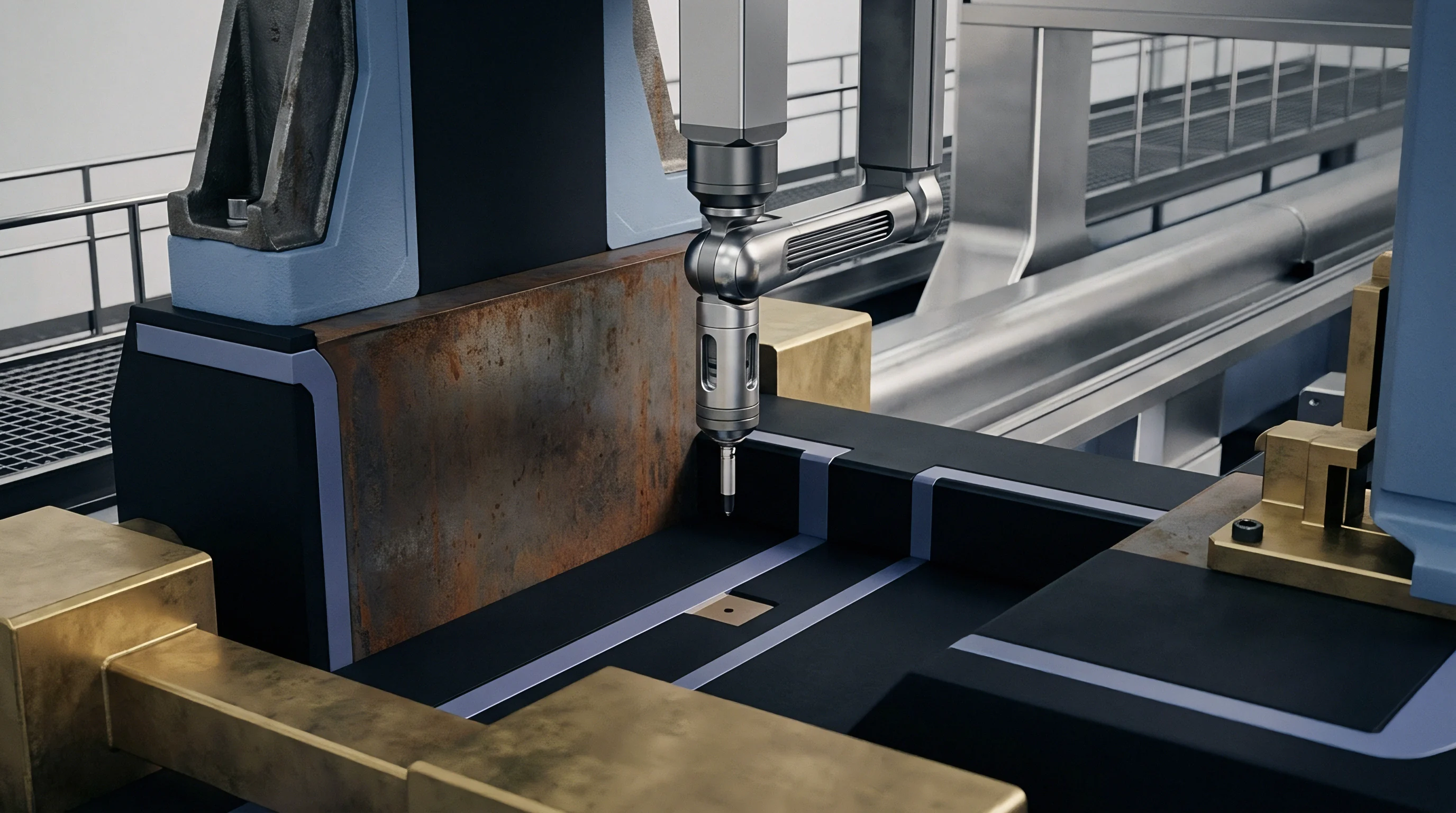
Geometrical calibration of the deflectometry cell establishes the spatial baseline connecting monitor pixels, polymer surface points, and camera sensor elements. Planar reference targets bearing arrays of chrome-on-glass dot patterns or ceramic retro-reflective targets cannot calibrate the system alone. Deflectometry contains an inherent slope-height ambiguity: an infinite combination of local surface heights and surface tilts produces identical ray deflections into a given camera pixel.
Resolving this ambiguity demands multi-view stereoscopic camera arrays, variable screen distances along the optical axis, or direct fusion with a sparse tactile probe dataset that pins the global spatial location of three primary locating features.
| Measurement Technology | Usable Gloss Range (GU) | Z-Height Uncertainty (μm) | Data Acquisition Time (s) | Surface Preparation |
|---|---|---|---|---|
| Structured Light Projection | 0 to 45 | 8.5 to 14.0 | 1.2 to 4.5 | Required above 50 GU |
| Point Laser Triangulation | 10 to 80 | 12.0 to 22.0 | 45.0 to 180.0 | Optional |
| Phase Measuring Deflectometry | 70 to 100+ | 1.5 to 3.5 | 0.8 to 2.5 | None permitted |
| Chromatic Confocal Array | 0 to 100+ | 0.4 to 1.2 | 60.0 to 240.0 | None permitted |
Stereo camera configurations fix rays in space by observing the same reflected screen point from two distinct visual angles. Optical triangulation requires diffuse returns, whereas deflectometric stereo solves point positions through ray intersection calculations. The spatial calibration procedure demands precise mapping of screen distortion, lens distortion through Brown-Conrady models, and relative camera-to-screen poses via coordinate transformation matrices.
Astronomical telescope fabricators polish parabolic mirrors using similar slope-integration mathematics; high-volume automotive moulding plants now deploy these identical optical principles across eight-second robotic inspection cells to verify class-A exterior panels.
Refraction through transparent or semi-translucent thermoplastics introduces secondary ghost reflections. Polycarbonate exterior light housings reflect light from both the front polished surface and the rear cavity surface. The back-wall reflection arrives delayed and refracted, overlaying a secondary phase-shifted fringe pattern onto the primary image.
Eliminating these secondary rays involves polarizing filters tuned to Brewster’s angle of the polymer (approximately fifty-six degrees for polymethyl methacrylate), narrow optical bandpass filtering, or ultra-short optical coherence gating. Failure to isolate the primary surface reflection leads to height errors equal to half the wall thickness of the part.
Calibration sequences for high gloss inspection cells require rigorous validation steps before signing off production capabilities.
- Target plate positioning establishes the global coordinate frame through a certified ceramic grid verified to VDI/VDE 2634 Part 2 standards.
- Camera extrinsic orientation maps the spatial vectors between visual sensors using bundle adjustment algorithms over thirty-six distinct orientations.
- Display monitor mapping corrects spatial non-planarity and pixel pitch variances across the active LED matrix using a calibrated pinhole photogrammetry rig.
- System bundle adjustment computes global projection transformations while locking residual reprojection errors below 0.08 pixels across the complete field of view.
- Specular artifact verification evaluates measurement repeatability against a traceable Zerodur optical flat exhibiting surface form deviations under twenty nanometers.
ISO 10360-8 Clause 6.3 assigns full measurement invalidity to any coordinate data set gathered where optical saturation or unresolved secondary reflections occur during sensor exposure.

Drift
Thermal stability inside the metrology cell governs measurement repeatability on engineering thermoplastics. An unfilled polycarbonate component has a coefficient of linear thermal expansion of sixty-five parts per million per Kelvin. A temperature swing of five degrees Celsius on a six-hundred-millimeter instrument panel bezel induces one hundred and ninety-five micrometers of thermal growth.
This expansion dwarfs the fifty-micrometer tolerance band allocated across critical mating tabs. Optical inspection fixtures fabricated from extruded aluminum profiles introduce another twenty-three parts per million per Kelvin of drift. The gauge loses trace.
Machine enclosures placed adjacent to injection moulding presses face extreme thermal stratification. Convective plumes from barrel heaters, open tool platens operating at eighty degrees Celsius, and cooling water circuits create localized air density gradients. These temperature variations bend optical light paths through variable atmospheric refraction.
Deflectometry systems depend on milliradian-level angular projections; convective turbulence introduces spatial noise that registers as artificial high-frequency waviness across flat surface profiles. Metrology housings must maintain internal temperature control within positive or negative 0.5 degrees Celsius, matching environmental conditions specified under ISO 1 for geometrical product specifications.
Calibration artifacts demand ceramic substrates. Standard metallic calibration spheres expand during shift handovers as ambient shop temperatures climb. Sintered silicon carbide or carbon-fiber-reinforced polymer reference bodies maintain physical dimensions within 0.2 micrometers per meter-Kelvin.
Validating high-gloss measurement systems requires calibrating the optics against mirrors rather than diffuse matte spheres. Polished black glass spheres with sphericity verified below 0.5 micrometers under ISO 12181 represent the sole defensible standard for high-gloss optical probing. Diffuse spheres introduce apparent phase shifts due to subsurface scattering within the calibration coating layer.
A shop-floor temperature gradient of three degrees Celsius displaces optical rays by six micrometers over a one-meter measurement path.
Polymer parts themselves drift continuously during the post-moulding window. Semicrystalline thermoplastics like polybutylene terephthalate experience secondary crystallization and volumetric shrinkage over forty-eight hours post-ejection. Amorphous resins like acrylonitrile butadiene styrene absorb ambient atmospheric moisture, expanding unpredictably along structural ribs.
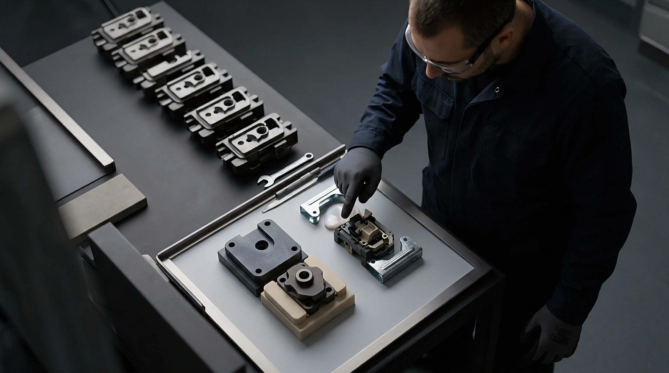
Calibrating the optical coordinate system solves only the machine side of the metrology loop. If parts enter the optical inspection cell without strictly verified cooling times, the gauge measures normal resin relaxation rather than tool geometry. The vendor claims the tool steel was machined incorrectly whenever parts measure out of specification.

Datum
Physical fixture points locate flexible thermoplastic parts into repeatable coordinate alignments without inducing mechanical strain. High gloss exterior trims possess thin nominal walls, commonly ranging from 1.8 to 2.5 millimeters. Clamping these components against rigid steel locators forces flexible flanges into artificial positions, concealing real moulding warpage.
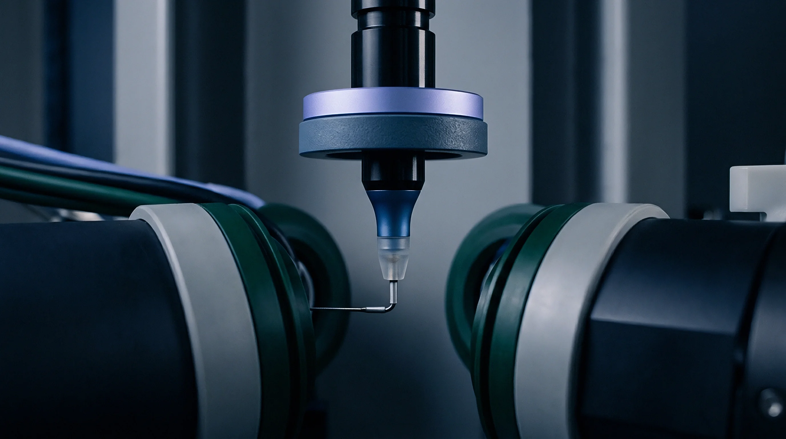
An over-constrained clamping nest shifts styling surfaces by hundreds of micrometers, generating corrupt point clouds. Metrology fixtures must follow exact 3-2-1 kinematic locating schemes using polished ceramic spherical pads, making contact only along functional reference points established on the original component drawing.
Which Reference Artifacts Establish Traceability for Shiny Contours?
Traceable calibration of optical freeform measurement loops requires calibrated freeform standards possessing known surface deviations. Step gauges, gauge blocks, and tooling balls verify linear axes and volumetric scale, yet they fail to test slope-measuring phase algorithms across dynamic curvatures. High-grade calibration standards utilize Zerodur or fused silica substrates diamond-turned to aspheric or sinusoidal wave topologies, finished with physical vapor deposition chrome or black optical coatings.
These reference plates provide calibrated slope gradients spanning zero to forty-five degrees with form uncertainty certified below fifty nanometers by national accreditation bodies.
| Uncertainty Contributor | Standard Value | Probability Distribution | Sensitivity Coefficient | Uncertainty Contribution (μm) |
|---|---|---|---|---|
| Monitor Pixel Position Error | ±12.0 μm | Rectangular | 0.12 | 0.83 |
| Camera Optical Distortion Model | ±0.05 pixel | Normal (k=2) | 14.5 μm/pixel | 0.36 |
| Thermal Drift of Calibration Rig | ±0.8 °C | Triangular | 1.2 μm/°C | 0.39 |
| Ray Slope-Integration Error | ±2.5 μrad | Normal (k=1) | 0.45 mm/mrad | 1.13 |
| Part-to-Fixture Kinematic Seating | ±3.0 μm | Rectangular | 1.00 | 1.73 |
| Combined Expanded Uncertainty (k=2) | 4.84 μm across a 400 mm diagonal measurement field | |||
Consider a practical inspection scenario. Assume a high-gloss polycarbonate piano-black automotive radiator surround measuring eight hundred millimeters in length. Tooling engineers specify a profile tolerance of 0.50 millimeters relative to datums A, B, and C. The combined optical measurement uncertainty calculated across the deflectometry volume reaches 0.048 millimeters under standard operation.
Metrology standards demand an uncertainty-to-tolerance ratio below one to four, often targeting one to ten under ISO 14253-1 decision rules. The deflectometry setup leaves 0.404 millimeters of true process bandwidth for the injection press, absorbing less than ten percent of the total engineering tolerance. Laser triangulation scanners using powder sprays exhibit expanded uncertainties near 0.160 millimeters, consuming thirty-two percent of the permitted deviation before factoring in tool wear or resin shrinkage variation.
Alignment mathematics determine how optical point clouds register against reference CAD files. Raw point clouds fracture when software algorithms run best-fit surface alignments across non-critical aesthetic curves. Best-fit alignments distribute local sink marks, gate blush, and core deflections across the entire data body, masking out-of-spec dimensions at mechanical mounting points.
Coordinate system calibration must enforce constrained datum targets matching the mechanical assembly constraints: primary datum pads control planar orientation, secondary locators constrain translation, and tertiary pins halt rotational freedom.
Optical triangulation errors compound when scanning shiny polymers under steep draft angles. Critical features exhibit distinct scanning risks that require specific compensation techniques.
- Sharp edge radii cause severe ray splitting, which yields phantom edge blooms and requires mathematical filtering of pixels within two ray-widths of boundaries.
- Deep rib roots suffer from physical light starvation due to high aspect ratios, demanding auxiliary targeted LED spot projectors calibrated to the central camera axis.
- Internal core sinks alter local curvature rates abruptly, driving slope integration algorithms into local divergence unless constrained by boundary conditions.
- Secondary gate shear marks produce localized optical anisotropy in transparent polymers, shifting polarization states and requiring unpolarized illumination bands.
A compliant fixture that flexes the moulding during datum seating guarantees an invalid inspection report regardless of optical accuracy.

Audit
Tooling sign-offs depend entirely on dimensional capability studies backed by traceable metrology systems. Buying injection moulds from overseas toolmakers carries severe financial exposure when initial tooling trials show discrepancies between the vendor’s optical inspection dossier and the receiving plant’s tactile CMM checks. Injection moulds run hundreds of thousands of dollars; a single four-cavity hot-runner tool for an exterior gloss moulding commands between eighty thousand and two hundred and twenty thousand dollars in toolroom steel commitment.
Misidentifying sink marks as gross tool shrinkage errors leads toolmakers to weld or electro-discharge machine cavity steel, permanently ruining parting lines and surface finishes.
Production release contracts must stipulate metrology validation protocols before cutting P20, H13, or mirror-grade Stavax ESR stainless steels. Acceptance criteria under factory acceptance tests require gauge repeatability and reproducibility (GR&R) scores below ten percent on all critical-to-quality dimensions across thirty consecutive shots pulled during steady-state cycling. If a vendor supplies scan data gathered via unstructured manual scanning or systems relying on temporary aerosol coatings, the buyer holds full commercial authority to reject the initial sample inspection report.
The purchase order must identify the specific coordinate inspection system, the exact ambient operating temperature window, the certified reference standards used for system recalibration, and the fixture restraint methods.
Calibration logs must accompany tool trial submissions. The optical coordinate system must possess a calibration certificate dated within six months of the trial run, traceable to an accredited ISO/IEC 17025 laboratory. This certificate documents the volumetric length measurement error across the entire working envelope.
If the vendor cannot produce volumetric calibration records for their optical scanner, the parts must be shipped to a third-party metrology laboratory for verification at the moulder’s expense. The buyer pays twice when ambiguous inspection protocols obscure whether tooling steel or thermal press drift produced out-of-spec components.
Significant contention remains regarding whether true volumetric trace can ever be maintained on freeform plastic panels subject to rapid ambient humidity absorption, leaving unresolved the legal boundary between acceptable resin moisture expansion and genuine toolmaker steel errors.