Resolving Structural Deflection and Pressure Loss Decay in Ultra Thin Wall Multi Cavity Tooling
Dynamic deflection and pressure loss decay require rigid pre-loaded bolsters, tapered core interlocks, and rheologically balanced hot runner delivery.


Deflection
Plates bend under twenty-four hundred bar of cavity pressure, and thin walls freeze before the machine can compensate. In thin-wall packaging and medical disposables, where nominal wall thicknesses drop to 0.35 mm across flow lengths exceeding 90 mm, a flow-length-to-thickness ratio above 250:1 turns tool compliance into a primary processing variable. A toolmaker spots parting lines flat on a granite bench under zero load.
Clamping forces of five thousand kilonewtons combined with peak injection pressures deform the core inserts, bow the support plates, and compress the backing blocks. That mechanical compliance changes the cross-sectional geometry of the cavity while melt travels through it.
Core shift destroys wall thickness symmetry. A core pin cantilevered into a medical barrel or deep-draw container deflects sideways when the flow front reaches one side tenths of a millisecond ahead of the other. As the melt channel thins on the lagging side, flow resistance increases exponentially with the third power of the channel height.
The high-pressure side pushes the core further off center. This feedback loop produces zero-flow hesitation, flashing along the heavy side, and short shots on the starved wall. The tool layout dictates whether this deflection stays isolated or cascades across neighboring cavities.

Mechanical Load Distribution across Cavity Arrays
Multi-cavity arrangements multiply mechanical compliance challenges. Standard calculation protocols often assume rigid boundary conditions at the tool plates. A thirty-two-cavity tool running an in-mold labeled tub encounters total separating forces exceeding four hundred metric tons over an injection duration of two hundred milliseconds.
High-speed hydraulic and all-electric toggle presses transfer this load through the machine platens. Platens themselves exhibit spherical deflection profiles under maximum clamp load. The center cavities experience higher plate compression than peripheral positions, creating an uneven starting condition before injection begins.
DIN 16742 Group 4 tolerance enforcement requires dynamic cavity pressure containment within five percent across all parting surfaces.
Backing plate thickness governs the structural floor. Standard mold bases frequently use 1.2312 or 1.2085 pre-hardened steels for support plates. These materials offer low yield strengths between 850 and 1000 MPa and elastic moduli near 205 GPa.
Under thin-wall injection spikes, standard plate stacks flex by 0.04 mm to 0.08 mm across the centerline. A dynamic displacement of 0.04 mm represents more than ten percent of a 0.35 mm nominal wall. This mechanical breathing relieves local melt pressure, drops the local shear rate, and accelerates premature wall freeze-off.
The resulting physical scrap arrives as short shots or severe flash depending on clamp tonnage settings. When an operator increases clamp force to eliminate flash caused by plate bowing, the parting surfaces at the tool perimeter crush, permanently sinking the outer land areas. Tooling lifetime drops from five million cycles to fewer than eight hundred thousand before parting line restoration becomes necessary.
Tool longevity directly depends on resolving these deflections during mechanical layout design rather than adjusting press parameters during production runs.

Decay
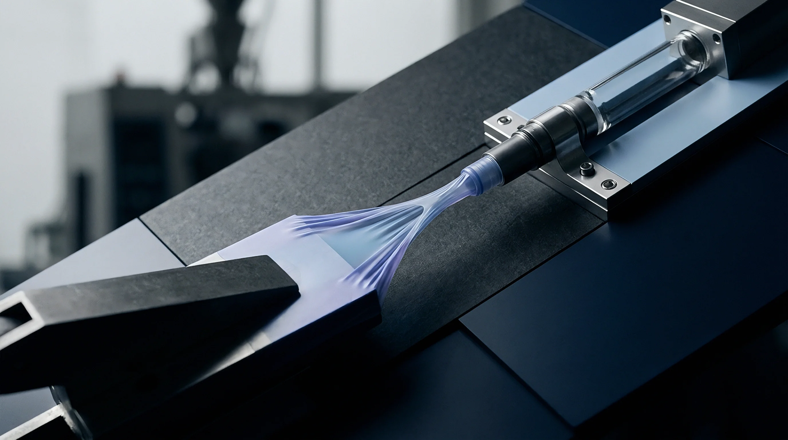
Viscous dissipation heats polymer melt while boundary layers freeze instantly against hardened steel walls. In ultra-thin sections, high injection velocities generating shear rates above 50,000 reciprocal seconds lower apparent viscosity. The flow mechanism remains governed by the Hagen-Poiseuille relationship modified for non-Newtonian behavior via the Cross-WLF equation.
Pressure loss per unit length climbs steeply as channel clearance narrows, because flow resistance scales inversely with the cube of cavity depth. The frozen layer grows continuously during the filling phase, progressively restricting the operational flow channel.

Shear Thinning Limits under Extreme Fill Rates
Polypropylene grades with melt flow rates between 60 and 100 g/10 min require injection times under 0.25 seconds to fill multi-cavity food containers. The shear rate inside the gate orifice frequently surpasses 100,000 reciprocal seconds. At these shear rates, the polymer chains align completely, reaching the second Newtonian plateau where shear thinning ceases to provide further viscosity reduction.
Thermal conduction to the cavity steel dominates the remaining flow progression.
Steel temperature governs frozen layer development. Cavity surfaces operating at 15 degrees Celsius form a rigid skin within twenty milliseconds of melt contact. When tool plates deflect and open the cavity gap dynamically, the local shear rate drops instantly.
The melt viscosity jumps upward, initiating a catastrophic pressure decay along the flow path. Cavities positioned furthest from the main sprue experience reduced line pressure, shorting the parts along the final fill perimeter.
| Resin Type | MFR (g/10 min) | Melt Temp (°C) | Shear Viscosity (Pa·s) | Pressure Decay (bar/mm) |
|---|---|---|---|---|
| PP Homopolymer | 70 | 240 | 12.4 | 18.5 |
| PP Random Copolymer | 45 | 235 | 18.1 | 26.2 |
| HDPE Injection Grade | 30 | 220 | 24.6 | 33.8 |
| PS High Impact | 18 | 210 | 31.2 | 41.5 |
| COC Medical Grade | 35 | 260 | 28.4 | 39.1 |
Cavity-to-cavity flow divergence increases with array size. Cold runner systems prove wholly unviable for thin-wall multi-cavity tools because pressure drops through cold branches consume machine capacity before melt reaches the gate. Valve-gated or hot-tip systems remain mandatory.
Hot runner manifolds experience thermal expansion differentials, creating internal pressure gradients if heater zones fluctuate by even two degrees Celsius. A localized viscosity shift alters volumetric flow rates into individual cavities, introducing filling imbalances across sixty-four-cavity tools.
Process setters frequently mask pressure decay by elevating machine injection speed. Doing so pushes peak hydraulic pressure against the maximum pump limit, inducing severe barrel pressure spikes and accelerated check-ring wear. Overcoming structural resistance with raw machine pressure accelerates platen and tool fatigue while failing to resolve flow-front starvation in mechanically compromised cavities.
The physical solution demands balancing flow geometry with rigid mechanical backing.
The standard procurement contract places financial responsibility for flow imbalance on the tooling fabricator whenever volumetric variation between cavities exceeds three percent at ninety-five percent fill volume.


Stiffness
Rigidity in thin-wall tooling requires specialized structural layouts and materials. Conventional tool construction relies on mild steel plates separated by tall ejector rails, creating an unsupported span directly beneath the central cavities. Under five thousand kilonewtons of clamp load, this open bridge functions like an unsupported beam, deflecting downward toward the ejector housing.
Eliminating this bending span requires replacing traditional ejector housings with solid structural pillars, integrated bolster plates, or perimeter stripper sleeves driven from the machine platen.

Core Interlocking and Support Pillar Architecture
Self-centering taper locks provide localized structural rigidity against core deflection. Standard flat parting lines allow lateral core movement up to the guide pin clearance, which commonly measures between 0.012 mm and 0.025 mm. Conical interlocks built directly into individual cavity inserts align cores precisely upon mold closure.
Taper angles ground between seven and ten degrees seat under pre-load, mechanically coupling the core insert to the cavity block. This configuration transfers lateral core forces into the compressive hoop strength of the cavity insert before melt injection begins.
- Direct Cavity Interlocking Rings prevent radial core migration during high-speed injection by capturing the core tip within an accurately ground hardened steel register.
- Pre-Loaded Center Bolsters counteract platen bending moments through hardened ground support pillars positioned within ten millimeters of cavity insert pockets.
- Through-Hardened Cavity Inserts utilizing 1.2344 or 1.2083 tool steels heat-treated to 54 Rockwell C resist localized compressive yielding beneath parting line shut-offs.
- Integrated Stripper Plates eliminate ejector pin holes, providing an unbroken steel surface that reinforces core base perimeters against cyclical fatigue loads.
Core steels demand extreme stiffness alongside impact resistance. High-wear tool steels with high young modulus values, such as powdered metallurgy grades or tungsten carbide inserts, limit elastic deformation. Standard tool steels provide a modulus of elasticity near 210 GPa.
Specialized powder metallurgy tooling alloys reach 240 to 260 GPa, cutting elastic displacement by nearly twenty percent under identical mechanical loads. Premium tooling solutions for extended production runs occasionally implement solid cemented tungsten carbide cores, offering an elastic modulus exceeding 550 GPa, which completely eradicates side deflection.
Elastic deflection of core cantilevers drops inversely with the fourth power of core diameter and directly with the material modulus.
Bolster support pillars require precision grinding. Unfinished or poorly fitted support pillars leave clearances of 0.03 mm to 0.05 mm, transferring loads through the plate stack until mechanical failure occurs. Pillars must be ground 0.02 mm to 0.03 mm proud of the ejector rails, forcing the entire clamp package into compression upon tie-bar stretch.
This pre-load configuration creates an ultra-stiff foundation, restricting dynamic tool opening during high-pressure injection to less than 0.008 mm across the parting plane.
Cavity pocket wall thickness requires identical discipline. Thin steel walls between adjacent cavities flex under differential pressure when one cavity fills ahead of its neighbor. Maintaining a minimum steel land of eighteen millimeters between cavity walls in a thirty-two-cavity array prevents insert deformation, preserving dimensional accuracy across high-speed packaging runs.
Tool builders often claim that standard guide pins and bushings provide sufficient core alignment during injection.


Manifold
Hot runner design determines whether pressure delivery matches the structural limits of the tool plates. A hot runner is not an open plumbing system. It acts as an active thermal reactor where melt residence time, shear degradation, and hydraulic pressure loss intersect.
In ultra-thin wall multi-cavity operations, pressure drop through the manifold frequently accounts for sixty percent of total injection capacity. The flow channels must balance pressure delivery against shear heating to protect resin properties.
Rheological Balancing in Multi-Drop Systems
Naturally balanced runner layouts enforce identical flow path lengths, channel diameters, and turn angles from the sprue bushing to every individual gate drop. Branched layouts utilizing eight, sixteen, thirty-two, or sixty-four drops divide flow symmetrically through successive binary junctions. Channel diameters step down at each split to preserve melt velocity and prevent stagnation zones.
A main channel diameter of twelve millimeters transitions to eight millimeters after the primary split, narrowing to five millimeters entering the nozzle drops.
| Flow Stage | Channel Diameter (mm) | Segment Length (mm) | Flow Velocity (m/s) | Stage Pressure Drop (bar) |
|---|---|---|---|---|
| Main Sprue Bushing | 14.0 | 120 | 0.85 | 45 |
| Primary Cross Branch | 10.0 | 180 | 0.83 | 82 |
| Secondary Branch | 7.0 | 140 | 0.85 | 115 |
| Tertiary Drop Feed | 5.0 | 90 | 0.83 | 160 |
| Nozzle Tip Orifice | 1.2 | 12 | 14.50 | 380 |
Thermal homogeneity along the manifold prevents viscosity variances among cavities. External band heaters and embedded tubular elements must provide uniform heating, controlled via multi-zone closed-loop systems. A thermal gradient of three degrees Celsius between the center drops and corner drops yields a twelve percent shift in polymer melt viscosity.
This viscosity differential disrupts fill balance across symmetrical runner layouts, leading to simultaneous flashing and short-filling defects.
Runner volume should not exceed three times total part shot volume to avoid thermal degradation during uninterrupted molding cycles.
Pressure losses escalate through nozzle tips. Hot-tip gate orifices for ultra-thin containers measure between 0.8 mm and 1.4 mm in diameter. At injection velocities exceeding eight hundred millimeters per second, the pressure gradient through this tip constriction can exceed four hundred bar.
Valve-gated systems using pneumatic or hydraulic actuation clear the gate orifice completely, eliminating tip freeze-off tendencies and reducing local pressure requirements by fifteen to twenty-five percent. Valve pin actuation requires mechanical synchronization across all drops to ensure simultaneous cavity entrance.
Manifold expansion dynamics dictate alignment with cold cavity inserts. Heated to 250 degrees Celsius, a four-drop manifold block expands several millimeters relative to the mold base held at 20 degrees Celsius. Hot runner nozzle tips must align perfectly with cavity gates at operational temperatures.
Machinists offset gate locations at cold conditions so thermal growth centers nozzles precisely over the cavity gates. Misalignment creates localized shear heating, asymmetric gate freeze, and rapid structural wear on nozzle tips.
Suppliers frequently recommend lowering nozzle temperatures when stringing or drooling occurs at the gate. Lowering temperatures increases local melt viscosity, elevates gate entrance pressure drops, and creates immediate short-shot patterns in thin-wall profiles. Stringing must instead be controlled through optimized gate cooling geometries and precise decompression stroke adjustments.


Cooling
Thermal management controls cycle times and stabilizes the structural geometry of the core insert. In thin-wall injection moulding, the cooling phase represents thirty to fifty percent of total cycle duration, frequently running under one second. Cooling must extract heat rapidly while maintaining uniform surface temperatures across core and cavity faces.
Uneven thermal shrinkage across thin-walled components generates internal stresses that trigger severe part warpage upon ejection.

Conformal Circuit Performance and Thermal Deflection
Conventional drilled cooling lines cannot follow the complex topographies of deep, thin-walled components. Drilled channels leave thermal stagnation points near the gate and container corners, causing thermal gradients along the part profile. Laser powder bed fusion additive manufacturing enables conformal cooling lines that track cavity contours at uniform distances.
Conformal lines positioned 2.0 mm to 3.5 mm from the moulding surface improve heat transfer efficiency compared to standard drilled water lines located fifteen millimeters away.
- Flow Velocity Optimization establishes Reynolds numbers exceeding 10,000 within all cooling channels, ensuring turbulent heat transfer across critical moulding surfaces.
- High-Conductivity Copper Alloys like beryllium-free copper or AMPCO alloys deployed in core tips accelerate heat extraction where water channels cannot physically reach.
- Dedicated Parting Line Cooling prevents thermal expansion from warping structural cavity blocks during multi-hour high-speed production sequences.
- High-Pressure Water Boosters maintain coolant delivery pressure above six bar across complex conformal circuits, eliminating steam barrier formation at high thermal flux zones.
Cavity insert temperature dictates final part ejection stability. Parts ejected at temperatures near the polymer heat deflection threshold suffer deformation from stripper rings. Rapid, uniform cooling drops the part core temperature below eighty degrees Celsius within hundreds of milliseconds, providing sufficient modulus to resist mechanical ejection stresses.
Core thermal expansion alters operational cavity clearance. A steel core operating thirty degrees Celsius warmer than the opposing cavity plate expands radially, narrowing a 0.35 mm wall channel to 0.33 mm. This thermal expansion compounds pressure loss challenges across thin sections.
Synchronized multi-zone chillers maintaining separate core and cavity temperatures stabilize critical wall thickness clearances throughout operational shifts.
A mold builder might deliver pristine initial samples using extended cycle times, but production economics require running at quoted target speeds. Processing at 2.5-second cycles introduces heavy thermal loads that distort tooling geometries lacking optimized cooling architectures. Verifying thermal circuit performance via mold-flow simulations and pressure-drop testing remains essential before tool sign-off.
Tooling documentation must record dynamic mold surface temperatures across forty consecutive dry cycles prior to shipping approval.


Trial
Tool qualification exposes dynamic deflection and flow decay issues under real production conditions. Mold trials should follow rigorous scientific molding methodologies to establish genuine machine-independent performance windows. Evaluating thin-wall multi-cavity tooling demands high-speed data acquisition equipment capable of recording screw position, hydraulic pressure, and cavity pressure curves at kilohertz sampling frequencies.

Are Cavity Pressure Transducers Required in Every Position?
Instrumentation reveals hidden tooling compliance problems. In thirty-two and sixty-four-cavity systems, instrumenting every cavity adds cost and complexity. Transducers should be installed in balanced diagnostic locations: the cavities nearest the sprue, the most distant corner cavities, and the known mechanically compliant center cavities.
Piezoelectric transducers placed directly behind ejector pins or flush with the cavity surface record dynamic pressure profiles through injection, packing, and cooling phases.
A step-by-step procedure establishes the physical operating window for the tool:
- Perform a progressive fill study with disabled pack-and-hold pressure, producing parts between fifty and ninety-five percent of complete part volume.
- Weigh individual short-shot parts from each cavity using an analytical scale accurate to 0.001 grams to determine volumetric balance across the tool array.
- Plot part weight against cavity position to locate flow imbalances, gate variations, and core deflection trends.
- Increase injection velocity systematically while monitoring peak hydraulic pressure to pinpoint the onset of shear thinning plateaus and pressure losses.
- Introduce hold pressure in ten-bar increments to locate the minimum gate seal threshold and identify flashing limits caused by tool breathing.
- Run a continuous two-hour stability run at full cycle speed, recording cavity pressure deviations and critical dimensions across all cavities.
Volumetric fill balance variations must remain within three percent across all positions. Variations exceeding this limit indicate runner imbalances, dimensional discrepancies between gates, or dynamic plate flexing. Center-cavity flashing alongside corner-cavity shorting confirms that clamp force or backing plate stiffness is insufficient to counteract injection pressure.
First article inspections under DIN 16742 verify whether tooling stability meets commercial targets. Measuring wall thicknesses with ultrasonic gauges or optical coordinate machines reveals any core pin drift under pressure. Tools failing to produce uniform wall sections within designated tolerance bands must undergo core remachining, interlock adjustment, or bolster plate reinforcement prior to shipment.
Accepting a tool that requires excessive machine injection pressure or elevated mold temperatures to fill peripheral cavities transfers permanent scrap risks to the production facility.


Amortisation
Tooling investments must align with piece-price economics and expected operational lifespans. High-speed thin-wall multi-cavity tools represent major capital commitments, often costing between two hundred thousand and five hundred thousand dollars for high-cavity configurations. Cycle time, cavitation efficiency, and tool longevity determine the true amortized cost per part over multi-million unit production contracts.
Does Cavitation Scale Linearly with Production Cost?
Doubling cavitation lowers unit processing cost while compounding structural risks. Moving from a thirty-two to a sixty-four-cavity configuration reduces the required machine run hours, yet demands a larger press platen, heavier clamp tonnages, and higher injection speeds. Larger platen spans amplify structural deflection, making pressure loss and balance issues harder to control across peripheral cavities.
Tool maintenance costs rise nonlinearly when complex sixty-four-drop hot runner systems and fine taper interlocks require routine refurbishment.
Operating a thirty-two-cavity tool at a 2.8-second cycle on a 300-ton high-speed hybrid press often delivers higher production yields than running a sixty-four-cavity mold at a 4.2-second cycle on a 650-ton machine. Larger presses carry significantly higher hourly rates, consume more energy, and experience higher baseline platen deflection. Calculating the total cost of ownership requires balancing steel investment against operational scrap rates, energy consumption, and scheduled tool maintenance intervals.
| Tool Configuration | Tooling Cost (USD) | Cycle Time (s) | Press Size (Ton) | Hourly Rate (USD) | Piece Cost (USD) |
|---|---|---|---|---|---|
| 16-Cavity Standard Base | 140,000 | 3.8 | 200 | 65 | 0.0203 |
| 32-Cavity Stiffened Bolster | 240,000 | 2.8 | 350 | 88 | 0.0121 |
| 48-Cavity Conformal Base | 360,000 | 2.6 | 450 | 105 | 0.0107 |
| 64-Cavity High-Density Array | 490,000 | 3.4 | 650 | 135 | 0.0116 |
| 2x 32-Cavity Tandem Cell | 480,000 | 2.8 | 350 | 176 | 0.0118 |
Spare parts provisioning safeguards commercial margins against unplanned downtime. Operating multi-cavity thin-wall tools at speeds above thirty shots per minute generates heavy wear on shut-off lands, nozzle tips, and stripper plates. Procurement agreements must include interchangeable spare cavity inserts, pre-fitted core pins, spare heater bands, and calibrated valve pins.
Having pre-machined inserts on hand avoids costly press shutdowns when tool wear or mechanical damage occurs.
Tool steel durability directly influences refurbishment timing. Core inserts machined from lower-grade steels deteriorate after three million cycles, causing wall thinning and flash. Through-hardened steels like 1.2344 or premium powder metallurgy options extend tooling life beyond eight million cycles before major refurbishments are needed.
Investing in premium steels and rigid tool structures lowers total piece prices over multi-year production runs.
The tooling purchase agreement must assign tool title and ownership to the buyer immediately upon final trial sign-off, protecting capital assets against supplier operational liabilities.