Controlling Anisotropic Shrinkage in Reinforced Polyamide Injection Moulding
Controlling anisotropic shrinkage in reinforced polyamides requires directional shrinkage tool scaling, steel-safe cavity design, and optimized hold pressure profiles.
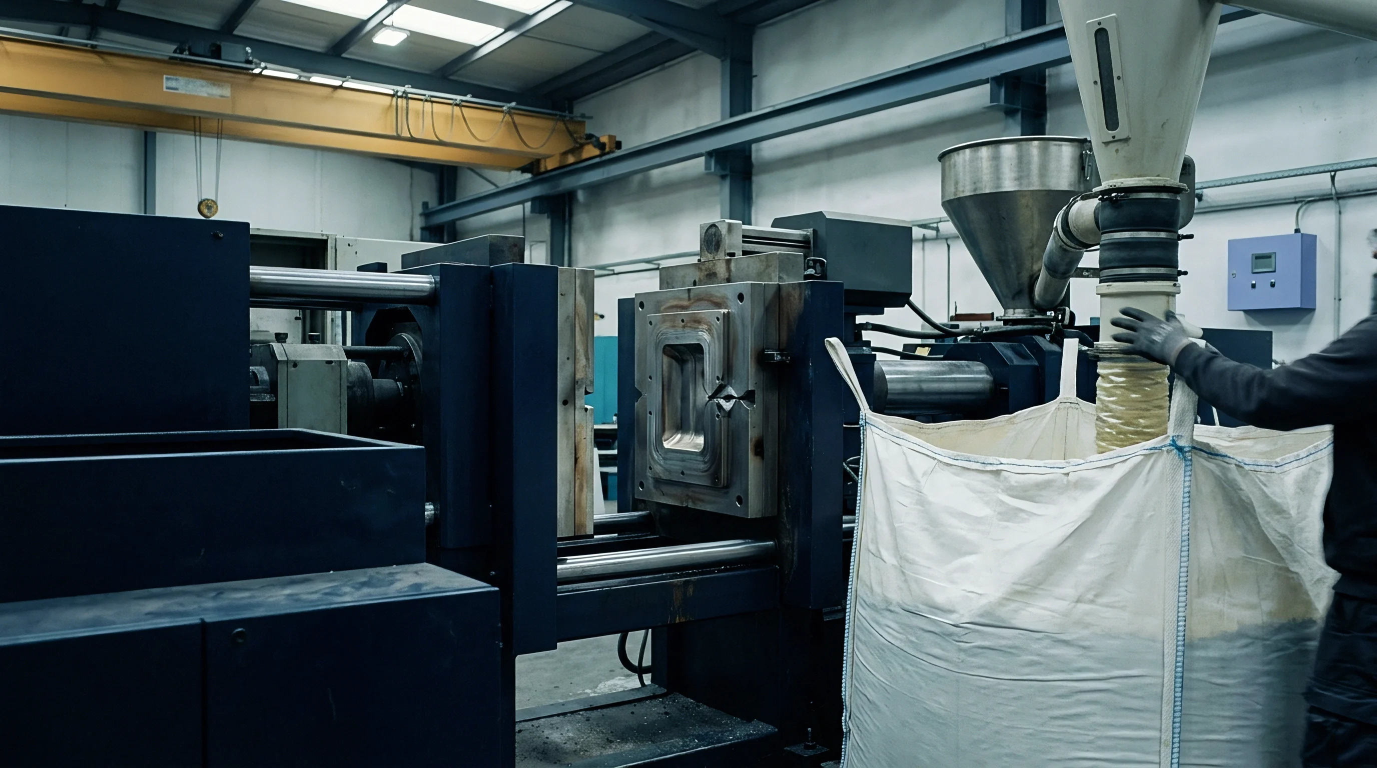

Strand
Short glass reinforcement suspended in semi-crystalline polyamide melt alters isotropic contraction into directional volumetric change. Unreinforced polyamide 66 exhibits volumetric shrinkage between 1.5% and 2.0%, distributed uniformly across longitudinal and transverse axes during polymer chain crystallization. Adding 30% by weight short glass fibers restricts thermal contraction along the fiber longitudinal axis while leaving transverse matrix contraction largely unconstrained.
Parallel shrinkage along the primary melt vector drops to a range of 0.2% to 0.5%, whereas transverse shrinkage across flow lines remains between 0.7% and 1.2%. This structural divergence establishes an anisotropy ratio spanning 2.0 to 3.5, driving out-of-plane warpage and assembly distortion in thin-walled housings.
Glass strands align along melt streams. Shear profiles dictate fiber tilt. Polymer molecules crystallize around stiff inorganic fillers, creating localized residual stress fields.
When the mold cavity opens, differential stress release forces planar surfaces into parabolic curves.
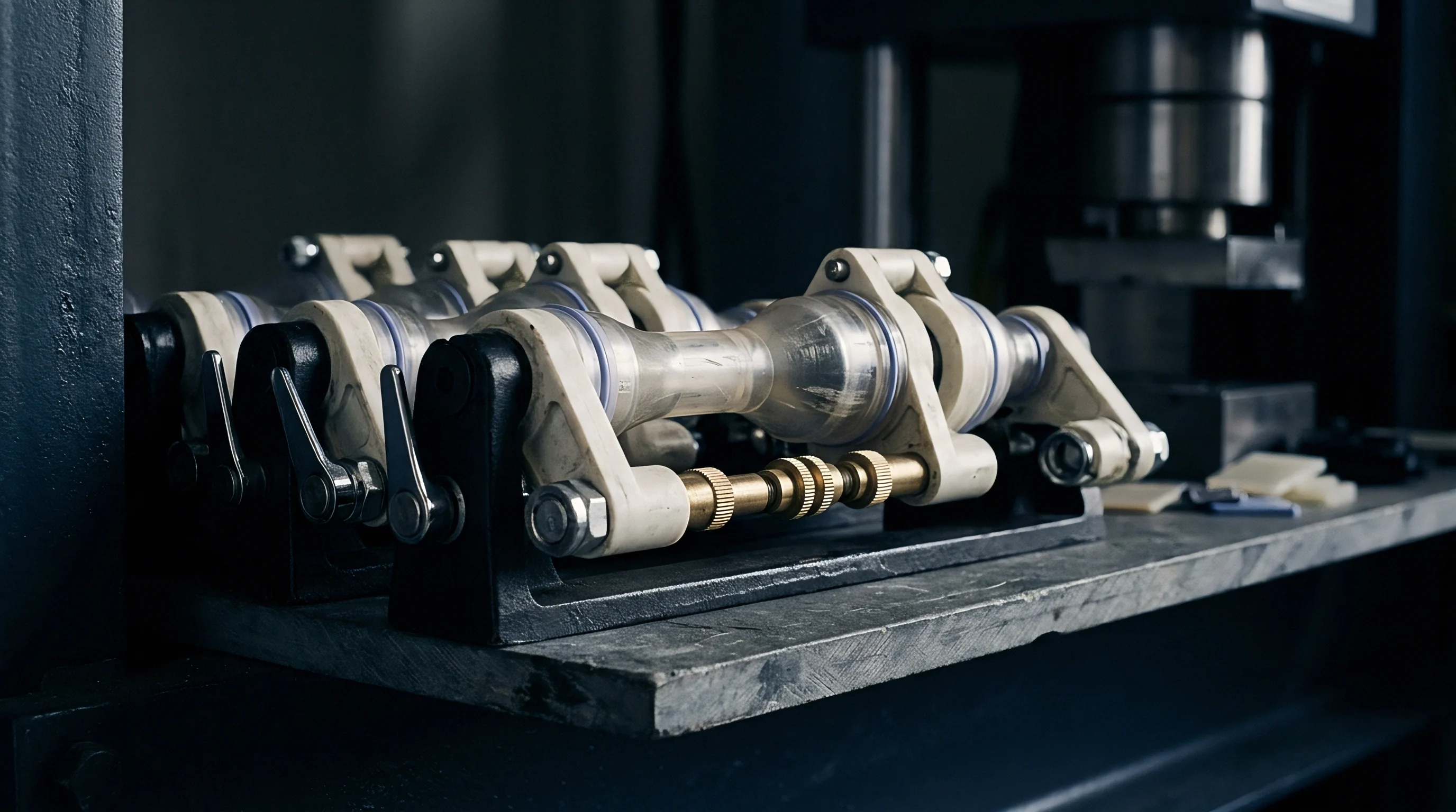
Fountain Flow Kinematics and Fiber Alignment
Extensional velocity profiles at the advancing fluid front force glass reinforcement into rigid orientation along cavity steel walls. As molten polyamide enters a cold tool, the high-shear boundary layer near the frozen surface aligns fibers parallel to the flow direction. This mechanism forms a highly oriented skin layer on both outer surfaces of the part.
Internal melt velocity gradients slow toward the center of the wall thickness, where extensional shear vanishes and transverse thermal gradients dominate. The central core layer retains a randomized or cross-flow fiber orientation, yielding a sandwich structure with contrasting mechanical and thermal characteristics across its thickness profile.

Skin Core Layer Ratios across Wall Thicknesses
Polymer solidifying against cold steel freezes highly oriented surface zones while the central core remains randomized by transverse shear. In a 2.0 mm wall section, skin layers account for approximately 60% of total thickness, dominating overall dimensional shrinkage toward the flow direction. Increasing nominal wall thickness to 4.0 mm expands the central core ratio to nearly 60% of total volume, elevating average transverse shrinkage and shifting the net anisotropy ratio closer to unity.
Thin nominal walls amplify flow-direction fiber alignment, producing low longitudinal shrink alongside severe transverse bowing across wide planar spans.
Whether molecular chain orientation within the amorphous domains contributes independently to transverse movement under elevated tool temperatures remains unresolved by current acoustic birefringence measurement techniques.


Layout
Positioning entry ports determines the dominant orientation vectors throughout a structural mold cavity. Melt traveling from a gate toward thin wall extremities follows the path of least hydraulic resistance, establishing spatial variations in velocity gradients that dictate local fiber alignment. Diverging flow paths cause glass filaments to align along radial streamlines, generating non-uniform shrinkage fields between inner gate areas and outer flow boundaries.
Linear edge gating creates parallel flow vectors across rectangular geometry, whereas multi-point gating creates complex weld lines where converging melt fronts turn fibers perpendicular to primary flow streams.

Gating Position and Flow Front Symmetry
Centrally located pin gates generate radial velocity distribution, driving orientation outwards toward outer edges. Radial expansion aligns short glass fibers circumferentially, causing the transverse shrinkage vector to act along the radial distance from the sprue. Concentric rings shrink more than radial spokes, converting flat circular discs into conical shapes upon thermal equilibration.
Submerged gates and edge gates align fibers along linear vectors, preserving straight edges along the primary axis while producing transverse narrowing across the part width.

Rib Architecture and Thickness Transitions
Internal stiffeners generate localized shear zones that disrupt primary melt streams. Melt flowing past a rib intersection splits into secondary flow channels, turning fiber orientations into the rib cavity and creating a localized cross-flow zone on the opposing show surface. Wall thickness steps exceeding 25% introduce differential cooling rates, where thick sections hold high heat content and extend crystallization times.
High localized shrinkage at rib roots pulls outer skins inward, compounding structural bowing with sink marks.
| Gate Configuration | Parallel Shrinkage Range (%) | Transverse Shrinkage Range (%) | Warpage Tendency | Machining Complexity |
|---|---|---|---|---|
| Single End Edge Gate | 0.25 to 0.40 | 0.80 to 1.10 | High parabolic bowing | Low toolroom cost |
| Central Diaphragm Gate | 0.30 to 0.45 | 0.70 to 0.90 | Low symmetrical expansion | High insert complexity |
| Symmetrical Fan Gate | 0.20 to 0.35 | 0.85 to 1.15 | Moderate cross-wise narrowing | Moderate runner machining |
| Sequential Valve Gate | 0.30 to 0.50 | 0.65 to 0.85 | Low localized stress | High hot runner expenditure |
Placing a single edge gate on a long planar reinforced component causes parabolic bowing, requiring steel welding and re-milling that doubles initial tooling alteration expenditures.


Pack
Applying pressure during the cooling stage compensates for volumetric contraction by forcing additional melt into solidifying core sections. Second-stage packing profiles alter internal density distributions, counteracting thermal contraction before gate freeze occurs. High holding pressure forces additional molten material into central core zones, compressing amorphous polymer chains and densifying randomized fiber regions.
Extending pack time packs extra mass into transverse spaces, which reduces transverse shrinkage values from 1.0% down to 0.6% without significantly altering flow-parallel shrinkage.
Gate freeze terminates pressure packing. Cavity pressure sensors track freeze time. Once the gate freezes, additional machine pressure yields no dimensional change inside the mold.

Hold Pressure Dynamics and Cavity Densification
Pressure transmission along the flow length decays rapidly once outer frozen skins thicken. Near the gate, cavity pressure remains high throughout the holding phase, yielding maximum core densification and minimal transverse contraction. At distant fill extremities, pressure drops due to fluid friction through narrow melt channels, resulting in lower local density and higher transverse shrinkage.
Maintaining a flat cavity pressure profile across all tool zones requires controlled packing pressure steps that match local solidification rates.

Why Do Fibres Reorient during Cavity Packing?
Melt displacement into compressing internal voids during second-stage pressure applications shifts semi-frozen glass fill along pressure gradients. High packing pressure forces molten core material forward through semi-solidified outer layers, shear-deforming the central layer and aligning core fibers closer to the primary flow vector. Lowering hold pressure leaves core fibers in randomized states, increasing transverse resistance to thermal contraction while elevating parallel thermal shrinkage slightly.
Extending hold pressure past gate freeze increases gate area stresses without altering part dimensions.
| Mold Temperature (°C) | Hold Pressure (bar) | Injection Speed (mm/s) | Parallel Shrink (%) | Transverse Shrink (%) | Anisotropy Ratio |
|---|---|---|---|---|---|
| 80 | 400 | 50 | 0.38 | 1.05 | 2.76 |
| 80 | 800 | 50 | 0.28 | 0.72 | 2.57 |
| 120 | 400 | 50 | 0.42 | 1.18 | 2.81 |
| 120 | 800 | 50 | 0.31 | 0.78 | 2.51 |
| 120 | 800 | 120 | 0.25 | 0.82 | 3.28 |
Increasing second stage packing pressure consistently reduces transverse wall variance while high tool surface temperatures increase absolute parallel contraction.


Swell
Atmospheric moisture absorption into polyamide matrix structures induces physical volumetric expansion that offsets initial thermal contraction. Polyamide 66 contains polar amide groups within its molecular backbone that attract water molecules under ambient environmental exposure. Ingested water acts as a plasticizer, expanding amorphous intermolecular spaces and increasing physical part dimensions over time.
Dry-as-moulded components measured immediately after ejection exhibit baseline thermal shrinkage dimensions. After reaching moisture equilibrium at 23°C and 50% relative humidity, PA66 absorbs roughly 2.0% water by weight, resulting in linear dimensional expansion of 0.2% to 0.3% that counteracts original thermal shrink.
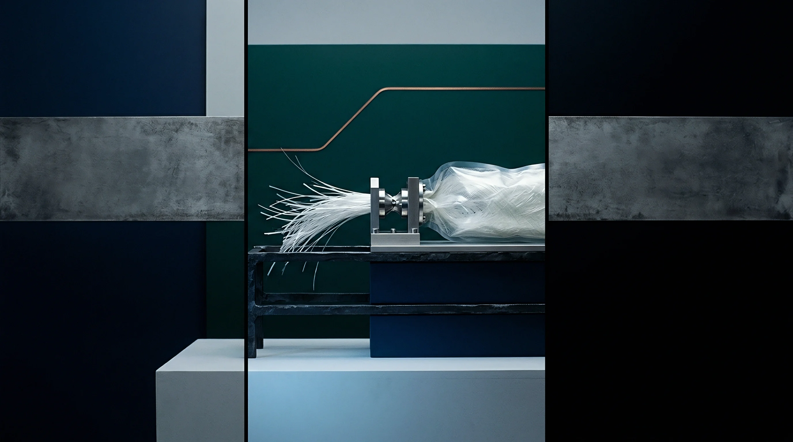
Hygroscopic Equilibrium and Dimensional Expansion
Water molecules hydrogen-bond to amide groups within the amorphous polymer regions, driving chain separation. Dimensional growth occurs isotropically within the matrix polymer phase, independent of glass fiber alignment vectors. Atmospheric water absorption expands transverse dimensions by the same percentage as parallel dimensions.
Because transverse thermal shrinkage is significantly higher than parallel thermal shrinkage, uniform moisture swelling mitigates overall volumetric anisotropy, bringing net post-conditioning dimensions closer to baseline drawing nominals.
Water ingress expands amorphous chains. Dry parts dimensions drift over time. Planar warpage ruins housing seals.

Moisture Conditioned Tolerancing Protocol
Establishing stable part geometries requires controlled humidification chambers set to standard ambient humidity before assembly checks. Measuring components dry-as-moulded yields smaller dimensional values that fail standard drawing tolerances calibrated for operational states. Mold designers scale cavity dimensions to account for post-moulding moisture expansion, preventing interference binding once parts reach environmental stability in the field.
Parts specified under ISO 294-4 require dimensional verification precisely twenty four hours after moulding unless environmental conditioning protocols are explicitly written into the procurement specification.
Failure modes of unconditioned PA66 parts installed in tight assembly housings:
- Dimensional Interference Binding occurs when components moulded dry expand during atmospheric exposure, jamming sliding mechanisms.
- Post Mold Warpage Shift arises when uneven wall moisture exposure creates moisture gradients that distort previously flat surfaces.
- Pin Retainer Buckling happens because localized volume growth generates compressive hoop stresses around metal inserts.
The moulder claimed the binding assembly was dimensionally compliant because measurements were recorded five minutes after part ejection prior to factory floor atmospheric exposure.


Gauge
Measuring directional dimensional variation in fiber-filled polymers requires explicit alignment with localized melt directions. Standard coordinate measuring machine inspections using arbitrary Cartesian alignment axes conflate transverse thermal shrinkage with flow-parallel contraction, yielding unreliable compensation figures for tool geometry modifications. Optical 3D scanning protocols map surface deviations against native CAD models, separating planar bending components from true linear shrinkage vectors along specific flow channels.

ISO 294 Standard Test Plaques versus Complex Geometry
Standardized square mold cavities provide baseline isotropic shrinkage data that rarely mirrors real-world part behavior. ISO 294-4 specifies 60 mm by 60 mm by 2 mm plaques gated across an entire edge to produce uniform linear melt streams. Industrial components feature varying wall thicknesses, internal ribs, and restricted pin gates that disrupt linear flow, rendering standard datasheet shrink values inaccurate for direct tool steel cavity sizing.
A thirty percent glass reinforced polyamide holding a fifty millimeter nominal feature achieves a tolerance of plus or minus zero point one two millimeters under DIN 16742 class TG4 when tool temperatures are controlled within two degrees Celsius.

DIN 16742 Tolerance Class Selection for Reinforced Polyamides
International tolerancing standard specifications categorize achievable dimensional precision based on material stiffness and cavity complexity. Class TG4 represents high-precision tooling execution requiring tight press parameter windows, while TG6 accommodates wider commercial production spreads. Precision reinforced polyamide mouldings achieving TG4 requirements demand tight mold surface temperature control alongside scaled cavity steel inserts calculated with localized directional shrinkage factors.
Establishing shrinkage corrections on a T1 tool sampling involves a structured verification sequence:
- CMM Alignment Point Definition establishes primary datum planes based on functional assembly interfaces rather than arbitrary part features.
- 3D Optical Scanning Comparison overlays full field volumetric point clouds against native CAD models to isolate planar twist from linear shrink.
- Directional Vector Segregation separates linear dimensions parallel to local melt vectors from transverse cross-flow features.
- Steel Recut Calculation applies differential scale factors to cavity inserts before wire EDM or milling operations occur.
| Molded Part Dimension (mm) | Tolerance TG4 (mm) | Tolerance TG5 (mm) | Tolerance TG6 (mm) | Process Requirement |
|---|---|---|---|---|
| 1 to 6 | ±0.05 | ±0.08 | ±0.12 | Closed-loop cavity pressure tracking |
| 6 to 30 | ±0.09 | ±0.14 | ±0.22 | Mold temperature uniformity ±2°C |
| 30 to 120 | ±0.17 | ±0.26 | ±0.40 | Directional shrinkage steel compensation |
| 120 to 400 | ±0.35 | ±0.52 | ±0.80 | Conditioned dimensional stabilization |
Incorporating clause 4.2 of DIN 16742 into the procurement contract shifts the financial responsibility for secondary steel modification to the toolmaker if T1 samples exceed class TG5 limits.


Calculus
Translating differential polymer shrinkage dynamics into tooling budgets requires balancing upfront toolmaking precision against post-trial modification expenses. Machining cavity steel using a single isotropic shrinkage scaling factor guarantees dimensional failure across cross-flow features on first tool trials. Correcting out-of-tolerance cavities by removing metal via CNC milling or electrical discharge machining costs far less than fixing undersized areas through welding or insert replacement.

Steel Safe Design Strategy for Anisotropic Cavities
Cutting mold steel under conservative dimensional assumptions preserves the option to remove additional metal after evaluating T1 parts. Toolmakers apply high transverse shrinkage scale factors to cavity walls while applying low parallel scale factors to internal core pins. This steel-safe approach ensures initial T1 samples remain slightly heavy or undersized in key internal bores, allowing final dimensional tuning through straightforward metal removal operations without requiring expensive laser welding or tool scrap rebuilds.
Steel alterations carry financial risk. Tool recuts delay production start.

Amortisation and Scrap Risk in Multi Cavity Production
Scaling cavity counts from single impression prototypes to high volume production tools compounds dimensional variation across parting lines. In an eight-cavity tool moulding PA66-GF30 auto electrical connectors, thermal imbalances between inner and outer runner channels alter gate freeze timing, creating cavity-to-cavity shrinkage variations. Uncontrolled anisotropic warpage elevates scrap rates, consuming project margins through secondary sorting and CMM reinspection costs.
Predictive mold filling simulation reduces steel recut cycles but cannot eliminate press side process adjustments during initial tool qualification.
Tooling qualification guidelines for controlling anisotropic distortion:
- Specify differential shrink rates separately for flow-parallel and flow-transverse dimensions in the tool design brief.
- Implement steel-safe dimensions on all critical core pins and cavity walls prior to initial CNC milling.
- Mandate gate seal analysis and cavity pressure monitoring during T1 press trials before approving tool geometry.
- Perform moisture conditioning on initial off-tool samples before final CMM sign-off against drawing limits.
| Modification Strategy | Initial Tooling Cost (USD) | Recut Iteration Cost (USD) | Time to Production (Weeks) | Expected Scrap Rate (%) |
|---|---|---|---|---|
| Isotropic Shrink Average | 65,000 | 14,500 | 18 | 4.5 |
| Steel Safe Directional Compensation | 72,000 | 2,200 | 13 | 0.8 |
| Full hot runner valve gate control | 98,000 | 1,500 | 12 | 0.3 |
| Assumes a 4-cavity tool producing 250,000 structural automotive PA66-GF30 components annually over a 3-year amortisation schedule. | ||||
Tooling modification budgets that account for differential contraction from the outset protect project margins against costly press downtime and unbudgeted toolroom rebuilds.