Calculating Specific Mold Cavity Dimensions Based on Material Shrinkage Variance Parameters
Calculate mold cavity dimensions using ISO 294-4 divisor formulas biased toward steel-safe limits to absorb material shrinkage variance before machining.


Offset
A toolmaker pulling a first article trial part from an injection press reads an outside caliper span of 99.24 millimeters against a drawing callout of 100.00 millimeters plus or minus 0.10 millimeters. The tool steel pocket measures exactly 101.00 millimeters, machined on the assumption of a flat one percent volumetric contraction. That single discrepancy scraps the cavity block.
The resin shrank 1.74 percent under actual press conditions because holding pressure decayed across the melt path before the gate froze.
Tool designers calculate cavity steel measurements by applying an expansion multiplier to the nominal part geometry. Two mathematical formulations exist across machine shops, generating conflicting cut sizes when resin contraction exceeds nominal estimates. The conventional linear multiplier calculates steel size by multiplying the desired molded feature size by one plus the expected contraction percentage:
Steel Size = Part Size × (1 + S)
The inverse divisor formulation derives steel size from the physical definition of shrinkage recorded in ISO 294-4, where shrinkage represents the difference between tool cavity size and part size divided by the tool cavity size:
Steel Size = Part Size / (1 – S)
At a nominal contraction value of 0.005 (0.5 percent for unfilled polycarbonate), the difference between the two equations on a 100.00 millimeter feature equals 0.0025 millimeters, which fits within standard wire EDM machining errors. At a contraction value of 0.025 (2.5 percent for unfilled high-density polyethylene), the linear formula yields 102.50 millimeters while the divisor formula yields 102.564 millimeters. That 0.064 millimeter gap consumes more than half of a DIN 16742 Grade 4 tolerance window before the mold base even enters the press platens.
The steel cut remains permanent.
| Resin Type | Shrinkage Factor (S) | Linear Formula (mm) | Divisor Formula (mm) | Delta (mm) |
|---|---|---|---|---|
| Polycarbonate Unfilled | 0.006 | 100.600 | 100.604 | 0.004 |
| ABS General Purpose | 0.008 | 100.800 | 100.806 | 0.006 |
| Polyamide 66 Dry As Molded | 0.015 | 101.500 | 101.523 | 0.023 |
| Polypropylene Homopolymer | 0.018 | 101.800 | 101.833 | 0.033 |
| High Density Polyethylene | 0.025 | 102.500 | 102.564 | 0.064 |
| Polyoxymethylene Copolymer | 0.030 | 103.000 | 103.093 | 0.093 |
Molded feature sizes disperse across a bell curve governed by raw material variance and press fluctuation. When an engineering drawing permits a total tolerance bandwidth of T, and the resin contraction varies between a minimum value Smin and a maximum value Smax across production campaigns, the process consumes a specific portion of that design margin directly through volumetric drift. The span of part size variation caused purely by material shrinkage equals the cavity steel size multiplied by the difference between Smax and Smin.
Selecting the nominal cavity cut based on the midpoint of the contraction range centers the manufacturing distribution only if the material contraction parameters remain normally distributed around that target value.
Polypropylene homopolymer displays transverse contraction of 1.85 percent at 80 megapascals pack pressure, falling to 1.15 percent when packing reaches 120 megapascals.
Tooling engineers follow a sequential procedure when establishing cavity cuts for tight-tolerance components:
- Molded feature isolation establishes whether the geometry forms an external boundary governed by cavity blocks or an internal aperture governed by core pins.
- Contraction band identification extracts the minimum, nominal, and maximum shrink rates from verified plaque trials rather than raw material sales sheets.
- Cavity formula selection fixes either the linear or divisor equation as the binding mathematical standard across all computer-aided manufacturing toolpaths.
- Tolerance consumption calculation evaluates whether the shrinkage span exceeds seventy percent of the total allowable part tolerance.
- Steel sizing bias application shifts the target machining value toward the material condition that allows corrective metal removal during tool qualification.
Mistaking the mathematical basis of cavity expansion strips the mold maker of corrective options, resulting in an unrecoverable tool block that requires complete CNC replacement or laser cladding on critical sealing shutoffs.
Vector
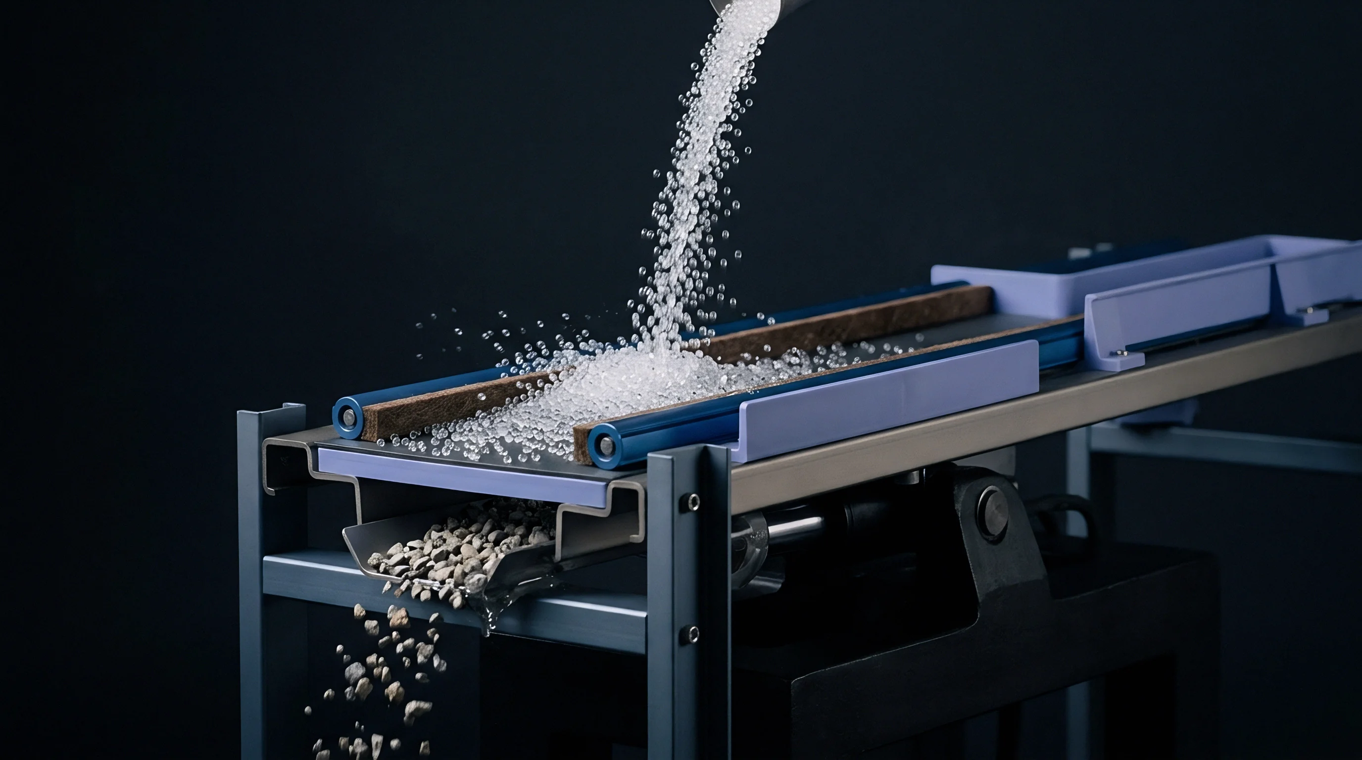
Melt entering an injection mold cavity does not behave as an isotropic fluid. Polymer chains stretch along the direction of flow, aligning under shear stress as the melt front advances across cold tool surfaces. In unfilled amorphous polymers, this orientation relaxes partially if cooling rates remain slow, but semicrystalline matrices freeze orientation into their solid lamellar structures.
Reinforced compounds carrying chopped glass fibers exhibit extreme directional divergence. The rigid fibers cannot compress or contract thermally; they align parallel to flow vectors inside high-shear boundary layers and orient randomly or transversely in the slower central core.
Glass fibers orient along flow vectors.
Linear shrink values rarely stay uniform. Along the melt path, fiberglass reinforces the matrix, dropping longitudinal contraction in a thirty percent glass-filled polyamide 66 down to 0.25 to 0.50 percent. Transverse to the melt path, where mechanical reinforcement depends almost entirely on the unreinforced base resin, contraction climbs to 0.90 to 1.30 percent.
A tool designer who applies an averaged shrink factor of 0.60 percent across all cavity axes cuts the longitudinal features too large and the transverse features too small. The resulting part emerges both out of round and bowed across flat walls.

Anisotropic Shrinkage along Flow Paths
Flow geometry determines the local contraction rate at every point within the mold cavity. Near the gate, high melt temperatures and intense packing pressure maximize density, which suppresses volumetric contraction. Far from the gate, melt pressure drops through viscous dissipation, leading to lower packing and higher shrinkage.
When gating a long rectangular box from one end, the material contracts unevenly from front to back, introducing trapezoidal distortion into what the blueprint specified as parallel walls.
| Polymer Matrix | Filler Type By Weight | Flow Shrinkage Range (%) | Cross Shrinkage Range (%) | Anisotropy Ratio |
|---|---|---|---|---|
| Polycarbonate | Unfilled | 0.50 to 0.70 | 0.55 to 0.75 | 1.07 |
| ABS Resin | Unfilled | 0.40 to 0.70 | 0.45 to 0.75 | 1.09 |
| Polybutylene Terephthalate | Unfilled | 1.50 to 2.00 | 1.60 to 2.10 | 1.06 |
| Polybutylene Terephthalate | 30% Glass Fiber | 0.30 to 0.50 | 1.20 to 1.60 | 3.43 |
| Polyamide 66 | Unfilled | 1.20 to 1.80 | 1.40 to 2.00 | 1.14 |
| Polyamide 66 | 30% Glass Fiber | 0.25 to 0.50 | 0.80 to 1.20 | 2.78 |
| Polypropylene | 20% Talc Filled | 0.90 to 1.20 | 1.10 to 1.50 | 1.24 |
Transverse contraction doubles longitudinal values. When calculating the cavity geometry for an anisotropic part, the CAD programmer assigns distinct Cartesian scaling factors along the major flow axes. The toolroom cuts the X-axis pocket at 100.35 millimeters and the Y-axis pocket at 101.10 millimeters to achieve a finished square part of 100.00 by 100.00 millimeters.
If the gate shifts by even five millimeters during tool revisions, the flow angle rotates, rendering the directional offsets incorrect.
Flow alignment pulls shrink rates lower along the melt direction while transverse contraction expands.

Where Does Crystallization Kinetics Alter Volumetric Compaction?
Thermodynamic cooling curves dictate how polymer chains organize into crystalline spherulites. Rapid cooling freezes the polymer melt before polymer chains fold into tight crystal structures, creating lower material density and lower overall contraction. Slow mold cooling allows extended molecular reorganization, generating dense crystalline domains that pull the polymer walls inward.
Running an injection mold at sixty degrees Celsius produces an entirely different finished part size than running the same steel at ninety degrees Celsius, even when injection speed and pack pressures remain identical.
The operational failure modes stemming from poorly managed shrinkage vectors disrupt assembly lines in repeatable patterns:
- Corner warpage occurs when differential contraction across intersecting ribs forces vertical walls to pull inward past draft allowances.
- Hole ovality develops whenever radial melt paths cross circular core pins, causing unequal hoop stress around the pin circumference.
- Planar saddle bowing manifests in flat covers where center-gated flow creates compressive hoop stresses along peripheral edges.
- Weld line grooving surfaces at flow confluence zones where frozen skin layers contract away from adjacent melt fronts without adequate packing pressure.
Molecules freeze under directional shear. Semicrystalline polymers exhibit secondary post-molding shrinkage that continues for forty-eight hours following ejection as latent crystallization completes. A part measuring within specification five minutes off the press shrinks another 0.20 percent before packaging if internal thermal energy stays trapped inside stacked totes.
Melt fronts that travel around corners contract toward the anchor point of highest wall thickness.


Gate
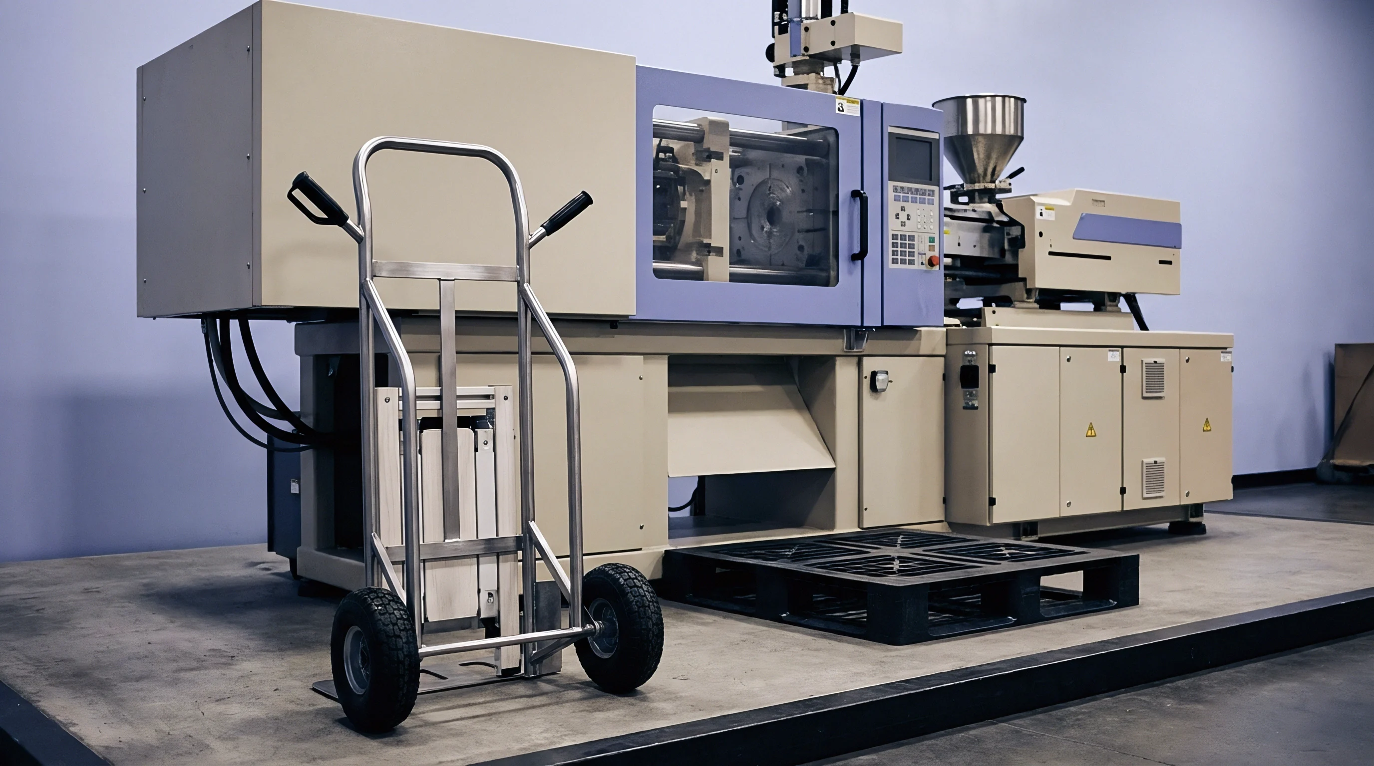
Fluid pressure inside the cavity governs the final mass of polymer packed into the available tool volume. Hydraulic or electric screw pressure drives melt through the sprue, runner, and gate orifice, but friction strips hydraulic force at every transition. When the screw holds ninety megapascals of specific pressure at the nozzle, pressure inside the cavity typically drops to fifty megapascals near the gate and twenty megapascals at the end of the fill path.
Because volumetric contraction correlates inversely with cavity packing pressure, a molded part contracts substantially less near the gate than at its farthest geometric boundary.
Holding pressure determines final density.
The gate orifice serves as a thermal valve. Melt flows into the cavity until the narrow cross-section of the gate chills below the no-flow temperature of the polymer. The moment gate freeze occurs, the screw can no longer transfer mass into the cavity.
Any residual contraction occurring within the cooling polymer matrix can no longer be offset by packing pressure. The part volume shrinks against its enclosed steel boundaries, generating internal tension that pulls surfaces away from cavity walls.

Packing Pressure Decay across Flow Length
Thick sections feed melt longer. Thin walls freeze almost instantly. If a thin wall section sits between the gate and a thick boss, the thin section freezes premature to the boss, isolating the thick zone from packing pressure.
The isolated boss then contracts at its maximum natural volumetric shrinkage rate, pulling sink marks into opposing cosmetic surfaces or creating internal vacuum voids. Toolmakers resolve this by routing melt through heavy wall sections into thinner ribs, allowing the holding pressure to pack the tool progressively until all gates seal.
ISO 294-4 dictates plaque measurement after forty-eight hours at twenty-three degrees Celsius, penalizing suppliers whose shop-floor callouts rely on immediate ejection readings.
Cavity transducers expose freeze transitions. By embedding piezoelectric pressure pins flush with the cavity surface directly behind the gate and near the end of fill, process engineers record the precise millisecond of gate freeze. If the packing timer cuts off before the transducer curve levels off, melt backflows into the runner system, causing sudden volumetric expansion inside the runner and elevated contraction inside the part.

Runner Geometry Influence on Frozen Volume
Runner sizing controls pressure transmission efficiency. Cold sub-runners drop melt temperature rapidly, increasing resin viscosity before the cavity fills completely. Hot runner manifolds maintain constant melt temperatures directly to the cavity gate, allowing higher cavity pressures under lower injection unit loads.
Switching a mold design from a cold runner edge gate to a hot runner valve gate drops the material contraction factor by fifteen to twenty-five percent because hot tips pack cavities more effectively.
Tool builders review critical gating parameters prior to releasing manufacturing blueprints:
- Gate depth verification ensures the entry orifice equals at least sixty percent of the nominal nominal wall thickness to prevent premature gate freezing during packing phases.
- Flow length ratio calculation confirms that melt travel distances remain within published spiral flow limits for the selected resin grade at baseline injection pressures.
- Pressure drop modeling simulates whether hydraulic gradients between gate and fill endpoints exceed twenty-five megapascals across the continuous part span.
- Cooling channel alignment checks that dedicated water baffles surround hot gate inserts to extract localized thermal loads without creating hot spots.
The toolmaker who cuts a mold without calculating gate freeze timing routinely tells the buyer that the resin supplier delivered a bad batch with inconsistent melt flow rates.

Drift
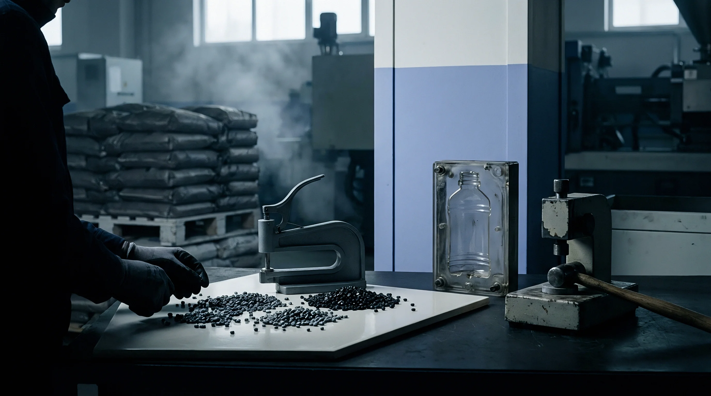
Material datasheets report shrinkage as a static decimal range, such as 0.012 to 0.018 millimeters per millimeter. That spread is not a manufacturing tolerance. It represents the variance observed across test plaques molded under disparate laboratory processing conditions.
In continuous production across three shifts, process parameters wander. Barrel heater bands cycle, ambient factory temperatures shift twenty degrees Celsius between summer and winter, and regrind ratios fluctuate as sprues re-enter the feed hopper.
Process drift destroys nominal tolerances.
Raw resin lots arrive with natural variations in molecular weight distribution. A supplier delivering unfilled polyoxymethylene guarantees a Melt Volume-Flow Rate (MVR) within a defined commercial specification band, typically plus or minus fifteen percent from nominal lot targets under ISO 1133 test conditions. A higher MVR lot flows more easily, packs to higher cavity pressures, and contracts less.
A lower MVR lot increases viscosity, causing higher pressure drops across the runner and yielding parts with greater shrinkage.

Lot Variance in Semicrystalline Resins
Every resin shipment carries viscosity spread. In a rigorous mold capability run with twenty-four-hour continuous monitoring, a five percent shift in resin moisture content transforms the dimensional capability of polyamide materials. Excess water molecules cause hydrolytic degradation in the barrel, shortening polymer chains.
The cleaved chains pack into tighter crystalline configurations, accelerating shrinkage beyond the calculated maximum steel offset.
Consider a baseline injection setup running an unfilled POM gear with a 50.00 millimeter pitch diameter. Under standard supplier baseline settings (80 megapascals pack pressure, 90 degrees Celsius mold temperature, 20 seconds cooling time), the resin contracts at 2.00 percent, requiring a cavity diameter of 51.020 millimeters. If an overnight operator drops packing pressure to 60 megapascals to eliminate minor flash, contraction rises to 2.35 percent, shrinking the gear pitch diameter down to 49.82 millimeters.
That 0.18 millimeter shift exceeds the total allowable tooth tolerance grade.
| Shrinkage Variance Band (Smax – Smin) | DIN 16742 Tolerance Group | Achievable Part Tolerance For 50 mm Span (± mm) | Achievable Part Tolerance For 100 mm Span (± mm) | Steel-Safe Sensitivity |
|---|---|---|---|---|
| ≤ 0.004 (Tight Amorphous) | TG3 | 0.08 | 0.12 | Low |
| 0.005 to 0.009 (Standard Amorphous) | TG4 | 0.11 | 0.17 | Moderate |
| 0.010 to 0.014 (Filled Semicrystalline) | TG5 | 0.16 | 0.24 | High |
| 0.015 to 0.020 (Unfilled Semicrystalline) | TG6 | 0.22 | 0.34 | Extreme |
| > 0.020 (High-Shrink Olefins) | TG7 | 0.30 | 0.46 | Critical |
| Values based on DIN 16742 capability indices using production process capability Cpk ≥ 1.33 across stable toolroom conditions. | ||||

Thermal Fluctuation across Tool Platens
Mold cooling loops develop scale deposits. Calcium carbonate buildup inside drilled water lines reduces heat transfer efficiency over months of operation. A cooling circuit that maintained sixty degrees Celsius steel on day one warms to seventy-two degrees Celsius after six months of untreated cooling tower exposure.
The elevated steel temperature retards part solidification, increasing crystallization and expanding the contracted span. The press setter adjusts injection velocity to compensate, masking thermal degradation with mechanical shear.
Data regarding long-term shrinkage drift under varying regrind ratios remains commercially disputed across the tooling sector. Moulders claim that adding twenty percent regrind changes final part dimensions by less than 0.05 percent. Bench measurements show that regrind introduces heat history that alters polymer nucleation rates unpredictably.
Sourcing engineers manage this uncertainty by specifying virgin resin limits on drawings and requiring re-qualification trials whenever regrind percentages exceed ten percent.
Will process monitoring alone ever fully decouple volumetric shrinkage from thermal tool movements across decades of mold usage?


Reserve
Cutting steel to dead-center nominal dimensions assumes zero modeling errors and perfect material predictability. Experienced mold designers do not cut to nominal. They use a steel-safe machining reserve.
This methodology positions cavity and core measurements such that inevitable shrinkage prediction errors leave excess metal on the tool rather than removing required tool steel.
Steel removed from a cavity pocket cannot be reattached without altering base metal metallurgy.
For an external feature on a molded component, such as an outer housing wall, the part shrinks inward toward its geometric center. If the resin shrinks less than predicted, the molded part emerges larger than the blueprint target. If the mold maker machined the cavity steel pocket undersized (steel-safe condition), excess metal remains in the tool pocket.
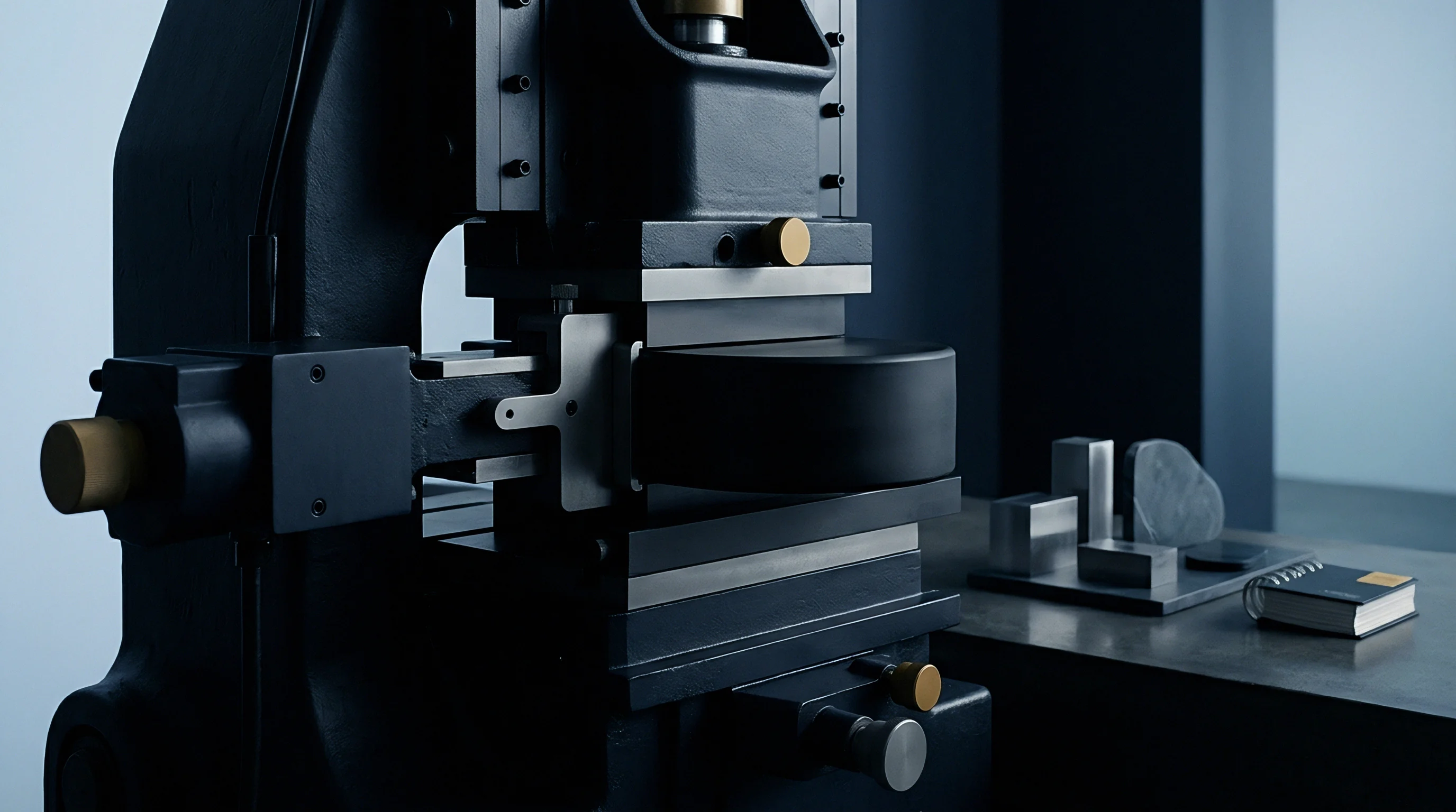
The toolmaker mounts the cavity block on a CNC machining center or EDM sinker, cuts away a few hundredths of a millimeter of steel, and enlarges the molded part to hit the target dimension. If the toolmaker had cut the cavity pocket oversized, repairing the tool would demand welding hardened tool steel, an intervention that compromises surface finish and induces internal stress cracking.
Does Steel Safe Sizing Prevent Tool Rebuilding?
Internal part features obey the inverted geometric rule. A molded hole is formed by a protruding core pin. The plastic shrinks tightly around the pin as it freezes.
If the resin shrinks less than anticipated, the molded hole ends up larger than specified. Machining the core pin oversized initially creates a steel-safe reserve. If the molded hole proves too small during first article testing, the toolmaker mounts the core pin in a cylindrical grinder and removes steel from its outer diameter.
Grinding the pin smaller allows the molded plastic to contract into a smaller hole diameter, correcting the defect through basic subtractive machining.
Welding tool cavities degrades base hardness.
The standard procurement approach for tools running high-variance semicrystalline resins specifies a two-stage steel release protocol. Cavity blocks are cut to the lower limit of expected shrinkage, while core pins are machined to the upper limit. After shooting fifty prototype parts under production-intent process windows, optical coordinate measuring machines map dimensional deviations across all axes.
The resulting error vector field directs a secondary subtractive machining pass that brings out-of-tolerance features into center-spec alignment.

Tolerance Capability Budget under DIN 16742
Recutting steel costs time and capital. DIN 16742 provides an engineering standard that protects buyers and mold makers from unworkable tolerance allocations. The standard establishes tolerance groups (TG1 through TG9) based on the inherent shrinkage variance of the chosen polymer matrix.
Attempting to hold a TG3 tolerance grade on an unreinforced polypropylene homopolymer guarantees continuous part rejection; the natural material shrinkage variance exceeds the total allowable design bandwidth.
Toolmaker margins vanish on rework.
Commercial contracts protect the buyer by incorporating the acceptance criteria of DIN 16742 Section 7, which dictates that tooling signoff occurs only after the supplier proves a process capability index (Cpk) of at least 1.33 on all critical-to-function dimensions over an uninterrupted production run of three distinct material lots.