Predicting Anisotropic Creep Fatigue Damage Coupling at Thermoplastic Weld Line Microstructural Interfaces
Predict anisotropic creep-fatigue weld failure by mapping orientation tensors from fill models into CDM solvers with experimental notch factors.

Melt
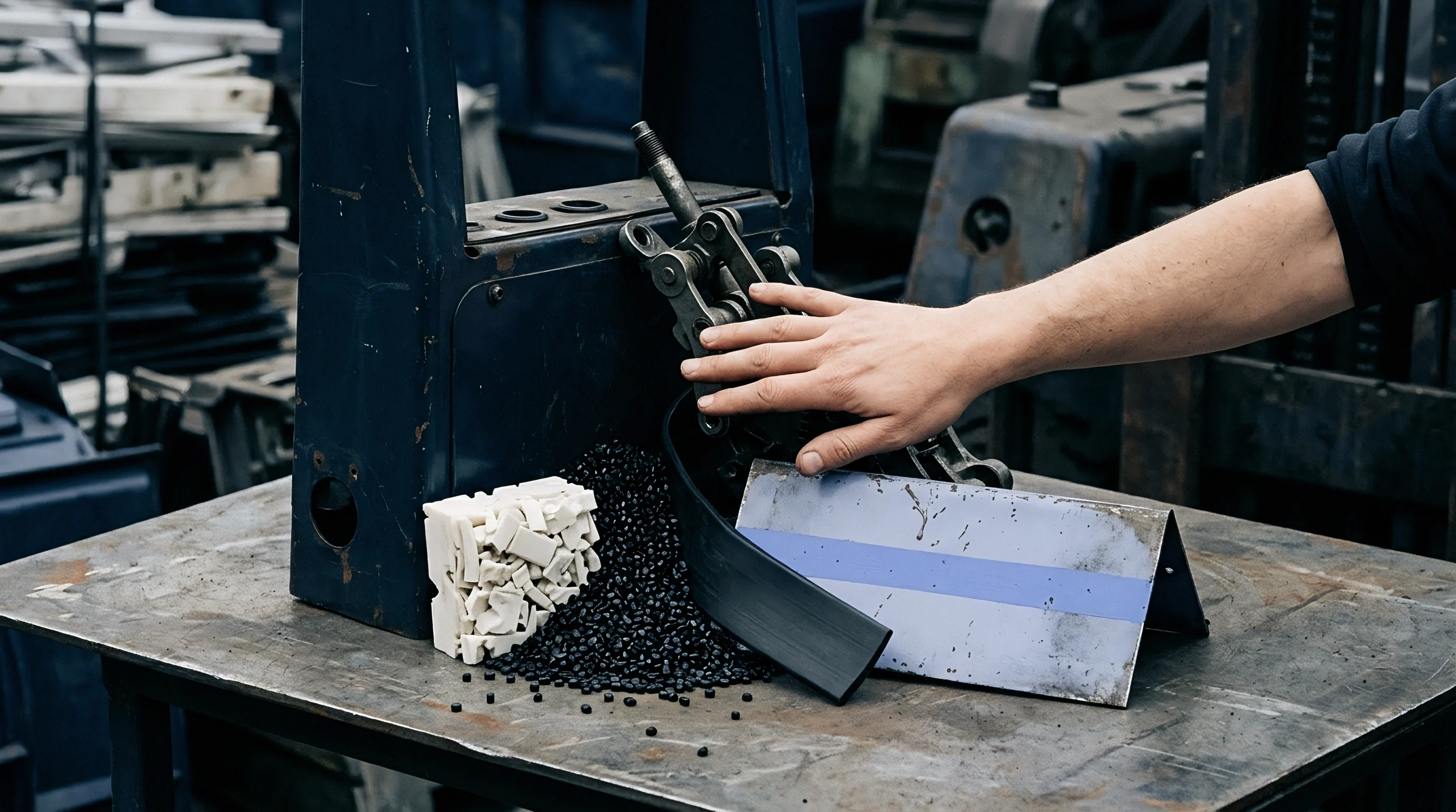
Fluid convergence during injection molding forces polymer chains and reinforcement fibers into parallel alignment along colliding flow fronts. When two melt fronts meet inside a tool cavity, fountain flow mechanics push the cooler, semi-solid outer material into the center of the impinging boundary. This mechanical collision creates a distinct planar boundary through the cross-section of the part.
In unreinforced neat polymers, the structural integrity of this line depends on molecular interdiffusion across the interface before the material cools below its glass transition temperature or crystallization window. In fiber-reinforced thermoplastics, the presence of solid glass or carbon fibers introduces severe structural anisotropy that dominates the failure mode under combined static and dynamic mechanical loads.
Viscosity spikes during packing. As the molten polymer fills the mold cavity, the advancing fronts experience rapid thermal energy loss to the cold steel walls. Lower mold temperatures sharpen the thermal gradient between the skin layer and the molten core, shrinking the thermal window available for molecular re-entanglement.
If the flow fronts meet near the end of the fill stroke where cavity pressure drops, the compressive force available to press the fronts together diminishes. Insufficient hold pressure leaves microvoids and localized unbonded regions along the seam, establishing built-in notch roots that act as permanent stress concentrations.
| Melt Temperature (°C) | Mold Wall Temperature (°C) | Hold Pressure (MPa) | V-Notch Depth (µm) | Parallel Fiber Orientation Tensor Component | Tensile Weld Line Factor (%) |
|---|---|---|---|---|---|
| 275 | 70 | 40 | 8.4 | 0.82 | 52 |
| 285 | 85 | 60 | 4.2 | 0.86 | 64 |
| 295 | 100 | 80 | 1.8 | 0.89 | 78 |
| 305 | 115 | 100 | 0.6 | 0.91 | 85 |
Kinematics of Impinging Flow Fronts
Rheological behavior at the impinging boundary dictates how molecular entanglements cross the weld plane. When advancing polymer streams collide head-on, termed a cold weld line, velocity vectors collapse to zero along the normal axis of the interface, forcing material to flow outward toward the mold cavity walls. This diverging kinematically driven lateral flow re-orients both polymer chains and high-aspect-ratio reinforcement fibers parallel to the meeting plane.
Consequently, virtually zero fibers bridge across the weld line. In contrast, weld lines formed by streams re-knitting around a core pin or internal obstacle, often designated hot weld lines or meld lines, retain a positive velocity component along the primary flow axis, resulting in slightly lower fiber misalignment and higher residual mechanical strength.
Cold flow fronts fail early. The velocity gradient across the melt front generates a strong shearing action that strips short glass fibers from the center flow stream and stacks them flat against the impinging surface. The degree of fiber orientation along the weld plane correlates directly with shear rate and melt front velocity prior to collision.
High injection speeds keep the melt front warm and reduce local shear stress, enabling better matrix interpenetration, yet high shear rates simultaneously increase the degree of anisotropic fiber alignment parallel to the seam. Process engineers must balance injection speed to optimize thermal energy retention without over-aligning fibers along the vulnerable plane.

Thermal History and Fountain Flow Effects
Polymer streams cooling below their transition threshold generate distinct structural gradients across the core. The outermost skin layer cools almost instantaneously upon contacting the tool steel, freezing high molecular orientation and trapped micro-v-notches into the component surface. Beneath this skin, the mid-wall region experiences slower cooling, permitting limited chain relaxation, while the central core stays hot longest.
However, because fountain flow continuously rolls fresh polymer from the hot core to the leading edge of the front, the weld interface receives cold material along its outer boundaries and hot material at its center. This non-uniform thermal history produces significant residual thermal stresses across the wall thickness.
- Microvoid coalescence driven by localized thermal shrinkage along un-pressurized weld planes during the cooling phase.
- Matrix degradation caused by excessive residence time at peak melt temperatures intended to force thermal re-knitting.
- Localized crystallization suppression in semi-crystalline polymers like polyamides where rapid cooling rates at the weld interface truncate spherulite growth.
- Volatile entrapment due to inadequate mold cavity venting at the exact point of flow front collision, creating micro-porosity.
Tooling vendors routinely claim that increasing hold pressure automatically eliminates weld seam weakness, ignoring the fundamental fiber alignment mismatch that remains locked into the frozen core.

Interface
Microstructural examination reveals a highly localized boundary region characterized by distinct fiber disorientation and V-notch surface geometry. Across a short distance typically spanning 50 to 200 micrometers, the orientation tensor describing fiber alignment rotates from the primary flow direction to a direction completely parallel to the interface plane. This radical structural transition converts what would otherwise be a fiber-dominated material response into a matrix-dominated region.
Under mechanical tension applied normal to the weld line, the load is carried almost entirely by the unreinforced polymer matrix rather than the high-modulus reinforcement phase.
When reinforcement fibers align parallel to a joining line rather than crossing it, mechanical strength depends entirely on unreinforced polymer matrix cohesion.
Glass fibers orient parallel here. The spatial distribution of fibers across the interface creates a distinct three-zone morphology comprising the outer skin zone, the transition zone, and the central core zone. Within the skin zone, rapid thermal quenching locks in deep V-grooves at the surface surface where air or volatilized additives are trapped.
These grooves possess sharp root radii ranging from 1 to 10 micrometers, acting as sharp mechanical notches that severely reduce the fatigue threshold under cyclic loading. The depth and sharpness of these surface V-notches dictate the stress concentration factor, which can elevate local elastic stresses to three times the nominal applied stress.
Fiber Orientation Tensor Distortions
Reinforcement fillers realign parallel to the weld plane rather than crossing it to bridge mechanical loads. Quantitative representation of fiber structure relies on the second-order fiber orientation tensor, where the component axx measures alignment along the primary flow axis and ayy measures alignment transverse to flow. At a standard location far from the weld seam, axx typically ranges between 0.70 and 0.85 for injection-molded short glass composites.
At the weld line interface, axx drops sharply to near zero, while ayy rises above 0.80. This complete reversal of the orientation tensor means the composite material loses its reinforcing efficiency precisely where structural continuity is needed most.
- Melt fronts collide and force lateral flow, rotating fiber axes by up to ninety degrees relative to the primary load vector.
- Matrix material accumulates along the center plane, forming an unreinforced polymer layer between fiber-rich boundary zones.
- Cooling differentials generate tensile residual stresses in the core zone, compounding external mechanical traction.
- External static tensile loads concentrate strain within the unreinforced matrix layer, initiating micro-plastic yielding at low stress levels.
V Notch Root Radius Morphology
Surface grooves created by trapped gas pockets act as stress risers under applied external traction. The geometry of the weld line surface groove depends on mold venting quality, melt temperature, and packing pressure. Optical profiling and scanning electron microscopy demonstrate that high packing pressures press the molten fronts tightly against the cavity steel, flattening surface irregularities and increasing the V-notch root radius.
A larger root radius reduces the local stress concentration factor Kt, directly improving fatigue life. Conversely, poor venting leaves gas trapped at the flow convergence point, forcing the root radius down to sub-micron dimensions and creating micro-cracks before any external load is applied.
V-notch roots concentrate strain. In semi-crystalline matrix polymers such as polyamide 66 or polyphenylene sulfide, the cooling rate variation at the notch tip alters local crystallinity. Rapid cooling produces a lower crystallinity matrix with reduced yield strength, whereas slower core cooling allows higher crystallinity but larger spherulite dimensions, which can facilitate inter-spherulitic micro-cracking under creep loads.
This complex interaction between surface notch geometry, local crystallinity gradients, and fiber orientation tensor shifts creates a highly heterogeneous microstructural interface vulnerable to time-dependent failure mechanisms.
High pressure closes air microvoids.
Coupling
Structural components subjected to sustained static traction alongside cyclic dynamic stresses experience synergistic degradation rate acceleration. When a creep stress is applied concurrently with cyclic fatigue loading, damage accumulates faster than predicted by linear damage superposition rules such as Miner’s sum combined with Robinson’s creep rupture rule. The physical mechanism behind this non-linear coupling at the anisotropic weld line interface involves the interplay between viscoelastic matrix flow, void nucleation around misaligned fiber ends, and microcrack propagation driven by fatigue cycles.
Under combined creep-fatigue at 120°C, short-glass PA66 weld line fatigue life drops by 68 percent compared to pure fatigue at identical peak stress amplitudes.
Matrix rich zones creep rapidly. Under static tensile load, the unreinforced matrix layer at the weld line undergoes time-dependent viscoelastic shear and tensile deformation. As the polymer matrix creeps, stress relaxes away from the ductile matrix and transfers onto adjacent fiber ends aligned parallel to the seam.
Because these fibers cannot bridge the interface, high interfacial shear stresses develop at the fiber-matrix interface. Over time, this localized stress buildup causes micro-debonding between glass fibers and the polymer matrix, nucleating microvoids long before macroscopic material yielding occurs.
| Test Temperature (°C) | Mean Creep Stress σm (MPa) | Cyclic Stress Amplitude σa (MPa) | Linear Damage Sum (Dc + Df) at Failure | Coupling Factor α | Observed Cycles to Failure Nf |
|---|---|---|---|---|---|
| 80 | 20 | 25 | 0.82 | 0.45 | 1.45 x 10⁵ |
| 80 | 35 | 25 | 0.68 | 0.72 | 6.20 x 10⁴ |
| 120 | 20 | 25 | 0.54 | 1.15 | 3.10 x 10⁴ |
| 120 | 35 | 25 | 0.38 | 1.68 | 8.50 x 10³ |
Continuum Damage Mechanics Formulations
Mathematical formulations track the growth of scalar microvoids alongside microcrack density tensor variables. Continuum Damage Mechanics (CDM) models represent the coupled state through a creep damage variable Dc and a fatigue damage variable Df. Creep damage evolution follows an orthotropic Kachanov-Rabotnov formulation modified for anisotropic material tensors:
dotDc = left( fracσeqAc (1 – Dc) right)rc · left mc
where σeq represents equivalent scalar stress, Ac and rc are temperature-dependent material parameters, mathbfn is the unit normal vector to the weld interface plane, mathbfA is the second-order fiber orientation tensor, and mc dictates the orientation sensitivity exponent. Fatigue damage evolution per cycle follows a modified Chaboche non-linear continuous fatigue damage law:
fracdDfdN = left α(σmax, σm) left( fracσmax – σl(1 – Df)M(T) (1 – Df) right)β
where σmax is peak cyclic stress, σl is fatigue endurance limit, M(T) is temperature-dependent fatigue strength parameter, and β is a material fatigue exponent. Total damage coupling integrates non-linear cross terms:
Dtotal = Dc + Df + αcf Dc Df
where αcf is the creep-fatigue damage coupling coefficient. When αcf > 0, creep cavitation accelerates microcrack growth rates during the tensile portion of each fatigue cycle, while fatigue-induced microcracks increase local creep strain rates by reducing the net load-bearing cross-sectional area.
Anisotropic Viscoelastic Creep Compliance
Time dependent strain tensors vary dramatically depending on the angle between tensile vectors and fiber alignment planes. Off-axis viscoelastic behavior requires a full fourth-order creep compliance tensor Jijkl(t, T). At the weld line interface, where fiber orientation shifts by ninety degrees relative to the surrounding parent material, compliance values along the loading direction spike significantly.
At elevated temperatures near the glass transition temperature, viscoelastic creep compliance accelerates exponentially, causing localized strain concentration within the thin weld plane.
Stress concentration multiplies fatigue damage.
During low-frequency fatigue cycles superimposed on static pre-loads, this local creep strain concentration drives cyclic plastic strain accumulation, a process known as mechanical ratcheting. Ratcheting at the weld line interface dilates microvoids surrounding misaligned fibers, turning blunt microvoids into sharp crack nuclei. These crack nuclei propagate rapidly under subsequent cyclic stress sweeps, reducing the fatigue life of the structural part by up to an order of magnitude compared to non-weld areas under identical global strain field conditions.
Whether non-linear viscoelastic creep damage models can accurately capture non-isothermal aging effects at the weld plane under complex variable-amplitude spectrum loading remains an active area of investigation.

Trial
Mechanical verification demands physical testing protocols that isolate creep strain accumulation from cyclic fatigue crack propagation rates. Standard isotropic test protocols fail to capture the localized, directional vulnerability of thermoplastic weld seams. To reliably predict long-term performance, test programs evaluate both neat parent material specimens and double-gated weld line specimens under identical thermal, static, and dynamic stress profiles across representative operational temperature bands.
ISO 899-1 creep rupture testing on dual-gated specimens establishes mandatory knock-down factors before structural tool design sign-off.
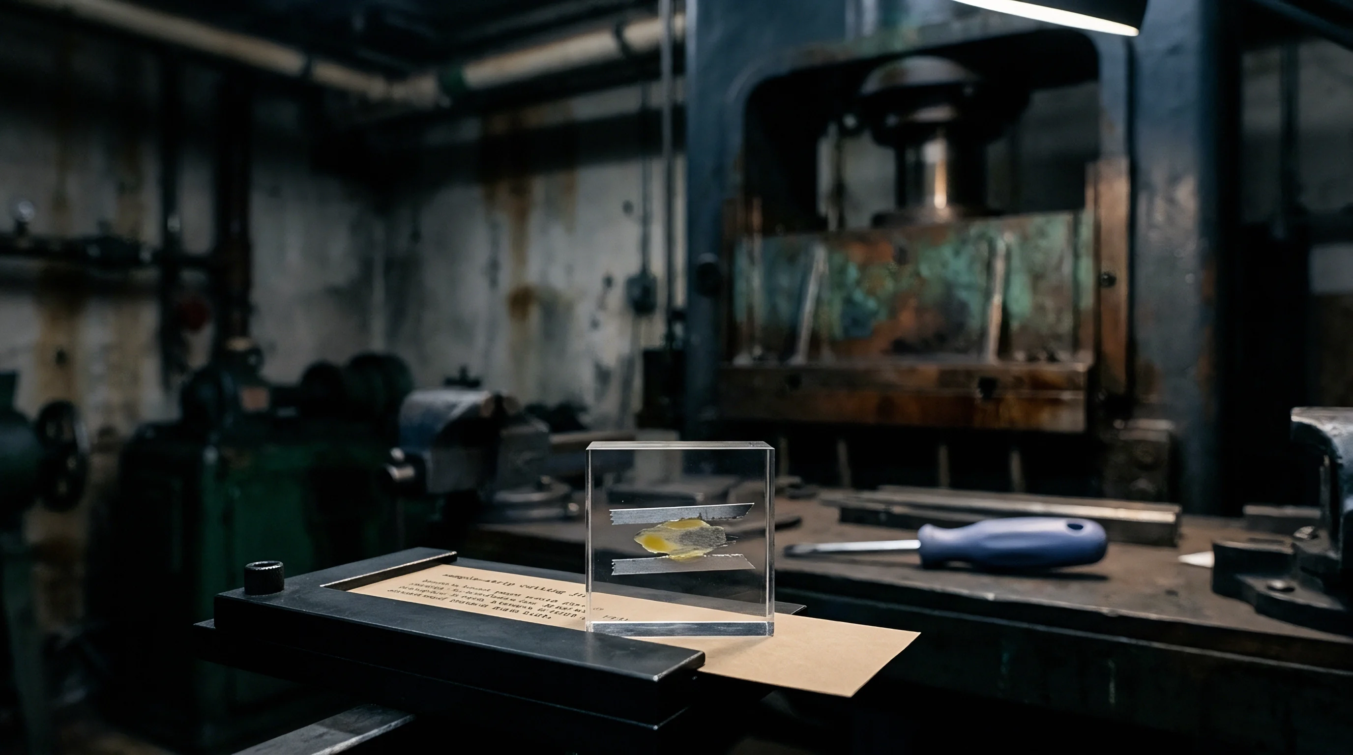
Gate placement dictates seam position. Generating repeatable, representative weld line test specimens requires precision tooling built to ISO 20753 standards equipped with dual opposing edge gates. Shutting off one gate produces pristine, fully oriented reference specimens, while opening both gates creates a perfectly centered cold weld line.
Moulders verify specimen quality using cross-sectional micro-tomography or optical microscopy to ensure the surface V-notch depth and core fiber orientation distribution match the specific processing conditions expected in production tools.
How Do Multiaxial Stress States Accelerate Interface Microcrack Nucleation?
Combined torsional and axial loading conditions drive shear failure along matrix rich planes at reduced cycle counts. Real-world components rarely experience pure uniaxial tension; underhood brackets, pump housings, and pressure vessels undergo complex multiaxial stress states. When multiaxial loads act on an anisotropic weld line interface, hydrostatic tensile stress components accelerate microvoid nucleation inside the matrix, while shear stress components drive microcrack sliding and coalescence along misaligned fiber surfaces.
Biaxial creep-fatigue testing reveals that shear stresses acting parallel to the weld plane reduce the effective fatigue threshold far more aggressively than equivalent normal stresses.
- Uniaxial creep rupture testing per ISO 899-1 under isothermal conditions to establish baseline creep compliance parameters and time-to-rupture curves.
- Tension-tension fatigue testing per ISO 13003 at multiple stress ratios (R = 0.1, R = 0.5) to construct S-N fatigue life curves for weld line interfaces.
- Superimposed creep-fatigue testing utilizing trapezoidal and sinusoidal load waveforms with variable dwell times at maximum stress to isolate time-dependent creep damage from cycle-dependent fatigue damage.
- Dynamic Mechanical Analysis (DMA) temperature and frequency sweeps to extract storage modulus, loss modulus, and glass transition temperature shifts within localized weld zones.
ISO Test Protocol Alignment
Standardized test specimens molded with opposing dual gates isolate localized seam behavior under controlled thermal conditions. ISO 899-1 defines tensile creep testing protocols, specifying strain measurement accuracy within 0.5 percent over multi-thousand-hour exposure durations. For fatigue evaluation, ISO 13003 specifies dynamic mechanical testing conditions for fiber-reinforced plastics, mandating continuous temperature monitoring of specimens to prevent self-heating thermal failure during high-frequency cyclic loading.
When testing short-glass reinforced thermoplastics at frequencies above 5 Hz, hysteretic energy dissipation can raise local specimen temperature by over 10°C, artificially softening the matrix layer and generating false creep-fatigue failure points.
First article inspection reveals seam geometry.
To eliminate thermal degradation artifacts during lab trials, dynamic testing on weld line specimens limits test frequencies to 1-3 Hz and uses real-time infrared thermography to confirm isothermal conditions across the seam plane. Comparing failure surfaces via scanning electron microscopy verifies whether failure occurred via matrix ductile tearing, fiber pull-out, or micro-crack coalescence along surface V-notches, ensuring that laboratory failure modes reflect observed field failure morphologies.
Applying ISO 899-1 stress-rupture compliance clauses to part acceptance testing forces suppliers to report weld line knock-down factors explicitly on quality certificates, eliminating undisclosed material degradation risks before tool sign-off.
Dossier
Structural analysts map process simulation output directly into non-linear finite element solvers to establish local damage accumulation rates. Accurately modeling anisotropic creep-fatigue damage coupling requires bridging injection molding process physics with structural mechanics solvers. Commercial process simulation software predicts fiber orientation tensor fields (aij), local volumetric shrinkage, temperature distribution, and surface V-notch locations throughout the part geometry.
Exporting these state variables into structural FEA tools enables element-by-element mapping of orthotropic mechanical properties.
Mapping local fiber orientation tensors into finite element meshes turns qualitative mold filling estimates into quantitative structural fatigue life predictions.
Cavity pressures drop near seams. Interfaces between process simulation meshes and structural FEA meshes utilize advanced spatial mapping algorithms such as nearest-neighbor or distance-weighted interpolation. Structural elements overlapping the weld line region receive modified constitutive parameters, including reduced fatigue limits, higher viscoelastic creep compliance values, and altered orthotropic stiffness matrices calculated directly from local fiber orientation tensor eigenvalues.
Without this localized mapping, structural solvers assume uniform parent material properties across the part, overestimating weld line fatigue life by 200 to 400 percent.

Constitutive Parameter Export Workflows
Orientation tensors generated during mold filling calculations transfer into structural grids via mapping matrices. Data transfer software platforms translate raw process outputs into structural material models like Digimat or Converse. The structural solver assigns an orthotropic viscoelastic-viscoplastic material law to each element, calculating local elastic moduli E11, E22, E33, shear moduli G12, G23, G31, and Poisson’s ratios ν12, ν23 as functions of fiber volume fraction and orientation.
At weld line elements, specialized damage subroutines scale the underlying material strength matrix by applying a local knock-down factor derived from local surface V-notch depth and matrix-rich zone thickness.
- Fiber orientation tensor field export containing second-order tensor components for every element in the process simulation grid.
- Weld line surface geometry map detailing spatial coordinates and estimated notch depth values calculated from melt front collision angles.
- Temperature-dependent viscoelastic relaxation spectrum parameters calibrated via DMA data for matrix-rich material zones.
- Damage matrix subroutines (UMAT/VUMAT) incorporating coupled CDM equations for creep cavitation and fatigue microcrack growth.
Life Prediction Calculation Case
Evaluating a glass filled polyamide mounting bracket under continuous thermal stress illustrates the combined degradation model. Take a 30 percent short-glass-reinforced polyamide 66 structural automotive engine bracket operating at 100°C. The part experiences a sustained static bolt preload creating a baseline tensile stress of 30 MPa across an internal cold weld line formed where flow streams recombine around a mounting boss. Simultaneously, engine vibration imposes a dynamic tensile stress amplitude of 20 MPa at a frequency of 15 Hz.
Thermal aging accelerates chain scission.
Under pure creep loading at 30 MPa and 100°C, baseline material testing projects a creep rupture time of 8,500 hours at the weld line interface. Under pure fatigue loading at 20 MPa stress amplitude, baseline fatigue testing projects a fatigue limit of 1.2 x 10⁶ cycles. Applying the coupled continuum damage mechanics formulation, the analyst calculates the creep damage rate dotDc and fatigue damage accumulation per cycle dDf/dN using mapped fiber orientation tensors (ayy = 0.84 along the seam plane).
Calculating the coupled damage state after 1,000 operating hours (5.4 x 10⁷ accumulated vibration cycles) reveals non-linear interaction effects. Un-coupled linear damage sum logic predicts:
Dlinear = Dc + Df = frac10008500 + frac5.4 × 1071.2 × 108 = 0.117 + 0.450 = 0.567
Because Dlinear
Dcoupled = Dc + Df + αcf Dc Df = 0.117 + 0.450 + 1.35(0.117)(0.450) = 0.567 + 0.071 = 0.638
Extrapolating this non-linear damage rate demonstrates that the coupled creep-fatigue failure threshold ($Dtotal = 1.0) is reached at 1,420 operating hours, compared to the un-coupled prediction of 2,150 hours. The component fails 34 percent earlier than linear engineering models estimate, proving that failure to account for anisotropic damage coupling exposes load-bearing structural parts to early field failures.
Ignoring anisotropic weld line damage coupling during structural finite element analysis results in sudden, unpredicted field failures of load-bearing components well before their design life expires.

Valuation
Relocating weld seams away from critical load paths demands explicit trade-offs between tooling capital expenditure and long-term warranty exposure. Eliminating weld line vulnerabilities purely through processing changes ~ such as raising melt temperatures or increasing packing pressure ~ yields marginal strength gains, often recovering only 10 to 20 percent of lost tensile strength. Structural applications subjected to combined creep and fatigue require geometric changes, gate relocation, or secondary overflow wells to shift weld fronts completely out of highly stressed cross-sections.
| Tooling Modification Strategy | Tooling Steel Modification Cost (USD) | Tooling Downtime (Days) | Cycle Time Impact (%) | Weld Line Fatigue Strength Recovery (%) | Break-Even Production Volume (Units) |
|---|---|---|---|---|---|
| Adjust Valve Gate Timing (Sequential Gating) | $4,500 | 2 | + 3 | + 65 | 12,000 |
| Relocate Edge Gates on Hardened Tool Steel | $18,500 | 12 | 0 | + 85 | 35,000 |
| Incorporate Overflow Venting Pockets | $8,200 | 5 | + 5 | + 30 | 22,000 |
| Add Local Core Pin Thermal Management Insert | $12,000 | 7 | – 4 | + 40 | 28,000 |
Tooling Modifications and Cavity Balancing
Modifying steel gate dimensions alters flow length ratios to shift seam lines into lower stress zones. When initial first-article inspection or predictive FEA indicates a weld line sitting in a high-stress fillet radius, toolmakers must modify the runner system or gate positions. On hardened H13 tool steel (48-52 HRC), welding up existing edge gates via laser micro-welding and CNC sinker EDM-cutting new gates in low-stress zones costs between $15,000 and $25,000 per cavity.
However, relocating gates alters the flow balance across multi-cavity tools, requiring re-balancing of runner diameters to ensure uniform filling times and prevent flash on over-packed cavities.
Tooling steel modifications cost money. Sequential valve gating offers an alternative in hot runner tools, allowing process engineers to open flow nozzles sequentially. By holding secondary nozzles closed until the primary melt front sweeps past the gate location, sequential gating completely eliminates impinging cold weld lines, converting them into continuous re-knitted meld streams.
Adding sequential valve gate controls increases initial hot runner tooling charges by $20,000 to $40,000, but eliminates the mechanical knock-down factor associated with weld interfaces without requiring physical steel re-machining later.
Commercial Risk Amortization
Molders and tier-one automotive clients divide tooling rework costs based on initial drawing sign-offs and stress predictions. Sourcing contracts that fail to define explicit weld line location tolerances and required knock-down factors create massive commercial disputes when parts fail qualification testing. If the buyer’s original part geometry forces a weld line into a load path, the molder passes tooling modification costs directly back to the customer.
If the molder selects gate locations independently and delivers parts with unpredicted seam lines in high-stress zones, the molder absorbs modification costs and line-down penalties.
Cycle times expand with wall thickness.
Amortizing modification expenses across the initial production run establishes a transparent piece-price structure that protects margins while guaranteeing structural integrity. For a 50,000-unit annual production run, an $18,500 tool modification adds exactly $0.37 per part in amortized capital cost during the first year. Comparing this modest piece-price increase against the multi-million-dollar risk of automotive field recalls or structural product liability claims makes early predictive simulation and decisive tooling modifications commercially mandatory.