Optimizing Multi Point Restraining Force Vectors for Non Rigid Thermoplastic Structural Panels
Optimizing multi-point restraining force vectors during post-mould cooling suppresses thermal warp in non-rigid structural panels and lowers cycle times.


Flexure
Thermoplastic panel geometry shifts continuously during post-mould cooling as differential shrinkage and internal thermal gradients resolve into physical deformation. Large-format structural panels moulded from semi-crystalline or amorphous resins inherit significant internal stress during the injection or thermoforming phase. Unrestrained cooling outside the mould tool allows these internal stresses to release asymmetric bending moments.
Steel holds nominal shape inside the tool cavity. Once ejector pins push the part free, structural stability depends entirely on material stiffness and cooling uniformity.
Viscoelastic Stress Relaxation and Post Mold Distortion
Unreinforced and short-fiber structural moldings retain significant heat when ejected from tooling cavities at elevated temperatures. Core temperatures frequently exceed outer skin temperatures by 30 to 50 degrees Celsius at the moment of part removal. This thermal differential drives localized density variations across the wall cross-section.
Semi-crystalline polymers like polypropylene and polyamide-66 experience volumetric contraction during phase change from molten fluid to crystalline matrix. Flow-aligned polymer chains shrink preferentially along the fill direction, whereas transverse directions exhibit lower shrinkage rates. Clamps deflect thin ribs.
Heat creates internal stress. Ribs sink under heat. The resulting imbalance creates structural bowing across flat spans.
Glass-filled polypropylene panels cooled without multi-point constraint exhibit thermal bow exceeding 4.2 millimeters per meter across a 60-second cycle.
Differential volumetric contraction across thick rib intersections pulls exterior show surfaces inward. When wall thickness varies by more than 15 percent across adjacent panel regions, differential cooling rates induce localized bending moments. Structural panel stiffness scales with the cube of wall thickness, yet increasing nominal wall thickness extends cooling times exponentially.
Engineers frequently incorporate structural rib grids to boost flexural stiffness without adding bulk wall thickness. Uncalibrated rib-to-wall ratios concentrate residual stress at the rib roots, twisting the main panel plane as the part reaches room temperature equilibrium.
Does Viscoelastic Creep Overwrite Restraining Force Vectors?
Polymer chains under continuous mechanical load undergo time-dependent molecular realignments that permanently alter panel shape. Applying external vector forces during post-mould cooling forces the relaxing polymer matrix to solidify into the targeted nominal geometry. Mechanical restraints applied while the polymer core remains above its glass transition temperature redirect internal stress distribution.
Creep alters part dimensions. Springback alters nominal targets. If applied force vectors exceed the local yield strength of the warm material, permanent surface indentation occurs.
If applied force vectors remain too low, elastic recovery causes the panel to spring back toward its deformed, unrestrained state once holding fixtures release.
Uncalibrated restraining vectors create secondary structural defects across structural panels during post-mould thermal stabilization:
- Asymmetric Volumetric Shrinkage Thermal differentials across panel thicknesses generate localized stress gradients that overcome structural ribbing and cause oil-canning failures across unsupported flat spans.
- Anisotropic Fiber Realignment Differential flow orientation in short glass fiber compounds causes non-uniform dimensional contraction along flow versus cross-flow directions during cooling.
- Uncontrolled Hysteresis Bow Thermal recovery past the glass transition temperature releases stored processing stresses, twisting mounting locations out of true position during post-mold storage.
- Perpendicular Wall Collapse Vertical structural ribs experience unequal cooling rates across opposing faces, pulling outer nominal panel surfaces inward and creating visible sink depressions.
Predicting the magnitude and direction of post-mould deformation requires evaluating resin-specific rheological and thermal parameters. Material compliance varies drastically between unreinforced polyolefins and structural glass-filled engineering polymers.
| Resin System | Flexural Modulus (GPa) | Volumetric Shrinkage (%) | Anisotropic Differential (%) | Unrestrained Bow (mm/m) |
|---|---|---|---|---|
| PP-GF30 (30% Glass Filled) | 6.2 | 0.85 | 0.42 | 4.8 |
| PC/ABS Alloy | 2.4 | 0.55 | 0.08 | 1.9 |
| PA66-GF30 (Dry As Molded) | 8.5 | 1.10 | 0.58 | 5.4 |
| HDPE High Density Polyethylene | 1.1 | 2.10 | 0.95 | 8.2 |
Failing to counteract differential shrink vectors during initial thermal stabilization yields structural panels that warp past assembly tolerance bands and trigger high scrap rates at the OEM vehicle assembly line.

Grid
Multi-point mechanical support systems balance post-mould cooling forces by opposing localized thermal contraction with targeted reaction loads. Establishing an effective restraining network requires decomposing complex panel warpage into discrete normal and shear force components. Primary datum points lock global spatial orientation, while secondary vector actuators apply corrective bending moments.
The panel shifts position. Dynamic pins apply force. Vacuum cups slip under oil.
Proper vector placement cancels internal thermal moments without introducing artificial stress concentrations into the cooling panel structure.

Force Vector Resolution and Mechanical Fixturing Geometry
Pin placement strategies demand explicit mechanical equilibrium equations to neutralize bending moments caused by asymmetrical cooling channels. Reaction forces acting on non-rigid structural panels must be resolved across three coordinate axes. Vector magnitude calculation requires balancing the internal thermal moment against the flexural rigidity of the specific panel zone.
Over-constraining a cooling panel locks high residual stresses into the polymer matrix, leading to environmental stress cracking under chemical exposure in service. Under-constraining allows thermal bow to exceed coordinate tolerance limits before the core reaches ambient temperature equilibrium.
Locating restraining pins directly opposite internal rib intersections prevents localized sink marks while stabilizing global panel flatness.
Targeted restraining force vectors require specialized mechanical contact interfaces to distribute loads without marring class-A cosmetic surfaces. Articulated swivel pads self-align to local panel draft angles, ensuring vector forces remain strictly perpendicular to nominal surface tangents. Contact surface areas must be sized to keep compressive stress below the compressive yield limit of the hot polymer.
For a glass-filled polypropylene panel ejected at 90 degrees Celsius, local surface contact pressure ought not to exceed 1.5 Megapascals to prevent localized depression marks.
Pneumatic and Mechanical Vector Actuation Mechanics
Dynamic force application requires calibrated pressure regulators connected to articulated contact pads that match the cooling panel contour. Fixed mechanical clamps lack the ability to adapt to continuous panel shrinkage during the cooling cycle. As the panel cools and contracts, fixed-distance clamps either lose contact force or exert destructive shear forces against shrinking edges.
Pneumatic actuators maintaining constant vector pressure follow the contracting surface, maintaining precise restraining force vectors throughout the thermal transition period.
- Position the freshly ejected structural panel onto the primary location datum pins within three seconds of robot removal from the press cavity.
- Engage the primary surface pneumatic clamps at pre-calculated normal vector angles to establish baseline spatial orientation.
- Actuate secondary edge-alignment pin sets to counteract transverse thermal shrinkage across the panel width.
- Apply secondary counter-moment thrust vectors at high-risk warp locations determined through rheological cooling simulation.
- Hold mechanical vector pressures for 45 seconds while ambient air knives equalize surface temperatures below the heat deflection threshold.
- Retract actuation vectors sequentially, releasing the stabilized panel into storage racks without inducing mechanical shock.
Configuring multi-point restraining arrays involves selecting vector angles and point counts matched to panel dimensions and rib network density. Higher point counts distribute reaction loads evenly but increase cooling jig complexity and capital cost.
| Support Point Count | Vector Angle (Degrees) | Applied Force per Point (N) | Resultant Deflection (mm) | Peak Localized Stress (MPa) |
|---|---|---|---|---|
| 4 Point Static | 90.0 | 45.0 | 3.85 | 28.4 |
| 8 Point Static | 90.0 | 22.5 | 1.92 | 16.2 |
| 12 Point Dynamic | 45.0 | 15.0 | 0.65 | 8.7 |
| 16 Point Multi-Vector | 35.0 / 90.0 | 12.0 | 0.28 | 5.1 |
Toolmakers frequently assert that thermal distortion stems entirely from non-uniform mold steel cooling channels rather than inadequate external fixturing geometry.
Window
Process variable stability controls how consistently a structural panel responds to post-mold mechanical restraints across continuous production shifts. Variations in melt temperature, mold wall surface temp, injection velocity, and hold pressure alter the magnitude of internal stresses present at part ejection. A shift in ambient shop-floor temperature alters cooling rates on post-mould holding jigs.
Press-side setters adjust vector restraint dwell times to compensate for drift in press cooling capacity. Stable process windows ensure that multi-point vector holding fixtures encounter identical mechanical properties from shot to shot.

Thermal Gradient Balancing across Cooling Fixtures
Melt heat removal rates govern the duration of plastic strain capability before crystalline structures freeze into rigid orientations. Active cooling fixtures incorporate auxiliary air manifolds or integrated water passages to extract heat uniformly from restrained panels. Air flow velocities must be regulated across opposing panel faces to eliminate thermal asymmetry.
If the top face cools faster than the bottom face, differential thermal strain induces upward bowing upon fixture release. Fast cycles increase output. Parting lines dictate draft.
Thermal stress forces bow. Forced air delivery at 22 degrees Celsius directed at thick rib projections balances cooling rates across non-uniform wall sections.
DIN 16742 Group TG6 tolerance compliance requires component stabilization under specified restraining forces for 24 hours prior to final coordinate inspection.
Stabilization dwell times on offline vector cooling stations directly affect molding cell throughput. Releasing a structural panel from its restraining vectors while the core temperature remains above the glass transition point invites post-fixture deformation. The panel continues to warp slowly in storage pallets over 24 to 48 hours post-molding.
Settlers track core cooling curves using infrared thermography to determine the absolute minimum dwell time required for structural fixity.
Press Cycle Integration and Transfer Timing
Automated robot extraction timing determines the precise core temperature at which external force vectors begin stabilizing panel dimensions. Removing panels from the open mold steel too early results in excessive panel compliance, causing gripper pads to distort mounting flanges. Delaying part extraction extends press cycle time and increases hourly machine cost.
Automated end-of-arm tooling equipped with temporary vacuum stabilization holding cups transfers the hot panel into the offline vector cooling nest within five seconds of mold opening.
Establishing stable press operating conditions for non-rigid panel restraint requires validating critical thermal and mechanical parameters:
- Core Temperature Threshold Ensure component internal temperature drops below glass transition before transferring from active restraint to unconstrained storage.
- Cooling Air Uniformity Maintain air flow velocity across upper and lower panel surfaces within a 10 percent margin to suppress differential thermal contraction.
- Pin Pressure Calibration Adjust pneumatic vector pressure regulators every shift to prevent surface marring on high-gloss interior panel faces.
- Cycle Synchronized Dwell Lock the post-mould cooling station dwell time directly to the main injection press cycle to preserve steady-state thermal history.
Standard procurement contracts adhering to ISO 20753 force all dimensional acceptance measurements to take place only after 48 hours of room-temperature conditioning following vector restraint removal.
Gage
Coordinate measurement of non-rigid thermoplastic moldings demands controlled mechanical constraint to isolate thermal warp from baseline manufacturing variance. Unrestrained flexible panels flex under their own weight when placed on coordinate measuring machine tables. Gravity alone induces sagging deflections exceeding one millimeter on panels longer than 800 millimeters.
Inspection protocols require checking parts in a fully restrained condition matching the final assembly state. Mechanical metrology fixtures apply identical restraining force vectors to mirror vehicle body frame attachment conditions.
Coordinate Metrology under Applied Restraint Conditions
Optical laser scanners and tactile coordinate probes record fundamentally distinct surface profiles depending on whether holding fixtures engage secondary datums. Tactile CMM probes apply physical contact forces that can deflect non-rigid panel walls during measurement, distorting true position coordinates. Optical laser scanners eliminate probe contact force but require clear optical access to surface features.
Holding fixtures must feature skeletal frame designs that allow laser scanners to capture critical mounting holes, rib walls, and perimeter flanges without optical shadowing.
Measuring non-rigid structural panels without accounting for gravitational sag introduces systematic alignment errors into coordinate inspection reports.
Quality inspectors verify that restraining forces applied during inspection do not artificially force out-of-spec features into tolerance bands. Over-constraining a warped panel with high clamp forces flattens the surface temporarily during CMM scanning, masking underlying dimensional defects. Once unclamped during final assembly, the internal stress forces mating components out of alignment.
Restraining force vectors used in quality control fixtures must match the exact bolt torque loads specified for final assembly installation.
Load Cell Feedback and Vector Drift Compensation
Piezoelectric force transducers mounted behind restraint contact points monitor real-time stress relaxation as cooling structural panels stabilize. When a hot panel enters the inspection nest, internal thermal stresses push back against the restraint pins. As the panel cools, force transducers record a steady drop in reaction force.
Monitoring reaction force decay curves identifies whether internal stress relaxation has reached completion before the part exits the quality station.
Quality documentation for non-rigid panel validation must incorporate specific structural compliance records:
- Restraint Vector Mapping Supply detailed CAD models defining exact force application points, vector direction angles, and applied load magnitudes for all quality audits.
- Free State Deflection Allowance Establish maximum allowable unrestrained panel deformation alongside fully restrained coordinate tolerances to evaluate internal stress levels.
- Gage Repeatability Dossier Document ten-run repeatability and reproducibility studies verifying that holding fixtures do not introduce measurement bias during CMM scanning.
- Temperature Correlation Log Record metrology lab ambient room temperature and relative humidity for every inspection report submitted for tooling sign-off.
Evaluating dimensional inspection records across restrained and free-state conditions demonstrates the significant impact fixturing methodology exerts on process capability statistics.
| Inspection State | Profile Tolerance (mm) | Feature Location (mm) | Process Capability Cpk | Measurement Method |
|---|---|---|---|---|
| Unrestrained Free State | 4.25 | 2.10 | 0.68 | Optical Laser Scan |
| 4-Point Datum Restraint | 1.85 | 0.95 | 1.12 | Tactile CMM Probe |
| Full Vector Fixtures | 0.45 | 0.22 | 1.67 | Multi-Camera Laser Scan |
| Over-Constrained Fixture | 0.18 | 0.08 | 1.84 | Tactile CMM Probe |
Whether dynamic vector adjustments during cooling can fully eliminate residual stress accumulation without extending overall cycle times remains an open operational debate.

Budget
Capital expenditures for multi-point vector cooling fixtures deliver quantifiable payback through cycle time compression and scrap reduction. In-mold cooling accounts for 60 to 70 percent of total injection molding cycle time. Keeping a 1,500-tonne press closed simply to cool a thick structural panel charges high hourly machine rates against piece price.
Cycle seconds drive margin. Scrap rates double instantly. Tooling costs scale fast.
Transferring the panel out of the main tool into an offline multi-point vector cooling station allows the press to open early and begin moulding the next part immediately.
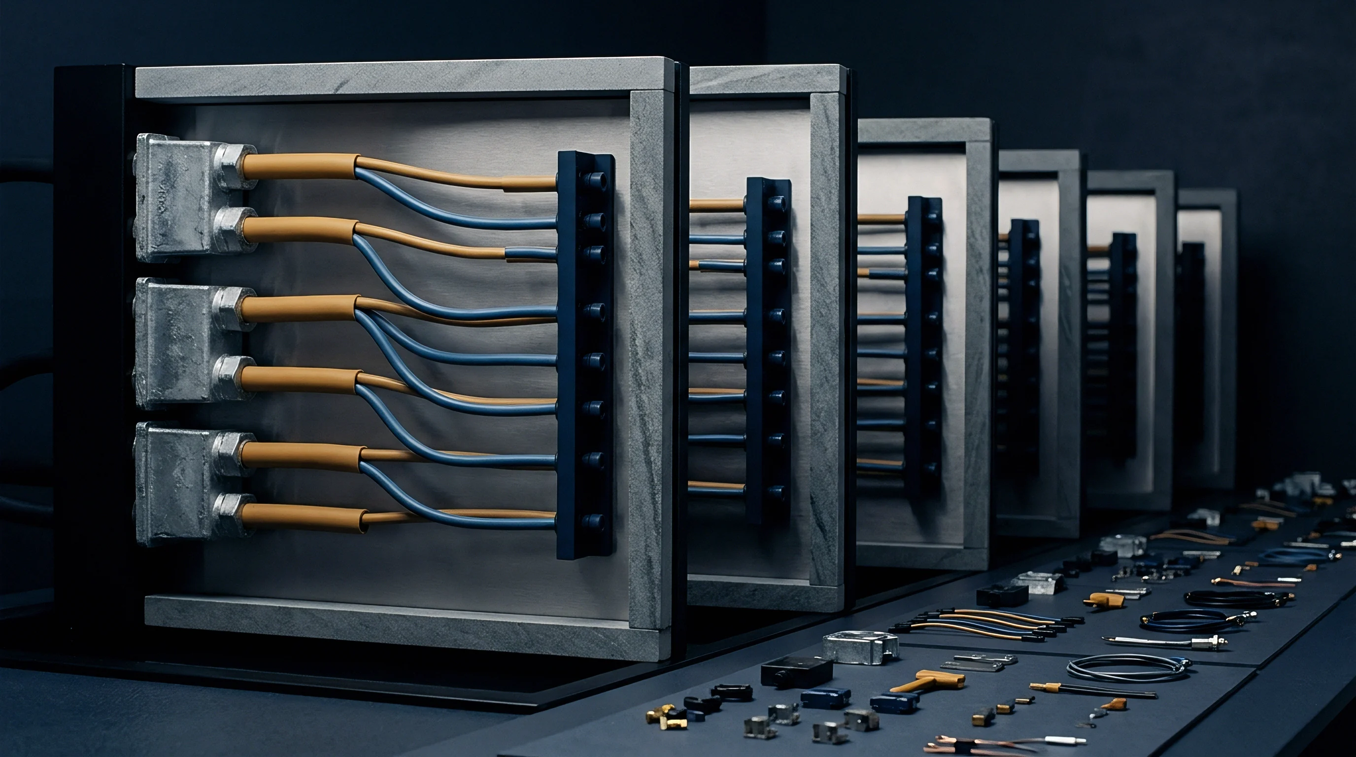
Capital Expenditure for Automated Vector Restraint Fixtures
Machined aluminum fixture bases, pneumatic actuators, and laser position sensors represent major up-front tooling investments. A dedicated multi-point vector cooling nest equipped with 12 pneumatic vector actuators, cooling air manifolds, and quick-change datum plates costs between 35,000 USD and 60,000 USD depending on automation level. Integrating robotic end-of-arm tooling adds secondary tooling expenses.
Buyers evaluate this capital expenditure against the press-hour savings achieved by shortening in-mold cooling times.

Cycle Time Amortization and Scrap Variance
Reducing press open time by transferring panel cooling to an offline vector fixture increases annual press throughput. Consider a production scenario running a 40 percent glass-filled polypropylene automotive tail-gate panel on a 1,500-tonne injection moulding machine. Assume an annual volume of 150,000 units over a five-year program life.
In Option A, the panel cools inside the injection mold for 45 seconds to achieve dimensional stability, resulting in a total press cycle time of 65 seconds. The machine operating cost is 120 USD per hour. At 65 seconds per part, the machine produces 55.38 parts per hour, yielding a press machine cost of 2.17 USD per panel.
In Option B, an offline dynamic multi-point vector cooling fixture is installed alongside an automated robot transfer arm. Tooling capital expenditure for the custom pneumatic vector fixture is 48,000 USD, with an additional 15,000 USD for robot end-of-arm tooling integration. In-mold cooling time drops from 45 seconds to 22 seconds because final dimensional stabilization occurs on the offline fixture while the press moulds the next part.
Total press cycle time decreases to 42 seconds.
At 42 seconds per part, press output increases to 85.71 parts per hour. The press machine cost per panel drops to 1.40 USD, saving 0.77 USD per part in press time. Across 150,000 parts per year, annual press operating savings total 115,500 USD.
Deducting the 63,000 USD total fixture capital expenditure, the offline multi-point vector system pays back fully in 6.5 months of production, generating 514,500 USD in net operating savings over the program life.
Investing in automated offline vector cooling hardware yields maximum financial return when production volumes exceed press capacity thresholds and raw material costs dominate part economics.