Injection Mould Cavity Surface Texture Replication Methods
Cavity surface texture replication depends on holding melt contact above glass transition temperature while peak packing pressure forces polymer into micro recesses.
Grain
How a cavity surface is prepared determines how accurately tool steel transfers micro-scale features into a finished polymer part. Toolmakers generate this micro-geometry using three main methods: chemical photo-etching, spark-erosion EDM texturing, or direct laser micro-ablation. Each leaves a distinct topographical signature on the steel wall, directly influencing melt flow, optical gloss, and demoulding friction.

Chemical Acid Etching Mechanics
Photolithographic masking shields select areas of the tool while acid dissolves unmasked steel to build geometric or random patterns. The process relies on repeated chemical attack, typically using ferric chloride or nitric-hydrochloric acid baths on tool steels like P20 (1.2311/1.2738) or H13 (1.2344). Reaction rates vary with alloy composition, heat treatment, and local grain orientation, so steel quality sets the foundation.
Matrix inhomogeneities like carbide segregation or localized hardness variation cause uneven etch depths across large surfaces. Photo-etching leaves rounded, isotropically distributed micro-peaks and valleys that yield a soft tactile feel. Typical etch depths run from 10 µm to 80 µm, though deeper patterns demand multiple masking and exposure cycles, raising both tooling costs and the risk of creating undercuts.

EDM Spark Erosion Texturing
Controlled electrical discharges between graphite or copper electrodes and hardened steel leave uniform arrays of micro-craters. High-frequency sparks under dielectric fluid melt and vaporize the steel surface, producing a non-directional, stochastic topography classified under VDI 3400 standards from VDI 12 (Ra 0.4 µm) to VDI 45 (Ra 18 µm). Intense thermal energy from the sparks creates a brittle recast layer rich in residual tensile stresses and micro-cracks.
Toolmakers must polish or chemically strip this white layer after texturing; otherwise, it risks premature mechanical fatigue and skin flaking during injection moulding cycles.
Laser Micro Ablation Technology
Five-axis optical systems focus pulsed laser beams to vaporize tool steel directly, eliminating chemical waste and electrode wear. Pulsed fiber lasers operating in nanosecond, picosecond, or femtosecond regimes ablate metal with depth precision down to 1 µm per pass. Because laser ablation maps digital CAD layouts straight onto the tool, it avoids the photo-mask alignment errors common on complex 3D freeform cavities.
Picosecond and femtosecond systems deliver pulses brief enough to prevent heat conduction into the surrounding metal, minimizing heat-affected zones and eliminating recast layers entirely. This allows for directional functional textures, biomimetic lotus patterns, and complex geometries that acid etching cannot match.
| Texturing Method | Standard Roughness Range (Ra, µm) | Feature Spatial Resolution (µm) | Steel Recast Layer Thickness (µm) | Cavity Cost Impact (USD per sq cm) |
|---|---|---|---|---|
| Chemical Photo-Etching | 0.8 to 12.5 | 50 to 100 | 0.0 | 12 to 35 |
| EDM Spark Erosion (VDI 12-45) | 0.4 to 18.0 | 20 to 150 | 2.0 to 15.0 | 8 to 22 |
| Nanosecond Laser Ablation | 0.2 to 25.0 | 10 to 30 | 1.0 to 4.0 | 25 to 60 |
| Femtosecond Laser Ablation | 0.05 to 15.0 | 1.0 to 5.0 | 0.0 | 45 to 110 |
Photo-etching handles deep ribs with minimal grain distortion, though manual touch-ups become necessary whenever acid breaches the masking tape.

Melt
Rheological behavior during cavity fill determines whether molten resin penetrates sub-micron features or bridges across the steel topography. To replicate fine detail, the melt stream must overcome fluid viscosity, surface tension, and rapid heat loss as it advances over cold tool surfaces. How completely the polymer fills these micro-cavities governs the visual appearance, feel, and friction of the finished part.

Frozen Skin Formation Dynamics
Thermal exchange between hot polymer and cool cavity walls creates a solidified boundary layer immediately upon contact. Thickness builds rapidly following heat conduction principles ~ proportional to the square root of thermal diffusivity multiplied by contact time. As this frozen skin forms, local resin viscosity spikes, resisting melt flow into fine surface valleys.
In standard cold-mould processing, the skin freezes before micro-features fill completely, leaving rounded texture peaks that lack the sharp fidelity of the original steel topography.
Peak packing pressure must reach the cavity surface before skin thickness exceeds fifteen percent of total wall section to prevent trapped micro-air.
Pressure Transmission across Micro Cavities
Hydrostatic force from the injection screw forces viscous fluid into sub-micron recesses before vitrification stops deformation. Local cavity pressure has to overcome both surface energy and the capillary resistance of trapped air inside micro-features. Raising melt temperature or injection speed enhances shear thinning, dropping resin viscosity according to the Cross-WLM rheological model and promoting flow into fine channels.
Excessive injection speed, however, can trap and compress air in closed texture pockets, causing micro-diesel burning and wearing away tool detail.

Variotherm Temperature Cycles
Dynamic cavity heating keeps tool steel above resin transition thresholds during injection, preventing early skin formation. Rapid Heat Cycle Molding (RHCM), or variotherm processing, uses steam, pressurized hot water, or conformal induction to heat cavity walls past the glass transition temperature (Tg) for amorphous resins or melting point (Tm) for semi-crystalline materials while filling. Maintaining tool temperature above Tg keeps the contact layer fluid, so moderate cavity pressures can drive melt into sub-micron features.
Once packing finishes, rapid coolant circulation drops tool temperature for safe ejection without unnecessarily dragging out cycle times.
| Polymer Grade | Mould Steel Temp (°C) | Cavity Packing Pressure (MPa) | Process Type | Replication Ratio (%) |
|---|---|---|---|---|
| ABS (General Purpose) | 50 | 40 | Standard Cold Mould | 62.4 |
| ABS (General Purpose) | 115 (Above Tg) | 40 | Variotherm Steam | 98.7 |
| PC (Optical Grade) | 85 | 60 | Standard Cold Mould | 54.1 |
| PC (Optical Grade) | 155 (Above Tg) | 60 | Variotherm Induction | 99.2 |
| PA66 (30% Glass Filled) | 80 | 70 | Standard Cold Mould | 48.3 |
| PA66 (30% Glass Filled) | 180 (Near Tm) | 70 | Variotherm Pressurized Water | 96.5 |
Running mould surfaces below the glass transition temperature forces cavity pressure to handle texture replication unassisted, elevating internal stress and warping parts.


Metrology
Topographical quantification translates physical surface structure into traceable metrics for engineering drawings. Traditional single-line profilometry cannot adequately capture complex 3D texturing. Evaluating replication accuracy instead requires spatial areal metrology and optical scattering measurements to map steel cavity geometry to the visual performance of the molded part.

Surface Roughness Metrics ISO 25178
Three-dimensional areal parameters replace traditional line scans to map height variations across textured surfaces. Standard 2D metrics like Ra (arithmetic mean deviation) and Rz (maximum profile height) miss critical information about spatial distribution. ISO 25178 addresses this with 3D areal metrics: Sa (arithmetic mean height), Sz (maximum height), Spd (peak density), and Sdr (developed interfacial area ratio).
Surface replication fidelity is expressed as the replication ratio Rf:
Rf = fracSa(moulded part)Sa(steel cavity) × 100
A replication ratio of 100 percent represents complete melt penetration to the floor of cavity valleys, while values below 80 percent signal severe skin bridging and rounded features.
Optical Profilometry Comparison
Non-contact interferometry and confocal scanning capture micro-cavity depths without deforming soft plastic or scratching polished inserts. Stylus tools drag a diamond tip that can plow through thermoplastic micro-peaks, generating artificially low height readings. Coherence Scanning Interferometry (CSI) and Laser Scanning Confocal Microscopy (LSCM) achieve sub-nanometer vertical resolution without touching the sample.
CSI works best on smooth micro-textures and polished tools, while LSCM handles steep sidewalls up to 75 degrees slope angle, making it well suited for inspecting deep grain undercuts on cavity steel.
Coherence scanning interferometry provides sub-nanometer vertical precision on optical tool inserts but loses signal coherence on cavity sidewalls exceeding sixty degrees inclination.
Gloss Variance and Micro Scattering
Reflectance measurements taken at standardized angles show how effectively micro-topography scatters light. Specular gloss measured per ISO 2813 or ASTM D523 at 20°, 60°, and 85° illumination serves as an indirect metric for texture transfer. Highly polished steel reflects light specularly, yielding high gloss units (GU).
As texture deepens or replication fidelity improves, micro-facets scatter incoming light diffusely, lowering gloss readings. Thermal or pressure variations across multi-cavity tools create localized gloss differences, causing visual cloudiness or splotching if Sa varies by as little as 0.15 µm across aesthetic surfaces.
ISO 21920 inspection standards stipulate that micro-texture compliance is judged on optical areal topography measured within seventy-two hours of ejection under controlled atmospheric conditions.

Draft
Demoulding geometry determines whether a textured part releases cleanly or scrapes against cavity sidewalls during ejection. Micro-textures create mechanical interlocks along tool surfaces. Without sufficient draft, ejection forces spike, causing scuffs, stress whitening, local deformation, or complete ejection binding.
Micro Mechanical Interlocking Mechanics
Polymer shrinkage generates mechanical resistance as the part begins to move. While shrinkage causes the moulding to pull away from cavity walls and grip core features tightly, micro-textures inside cavity recesses project perpendicular to the line of draw. Forcing plastic peaks past steel micro-ridges during ejection imposes high shear and compressive stress.
Clear friction during demoulding scales directly with resin elastic modulus, dynamic friction coefficient, and total vertical texture depth (Rz).

Draft Angle Calculation Rules
Draft angles must scale with pattern depth to ensure the part clears tool sidewalls as it moves. Untextured steel needs 0.5° to 1.0° of draft for clean release. Textured surfaces require extra taper calculated by a standard empirical rule: add 1.0° to 1.5° of draft for every 0.025 mm (25 µm) of texture depth.
A leatherette grain 100 µm deep, for example, requires at least 5.0° of draft per side. Inadequate taper forces ejector pins to push against severe friction, driving local stress past the polymer’s yield strength.
- Calculate maximum peak-to-valley texture depth Rz on cavity drawings using maximum manufacturing tolerances.
- Establish baseline polymer draft requirements based on resin shrink rate and elastic modulus.
- Add 1.25 degrees of draft per 25 micrometers of textured cavity depth to the baseline calculation.
- Relieve core sidewalls opposite heavy cavity textures to allow part deflection during initial ejection displacement.
- Verify ejector pin contact surface area to hold local compressive stress below fifty megapascals during part release.

Can Variotherm Mold Heating Eliminate Ejection Scuffing?
Thermal cycling alters how and when plastic shrinks, easing mechanical binding against cavity micro-grooves. Holding tool surface temperature near the polymer transition point during packing gives the material time for volumetric relaxation before the tool opens. When cooling water flushes through, the part skin cools evenly, backing plastic micro-peaks out of cavity undercuts before ejector pins move forward.
This reduction in scuffing allows engineers to trim required draft angles by 1.0° to 1.5° on tight enclosure designs.
Inadequate draft on deep leatherette finishes shears plastic micro-features, scores cavity walls, and halts automated moulding lines.


Economics
The true cost of textured tooling goes beyond initial machining quotes to encompass cycle time and ongoing tool maintenance. Choosing an advanced texturing process or dynamic thermal system affects both upfront CapEx and piece-price OpEx over the production lifespan. Sourcing strategies must weigh initial cavity processing fees against press-side cycle penalties and long-term refurbishment costs.
Tooling Amortisation and Initial Capital Expenditure
Capital costs for cavity engraving depend heavily on texturing method, steel hardness, and surface geometry. Chemical etching offers low entry costs for standard 2D textures, though custom patterns require photolithographic artwork setups that raise non-recurring engineering fees. EDM texturing adds minimal direct cost when using existing copper-tungsten electrodes, but electrode erosion forces multiple finishing passes.
Laser ablation carries a higher initial CapEx due to equipment depreciation, but it eliminates chemical mask consumables and hand polishing. On multi-cavity tools, laser texturing delivers identical digital replication across all cavities without the manual setup variation of photo-masking.
Laser cavity texturing increases initial tooling investment by twenty to forty percent compared to chemical etching but eliminates lot-to-lot visual variability across multi-cavity tools.
Cycle Time Penalties in Variotherm Processing
Rapid heating and active chilling extend cycle times, raising part costs on the press. Implementing variotherm processing to reach near-100 percent replication carries a direct thermal cycling penalty. Heating cavity steel from 60°C to 140°C with pressurized hot water or steam adds 4 to 12 seconds to the stroke, and subsequent cooling back to ejection temperature adds another 3 to 8 seconds.
On a cell running a 20-second baseline cycle, a 10-second variotherm addition increases press machine-hour costs by 50 percent.
| Texturing & Process Strategy | Relative Tooling Cost Factor | Cycle Time Penalty (sec) | Cavity Wear Resistance Index | Target Production Volume |
|---|---|---|---|---|
| Chemical Etching + Standard Cold Mould | 1.0x (Baseline) | 0.0 | Medium (Standard Steel) | 50,000 to 250,000 |
| Laser Ablation + Standard Cold Mould | 1.35x | 0.0 | High (Parent Metal Intact) | 100,000 to 1,000,000 |
| Chemical Etching + Steam Variotherm | 1.45x | +6.0 to +14.0 | Medium-Low (Thermal Shock) | 100,000 to 500,000 |
| Laser Ablation + Induction Variotherm | 1.80x | +2.5 to +6.0 | High (CrN/TiN Coated) | 500,000 to 3,000,000 |

Cavity Refurbishment and Wear Mechanics
Abrasive resins erode micro-peaks over long production runs, drifting part appearance out of spec. Molding glass-filled polymers like PA66-GF30 causes severe micro-plowing in high-velocity shear zones near sprues and gates. As cavity peaks wear flat, surface roughness decreases and part gloss rises over time.
Re-etching worn cavities requires stripping chemical nickel plating, acid-cleaning the steel, re-masking, and re-etching ~ a process that alters nominal cavity dimensions and tolerances under DIN 16742. Applying PVD coatings like Titanium Nitride (TiN) or Chromium Nitride (CrN) raises surface hardness above 2,000 HV, significantly extending texture life.
- Resin Abrasiveness Evaluation assesses filler types, glass fiber length, and particle hardness before setting target texturing depth.
- Tool Coating Selection applies PVD or diamond-like carbon coatings to protect micro-peaks against continuous shear erosion.
- Gate Location Optimization positions gates away from aesthetic show surfaces to avoid localized texture wash from melt jetting.
- Refurbishment Budget Allocations schedule chemical touch-ups or digital laser re-strikes every two hundred thousand cycles.
How long thin physical vapor deposition coatings can protect micron-scale laser structures against glass-fiber erosion before gloss drift forces full cavity re-machining remains unquantified across high-volume production runs.

Validation
Verification protocols ensure production mouldings match design specifications across every cavity position. Qualifying texture replication requires non-destructive optical inspection, gloss tracking, and statistical process control across shifts. Systematic validation isolates process-driven texture defects from toolmaking errors before final sign-off.

First Article Inspection Protocols
Initial off-tool samples are evaluated for geometry, surface reflectance, and feel against approved boundary masters. First article inspection (FAI) requires measuring Sa and gloss at designated points across the part, including gate regions, end-of-fill zones, and deep ribs. Gloss variations exceeding 1.5 GU between the gate and end-of-fill indicate localized pressure drops or premature skin freezing.
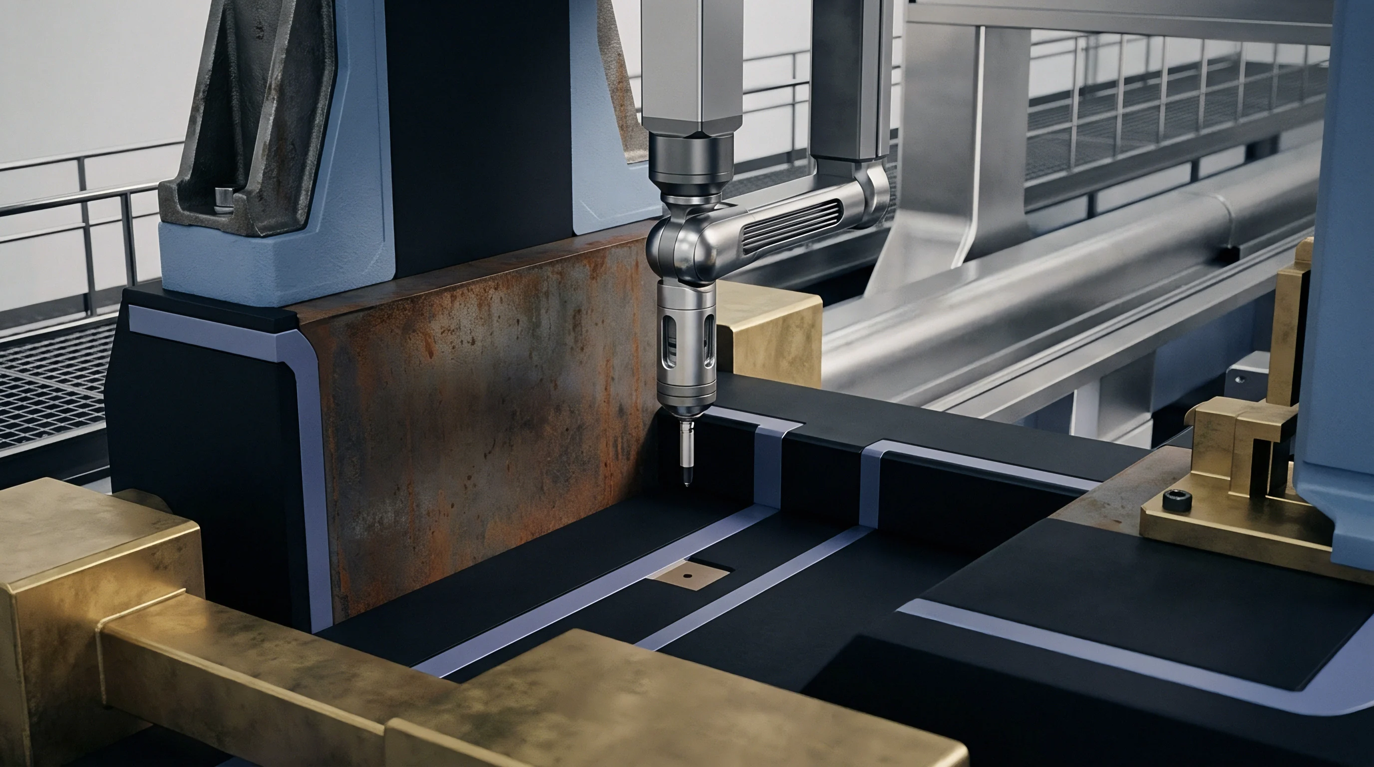
Engineering teams audit T1 samples with optical profilometry to map actual replication percentages against CAD baseline textures.
Resin Viscosity Drift Management
Melt flow variations between resin lots alter cavity pressure distribution, directly affecting micro-feature depth consistency. Material suppliers guarantee melt flow rate (MFR) within tolerance bands that often span ±15 percent under ISO 1133. A resin batch at the high-viscosity (low MFR) limit increases resistance to micro-cavity fill, reducing replication depth unless technicians adjust packing pressure or barrel temperatures.
Cavity pressure transducers with closed-loop feedback maintain peak packing pressure, compensating for batch-to-batch viscosity shifts during automated runs.

Production Quality Audit Boundaries
Statistical process monitoring tracks reflectance across shifts to catch texture degradation before parts fail inspection. Inline 60-degree gloss meters mounted on robot arms sweep show surfaces immediately after part removal. Plotting gloss readings on control charts reveals tool wear, vent contamination, or oil fouling before non-conforming lots reach assembly.
- Micro Diesel Venting Burn occurs when air trapped inside micro-texture pockets ignites under severe compression, charring polymer tips and eroding steel.
- Gloss Splotchiness Defect develops when uneven mold temperatures cause localized skin freezing variations across aesthetic panels.
- Texture Scuff Whitening manifests as light streaks on sidewalls when plastic micro-peaks shear off during ejector stroke.
- Erosion Gloss Drift appears gradually over extended runs as glass fibers round off cavity micro-peaks, elevating surface gloss.
Establishing clear boundary samples for visual reflectance and tactile feel alongside optical profilometry limits guarantees consistent texture quality throughout production runs. Matching first-article surface topography against the production baseline prevents lot rejections and locks down process capability before commercial tool release.