Tool Steel Waveguide Channel Micro-Machining Surface Topography Optimization
Optimizing tool steel grain homogeny and micro-milling shear kinematics yields sub-100nm Sa channel surfaces, preventing mmWave signal attenuation.


Grain

Carbide Distribution Impact on Micro Cutting Flank Wear
Microstructure uniformity within hardened tool steels establishes the physical boundary for micro-machining floor quality and edge fidelity. When micro-endmills with cutting radii ranging from 5 to 15 micrometers cut sub-millimeter channel structures, individual metal carbide inclusions within the steel matrix act as discrete structural obstacles. Standard AISI H13 or conventional 420 stainless steel grades contain primary chromium carbides exceeding 3 micrometers in cross-section.
These large inclusions induce severe mechanical shock loads on ultrafine tool flutes, driving micro-chipping on cutter margins and leaving irregular void networks along the milled channel floor.
Electroslag remelted and powder metallurgy steel formulations eliminate these macroscopic carbide clusters. Grades such as Stavax ESR, Böhler M333, or CPM 15V present a refined, highly homogenous martensitic structure with primary carbides held under 0.5 micrometers. This metallurgical structure prevents localized tool chatter and surface pitting during micro-milling passes.
Tool steel selection governs micro-machining limits. Sub-surface micro-pitting directly damages the electrical skin depth layer of high-frequency waveguides, causing localized phase distortion and parasitic signal scattering.
Triple-melted stainless steel grades prevent microscopic surface pullout where high-frequency skin depth limits tolerance boundaries.
Structural integrity depends on heat treatment protocols that minimize residual stress while maintaining a matrix hardness between 52 and 56 HRC. Lower hardness values invite material ploughing and burr formation along channel borders. Hardness levels above 58 HRC accelerate brittle micro-fracturing of tungsten carbide tool edges.
Vacuum heat treatment combined with cryogenic freezing cycles stabilizes retained austenite, preventing dimensional drift in micro-moulded channel inserts over high-volume production cycles.
- Primary Carbide Pullout Cavities remain where hard metal carbides detach from the softer martensitic matrix during micro-milling, leaving pits exceeding 0.8 micrometers in depth along the waveguide signal path.
- Subsurface Lattice Micro-Cracking Mechanical stress concentrations around localized carbide clusters induce microscopic fracture networks during single-point diamond or carbide pass sequences.
- Micro-Flank Edge Chipping Cutting edge radii under 15 micrometers collapse prematurely upon entering high-hardness inclusions within standard tool steel billets.
Material suppliers frequently assert that micro-pitting within acceptable hardness tolerances falls within normal mill material variances rather than raw material defects.


Pass
How Does Spindle Speed Dictate Micro Channel Surface Topography?
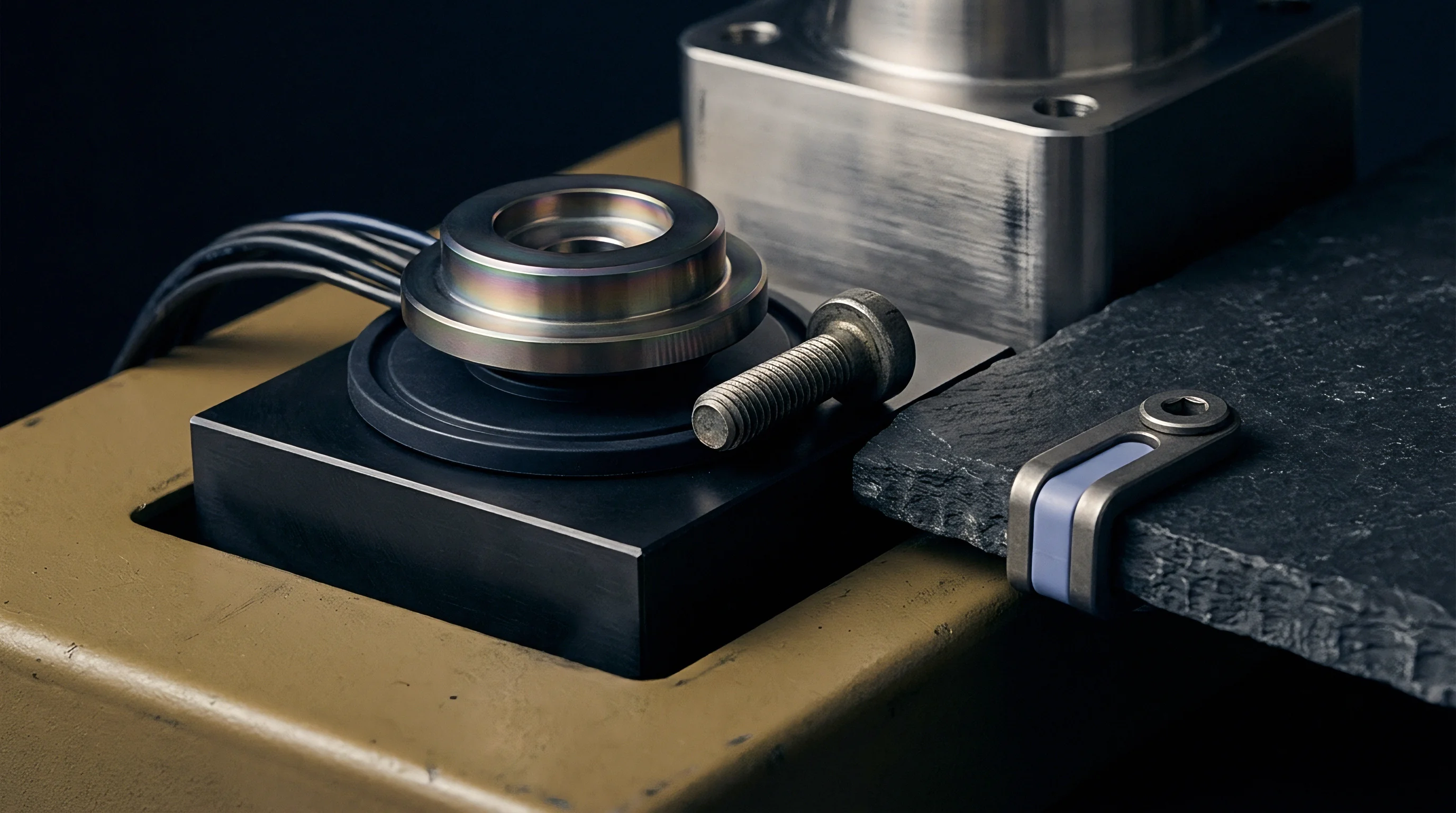
Precision micro-endmilling relies on maintaining stable shear deformation within extremely small engagement zones. Radial depth of cut, axial depth of cut, and feed per tooth dictate whether a cutter cleanly shears steel or plastically deforms the matrix through material ploughing. When chip load drops below the cutting edge radius, tool edges compress and burnish the steel substrate rather than forming true chips.
This burnishing action generates high local friction, micro-welding, and periodic surface ripples along waveguide channel sidewalls.
Spindle speeds between 60,000 and 100,000 RPM are mandatory to achieve efficient cutting velocities with micro-tools under 0.5 millimeters in diameter. Air-bearing spindles eliminate mechanical vibration and hold dynamic runout under 0.5 micrometers. Dynamic runout exceeding ten percent of the target feed per tooth causes asymmetric tool loading, driving total wave form errors along channel surfaces and leading to premature cutter fracture.
Shear deformation replaces material ploughing. Spindle dynamic runout destroys micro-tool flutes.
- Clean the precision air-bearing spindle taper with isopropyl alcohol and verify static runout remains under 0.5 micrometers using a capacitive displacement probe.
- Mount the ultrafine-grained carbide tool using micro-shrink fit holders and establish dynamic tool length offsets at operating rotational velocities.
- Execute roughing routines leaving a constant 10 micrometer stock allowance across all waveguide channel sidewalls and floor surfaces.
- Perform finish micro-milling sweeps utilizing feed per tooth parameters that exceed the effective cutting edge radius by twenty percent.
Finish machining strategy demands continuous stepover control to limit residual cusp height. Ball-nose and torus micro-cutters require tight axial and radial stepover settings, typically between two and eight percent of the effective tool diameter, to deliver sub-100 nanometer surface finishes on concave or floor features.
| Tool Steel Grade | Hardness (HRC) | Spindle Speed (RPM) | Feed per Tooth (µm/tooth) | Axial Depth ap (µm) | Achievable Roughness Sa (nm) |
|---|---|---|---|---|---|
| Stavax ESR | 52–54 | 80,000 | 0.8–1.2 | 5–10 | 45–65 |
| Böhler M333 | 54–56 | 90,000 | 0.5–1.0 | 4–8 | 30–50 |
| AISI H13 (ESR) | 48–52 | 60,000 | 1.0–2.0 | 10–15 | 85–120 |
| NAK80 | 38–42 | 60,000 | 1.5–2.5 | 15–20 | 110–160 |
A feed per tooth below one micrometer increases surface roughness by forty percent when cutting edge radius exceeds two micrometers.
How thermal expansion of ultra-high-speed spindles across continuous ten-hour machining runs affects profile height consistency along sixty-gigahertz waveguide channels remains an open engineering problem.


Ablation

Non Contact Photon Processing Boundaries
Ultrashort pulse laser machining offers a non-mechanical alternative for structuring tool steel inserts without inducing cutter tool deflection or edge wear. Femtosecond laser sources operating with pulse durations under 500 femtoseconds transfer energy into the steel lattice faster than thermal diffusion occurs. Steel transforms directly from solid to vapor, eliminating the macro Heat-Affected Zone (HAZ) and recast layers characteristic of nanosecond lasers or micro-EDM processes.
Laser pulses vaporize steel without melting.
Micro-EDM (Electro-Discharge Machining) provides deep trench cutting capabilities but leaves a distinct surface topography composed of overlapping discharge craters. These craters create high spatial frequency noise along waveguide surfaces. The melted re-solidified layer contains micro-cracks and tensile residual stresses that reduce tool insert fatigue strength under repeated injection molding clamp pressure cycles.
| Process Type | Minimum Feature Radius (µm) | Floor Roughness Sa (nm) | Recast Layer Thickness (µm) | Machining Rate (mm³/min) |
|---|---|---|---|---|
| Mechanical Micro-Milling | 15 | 30–60 | 0.0 | 0.12–0.45 |
| Femtosecond Laser Ablation | 5 | 80–150 | < 0.1 | 0.05–0.20 |
| Sink Micro-EDM | 10 | 180–350 | 1.5–4.0 | 0.08–0.30 |
Femtosecond laser processing generates periodic surface structures known as ripples or LIPSS (Laser-Induced Periodic Surface Structures). While these sub-micron ripples can be oriented parallel to the high-frequency current vector to minimize attenuation, they introduce anisotropic surface properties that complicate plastic part release during injection molding. Surface finish dictates high-frequency wave loss.
Selecting thermal pulse regimes above two picoseconds creates a recast layer that exfoliates during high-pressure polymer injection, destroying waveguide channel geometry and forcing immediate insert replacement.

Topography
Surface Metrology Metrics for High Frequency Signal Integrity
Characterizing micro-machined tool steel inserts requires moving beyond conventional two-dimensional line profiles (Ra, Rz) to three-dimensional areal surface parameters defined under ISO 25178. Two-dimensional profile measurements fail to capture spatial lay, isolated pits, or directional lay patterns produced by micro-milling paths. In high-frequency electromagnetic applications, signal current flows within a thin outer layer defined by the skin depth, which decreases as operating frequency rises.
At 110 GHz (D-band), the skin depth in copper or aluminum molded waveguides drops below 200 nanometers. If the areal root mean square surface height (Sq) or arithmetic mean height (Sa) approaches or exceeds the skin depth, the effective path length for electrical conduction increases, inducing significant attenuation losses. Spatial frequency content matters equally: surface lay perpendicular to current flow creates significantly higher conductor loss than lay parallel to propagation.
Skin depth limits current transport layer. Rough surfaces increase high-frequency attenuation. Metrology verifies channel floor roughness.
- Coherence Scanning Interferometry Selection Non-contact optical profiling prevents stylus scratching on polished channel walls while maintaining 0.1 nanometer vertical resolution.
- Spatial Gaussian Filter Cutoff Calibration S-filter and L-filter spatial cutoff settings isolate machine vibration marks from intrinsic material grain roughness.
- Areal Roughness Parameter Extraction Arithmetic mean height Sa provides surface volume baseline while texture aspect ratio Str confirms machining directional lay.
Non-contact coherence scanning interferometry (CSI) or confocal optical microscopy provides the spatial resolution necessary to map sub-millimeter waveguide channels without damaging delicate channel corners. Measurement instruments must isolate high-frequency surface roughness from low-frequency form error. Applying proper spatial Gaussian filters ensures that tool runout, machine guidance errors, and intrinsic material roughness are evaluated independently.
ISO 25178-2 specifies spatial filtration limits that prevent instrument noise from distorting optical surface roughness reporting.
Contract clauses specifying ISO 21920 surface texture conformance require explicit reporting of filter bandwidth thresholds, without which compliance audits remain legally void.


Yield

Insert Life Cycle Economics and Attenuation Degradation
Tool steel micro-machining parameters directly govern insert cost, production lifecycle, and replication fidelity during micro-injection molding. High-frequency polymer waveguides molded from unfilled cyclic olefin polymers (COP) or liquid crystal polymers (LCP) replicate tool surface features down to sub-50 nanometer scales. Polymer melt flow under high injection pressures (1200–1800 bar) causes progressive micro-abrasion along mold steel surfaces over long production shifts.
Tool wear alters sidewall surface lay. Insert replacement resets surface finish quality. Tooling costs impact unit part economics.
Polymer flow erodes polished channel walls.
Abrasive wear degrades polished floor finishes, increasing wall surface roughness over time. In high-frequency applications, an increase in tool Sa from 40 nanometers to 150 nanometers elevates signal attenuation across molded parts by up to 1.8 dB per centimeter at 140 GHz. Tool insert replacement schedules must be tied directly to allowable RF attenuation thresholds rather than catastrophic mechanical tool failure.
| Injection Shot Count | Tool Floor Sa (nm) | Molded Part Sa (nm) | 140 GHz Attenuation (dB/cm) | Replication Fidelity (%) |
|---|---|---|---|---|
| 1 | 35 | 38 | 0.42 | 92.1 |
| 10,000 | 42 | 46 | 0.48 | 91.3 |
| 25,000 | 68 | 72 | 0.75 | 94.4 |
| 50,000 | 125 | 130 | 1.35 | 96.1 |
| 75,000 | 210 | 218 | 2.10 | 96.3 |
| Data measured using Stavax ESR insert (54 HRC) molding Cyclic Olefin Polymer (COP) at 290°C melt temperature and 1400 bar packing pressure. | ||||
Abrasive polymer flow degrades micro-channel wall finishes far faster than mechanical mold clamping cycles.
Mold insert replacement intervals for sub-millimeter waveguide channels balance initial micro-machining toolroom costs against allowable signal loss drift in end-use mmWave transceivers.