Establishing Cavity Pressure Thresholds to Compensate Non Uniform Viscous Heating across High Cavitation Tooling
Calibrating cavity pressure switchover thresholds eliminates part mass variance caused by runner shear heating across high cavitation tooling.
Friction
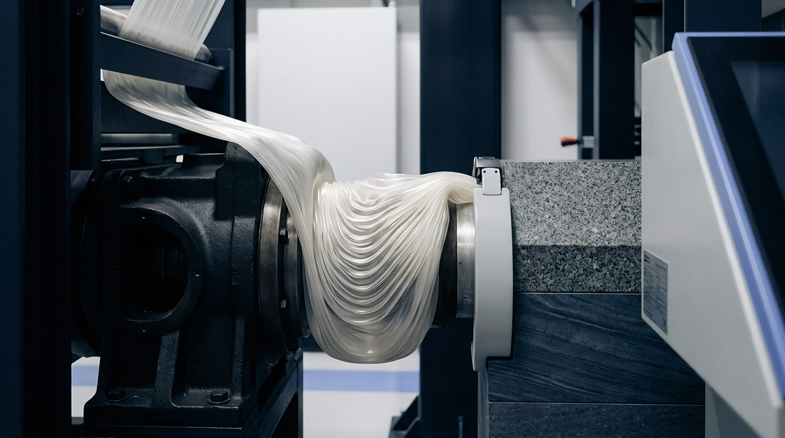
Melt traveling through high-cavitation delivery systems experiences intense localized shear rates along channel walls. Viscous dissipation transforms mechanical drive energy from the injection screw into thermal energy within the polymer boundary layer. In manifold configurations feeding thirty-two, sixty-four, or one hundred twenty-eight impressions, this localized heating alters the fluid condition before resin reaches the gate.
Shear heats the channel walls. Viscosity drops along hot boundaries. The core of the melt stream remains cooler, creating thermal laminations that split unevenly at runner junctions.
Calculations using the Carreau-Yasuda model reveal severe viscosity declines near channel perimeters. When molten resin navigates a ninety-degree turn at a runner intersection, the sheared, low-viscosity outer skin preferentially turns into one side of downstream sub-runners. Inner cavities receive melt that has absorbed multiple viscous dissipation events, while outer cavities receive melt containing cooler core material.
The resulting melt temperature spread across impressions often spans 12°C to 24°C in uncorrected manifold geometries.
A geometrically balanced runner layout generates an unbalanced thermal profile across cavitation counts above sixteen.
Thermographic probing at parting surfaces reveals severe thermal gradients between center and edge impressions. The temperature delta produces immediate consequences in cavity filling speed. Fluid entering hotter cavities encounters lower flow resistance, advancing rapidly under constant machine flow rates.
Cooler cavities display sluggish fill fronts, leading to asymmetric volumetric filling despite identical steel runner diameters. Non-uniform heating alters gate freeze timing, packing pressure transmission, and ultimate part shrinkage.
| Resin Grade | Nominal Melt Temp (°C) | Wall Shear Rate (1/s) | Primary Runner Delta (°C) | Tertiary Runner Delta (°C) | Net Viscosity Shift (%) |
|---|---|---|---|---|---|
| Polypropylene (MFI 25) | 220 | 14,500 | +4.2 | +13.8 | -28.4 |
| Polyoxymethylene (MFI 9) | 205 | 18,200 | +6.1 | +21.4 | -39.1 |
| Polycarbonate (MFI 10) | 295 | 11,300 | +5.8 | +17.6 | -34.6 |
| Polyamide 66 (30% Glass) | 285 | 22,000 | +8.4 | +24.7 | -44.2 |
Thermal gradients originate from predictable geometric features within the melt delivery tract.
- Manifold Runner Junctions induce severe velocity profile skewing as laminar boundaries divide across successive branch intersections.
- Wall Proximity Velocity Peaks generate steep velocity gradients that concentrate viscous dissipation within a 0.2 millimeter skin layer.
- Gate Choke Restrictions impart extreme final shear acceleration immediately prior to cavity entry, elevating local melt temperatures.
- Sub-Runner Diameter Steps alter the local Reynolds number and shear stress, compounding thermal divergence across cavitation clusters.
The toolmaker routinely attributes cavity weight variation to runner plate thermal expansion, avoiding discussion of shear heating within sub-runners.


Sensor
Piezoelectric quartz transducers convert mechanical cavity deflection into picocoulomb charge packets during the injection phase. These instruments monitor the real physical state of the polymer inside the impression, circumventing machine-level signal distortion. Hydraulic pressure readings at the injection cylinder reflect total system friction, including check-ring slippage, barrel drag, and runner resistance.
Quartz crystals output linear charge. Direct flush diaphragms capture true melt contact without mechanical drag. Indirect installations employ ejector pins resting on button load cells to measure cavity force through steel transmission.
Direct transducers mount flush with the cavity wall, providing immediate response times necessary for recording high-speed fill transients. Indirect transducers place the sensing face behind an ejector pin, lowering tooling modification expenses while introducing mechanical noise. Ejector pin clearance tolerances permit polymer dust accumulation, dampening force transmission over thousands of cycles.
Side friction skews indirect pins.
At 1200 bar cavity pressure, an indirect pin loses up to twelve percent of its transmitted force to sidewall contact inside the guide hole.
Toolmaker bench records establish that quartz transducers maintain 0.5 percent linearity up to 2000 bar under 200°C operating temperatures, a rating validated on fifty sensor units tested under cyclic hydraulic loading in 2023, though mechanical pin binding invalidates this tolerance.
| Transducer Type | Direct Diaphragm | Indirect Ejector Pin | Runner Block Sensor |
|---|---|---|---|
| Response Time | < 1.0 ms | 4.0 to 8.0 ms | < 2.0 ms |
| Measurement Accuracy | ± 1.0% Full Scale | ± 4.5% Full Scale | ± 2.5% Full Scale |
| Tooling Machining Cost | $1,200 per cavity | $450 per cavity | $600 per runner drop |
| Maintenance Frequency | 1,000,000 cycles | 250,000 cycles | 500,000 cycles |
| Failure Mode | Abrasive face wear | Pin seizure and binding | Cable thermal fatigue |
Will Shear Dissipation Shift Gate Freezing Time?
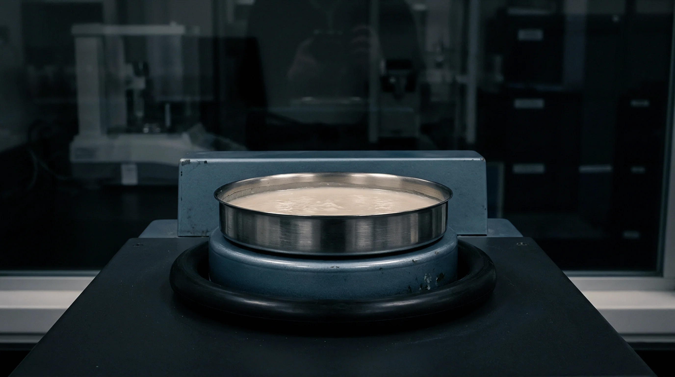
Thermal splits across delivery channels alter the solidification rate within individual cavity entry orifices. When viscous heating raises melt temperatures in specific runner branches by 15°C, the corresponding gate requires extended packing time to freeze completely. Press operators using screw stroke transfer cut off pressure transmission while hotter gates remain open.
Polymer flows backward from hot cavities into the runner system if holding pressure drops before the gate seals. Gate freeze halts cavity packing. Cold cavities freeze early, trapping mass inside the cavity under high residual pressure, while hot cavities experience gate discharge, yielding sink marks and short shots.
Locate the transducer opposite the thinnest rib when short shots dictate the scrap boundary.

Threshold
Process stabilization across sixty-four cavities rests on locking transfer points to real melt front arrival. Screw displacement fails when melt viscosity shifts. Modern press controllers transition from speed control to pressure hold using a cavity pressure threshold signal.
In high-cavitation tooling subject to viscous dissipation, a single cavity sensor cannot represent the complete mould state. Sentinel cavities chosen from the hottest and coldest runner positions provide boundary limits for the entire tool.
Setting the switchover threshold requires evaluating both peak cavity pressure and the pressure-time curve area. Peak pressure governs mold parting. Pressure impulse dictates part mass.
When the primary control cavity hits its preset threshold, the press drops velocity and enters pack phase, dampening the pressure surge in early-filling cavities.
Sentinel transducers placed on opposite thermal extremes provide sufficient control without the expense of individual channel cabling.
Screw position transfer ignores fluid viscosity. Setting limits across sixty-four impressions demands a defined calibration sequence.
- Establishing Peak Pressure Limits fixes boundary conditions preventing parting line separation during peak shear spikes.
- Calculating Pressure-Time Integrals locks volumetric shrinkage across cavities running disparate thermal histories.
- Configuring Cavity Switchover Triggers transfers the press from velocity to pressure control before the fastest cavity packs rigid.
- Mapping Automated Part Rejection isolates components from cavities whose fill curves drift outside three standard deviations.
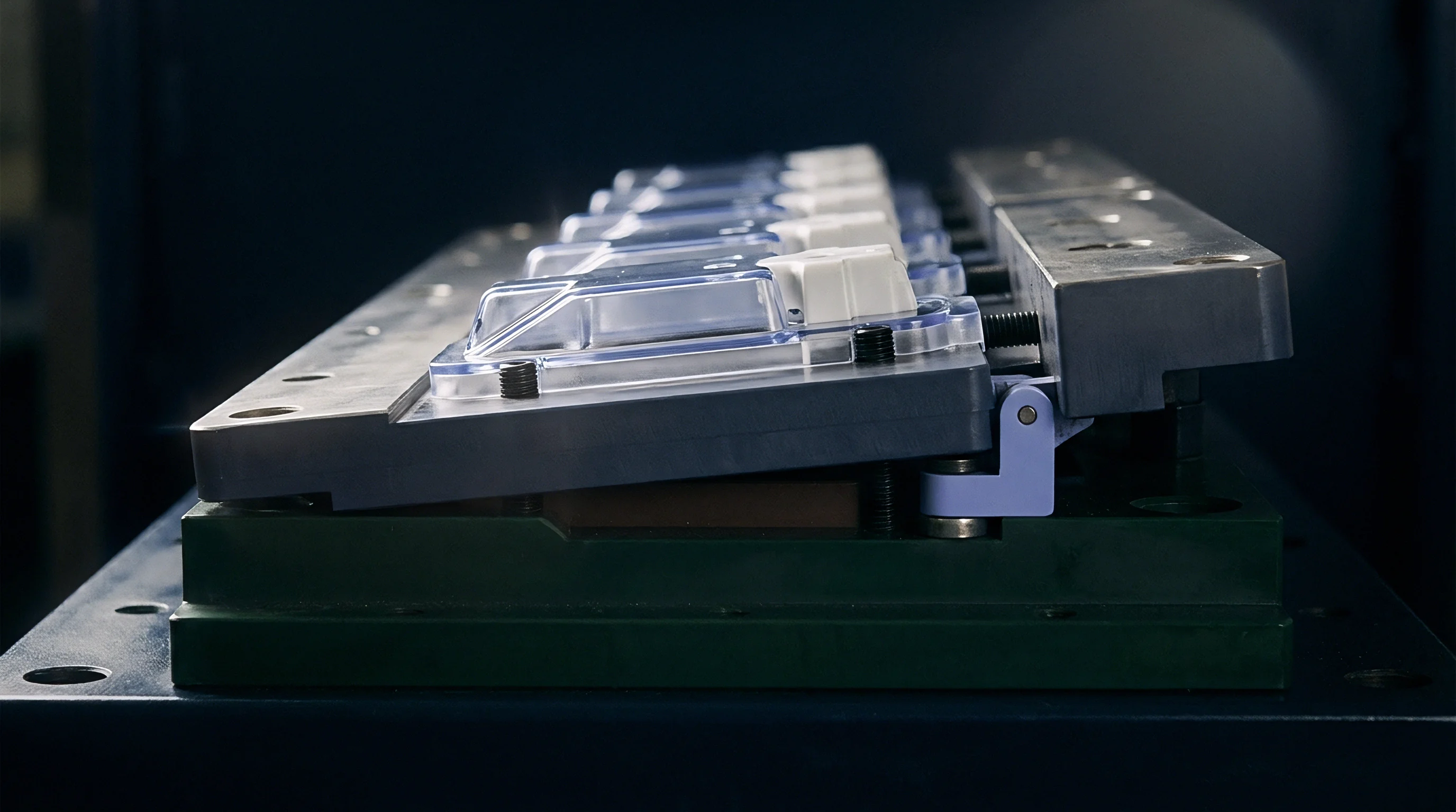
Could Active Cutoffs Prevent Mold Flash?
Holding force limits generate parting separation when resin temperatures rise in interior tooling locations. Low-viscosity resin pressurized above the clamp capability forces mould halves apart by several microns, creating flash across part perimeters. Active cavity pressure thresholds monitor the rate of pressure rise during the final five percent of cavity fill.
When the transducer detects a pressure rise rate exceeding 250 bar per hundredth of a second, the press controller immediately clamps hold pressure, preventing hydrostatic tool opening.
Triggering transfer from an unheated runner stream drives hot cavities into over-packing, causing tool parting separation and parting line burrs.
Variance
Disparities in thermal history between inner and outer cavities alter the specific volume trajectories of semi-crystalline polymers. Polypropylene and polyoxymethylene contract sharply as polymer chains align during crystalline phase transformation. Higher melt temperatures delay crystallization, allowing packing pressure to feed additional mass into the part volume for an extended duration.
Cooler cavities freeze prematurely. Hotter cavities pack longer. The resulting component weight distribution displays clustering that maps directly to the runner layout.
Published injection trials on polyoxymethylene across a 64-cavity medical tool in 2022 documented a 14.2 bar-second pressure impulse variation for every 5°C shift in runner melt temperature, based on thirty consecutive shots; this relationship holds only when cooling water maintains turbulent flow with a Reynolds number exceeding 4000.
High-speed rail axle bearings display identical boundary layer heating when lubricant channels experience intense localized wall shear. In polymer processing, the fluid freezes within seconds, locking residual stress into the finished component. Melt compressibility alters volume calculations.
Shrinkage differentials induce part warp. Unbalanced heating skews mechanical tolerances.
Tolerance group 130 under DIN 16742 permits plus or minus 0.04 millimeters on an eight-millimeter bore, which fails immediately when cavity pressure curve areas diverge beyond six percent.
| Parameter | Machine Stroke Control | Single Cavity Switchover | Dual Sentinel Threshold | Tolerance Target (DIN 16742) |
|---|---|---|---|---|
| Mean Part Mass (g) | 2.45 | 2.48 | 2.47 | 2.46 ± 0.03 |
| Mass Spread Range (g) | 0.14 | 0.08 | 0.03 | 0.06 Max |
| Outer Diameter (mm) | 12.08 | 12.04 | 12.01 | 12.00 ± 0.04 |
| Diameter Spread (mm) | 0.11 | 0.07 | 0.03 | 0.04 Max |
| Process Capability (Cpk) | 0.72 | 1.08 | 1.54 | > 1.33 Required |
| Data recorded over 500 consecutive production cycles using polyoxymethylene copolymer under 80-tonne clamp force. | ||||
Correcting runner geometry redistributes the sheared boundary layers before the fluid reaches secondary splits. Melt flipper inserts rotate the laminar flow profile ninety degrees at runner junctions, transposing the hot boundary layer into the core of the downstream branch. Combining melt rotation hardware with cavity pressure monitoring eliminates dimensional drift across distant impressions.
- Cavity Transducer Allocation determines whether to instrument all impressions or place sentinel units on extreme thermal branches.
- Manifold Melt Rotation installs specialized runner inserts to physically reposition high-shear boundary layers into the sub-runner core.
- Independent Cavity Valving installs pneumatically actuated valve pins to shut off individual gates upon reaching threshold pressure.
- Post-Mold Annealing Budgets accounts for secondary stress relaxation when differential shrinkage exceeds drawing limits.
Tool designers still dispute whether individual cavity shut-off pins can eliminate dimensional variance across high-cavitation moulds processing polycondensates without requiring downstream mass classification.
Settlement
Instrumentation capital for high-cavitation tooling directly alters both the initial build quotation and the subsequent cost per shot. Outfitting sixty-four impressions with quartz transducers adds significant initial equipment expense. A complete installation encompassing sixty-four direct pressure transducers, multi-channel charge amplifiers, specialized wiring harnesses, and press controller software interfaces adds between $45,000 and $70,000 to the tooling invoice.
Uninstrumented tools conceal cavity divergence. Instrumentation raises initial capital cost. Tool qualification demands cycle proof.
Scrap reductions yield rapid payback. Consider an automated sixty-four cavity tool cycling at 6.5 seconds, running 5,000 hours annually, producing 177 million parts. A baseline reject rate of 3.2 percent stemming from dimensional drift in high-shear cavities discards 5.6 million parts per year.
At a piece manufacturing price of $0.035, annual scrap losses total $198,000. Implementing sentinel cavity pressure threshold controls cuts the scrap rate below 0.6 percent. The tooling instrumentation package pays for itself within five months of continuous operation.
Moulders report an average scrap reduction of 4.2 percent after implementing cavity pressure switchover on balanced 64-cavity tools, yet plant-level variations in regrind proportion and ambient warehouse temperatures prevent rigorous verification of this exact figure.
| Cost Component | Standard Machine Stroke | Four Sentinel Sensors | Full 64-Cavity Instrumentation |
|---|---|---|---|
| Initial Tooling Surcharge | $0 | $8,500 | $58,000 |
| Annual Maintenance Cost | $1,200 | $2,400 | $12,500 |
| Scrap Rate Across Run (%) | 3.4% | 0.9% | 0.4% |
| Annual Scrap Value Discarded | $210,000 | $55,000 | $24,000 |
| Net Annualized Savings | Baseline | $146,100 | $139,500 |
Standard tooling acceptance clause 7.3 binds tool release to capability indexes exceeding 1.33 across all individual impressions at quotation cycle speed, transferring reworking expenses to the mould builder.