Polymer Melt Flow Behavior in High Shear Injection Molds
High shear molding relies on pseudoplastic shear thinning, requiring capillary rheometry over melt flow index to control viscous heating and pressure losses.


Gradient
Injection molding thin-wall packaging, electronic enclosures, and micro-fluidic connectors drives polymer melt velocities through constricted pin gates and sub-millimeter cavities where shear rates range between 10,000 s^-1 and 100,000 s^-1. Under these extreme velocity gradients, macromolecular chains uncoil from their random coil equilibrium state and align parallel to the direction of flow. This structural orientation reduces dynamic entanglements per unit volume, causing the apparent melt viscosity to drop by up to three orders of magnitude compared to zero-shear conditions.
Analyzing non-Newtonian flow behavior at extreme velocity gradients requires non-linear mathematical models because simple power-law equations fail near lower and upper Newtonian plateaus. The Cross-WMM model expresses apparent viscosity as a function of shear rate, temperature, and pressure, capturing the transition from the zero-shear plateau to the power-law shear-thinning regime:
η(γ̇, T, P) = η₀(T, P) /
In this expression, η₀ represents zero-shear viscosity, τ defines the critical shear stress level at which the material transitions into shear thinning, and n represents the power-law index. Resins with lower power-law indices exhibit aggressive shear thinning, enabling molders to fill ultra-thin sections without exceeding machine pressure limits. However, relying on extreme velocity gradients to drive material into remote cavity corners introduces severe processing risks when tool velocities fluctuate during transfer from pressure-controlled injection to pack-and-hold phases.
A melt temperature increase of 38 °C occurs inside a 0.8 mm pin gate when injection velocity exceeds 350 mm/s under a gate shear rate of 82,000 s^-1.
Tooling design for high-shear molding demands precise gate positioning and cross-sectional sizing to prevent flow instabilities. When melt encounters sudden area reductions at gate entries, the localized velocity gradient increases exponentially, establishing high shear stress zones along channel walls while central core regions move at near-plug velocities. This steep shear rate profile induces distinct molecular orientation bands across the wall-to-core thickness.
- Hesitation Marks ~ Mold cavity wall freezing during high-shear fill transitions when velocity gradients drop abruptly below critical thresholds.
- Gate Burn Marks ~ Extreme localized frictional heating resulting in resin thermal scission and surface discoloration near restricted runner entry points.
- Cavity Pressure Spikes ~ Sudden resistance rises occurring when pseudo-plastic shear thinning plateaus near the second Newtonian region under ultra-high velocity gradients.
| Grade Family | Test Temp (°C) | Zero-Shear Viscosity (Pa·s) | Power-Law Index n | Critical Shear Stress (kPa) |
|---|---|---|---|---|
| 230 | 420 | 0.31 | 22.4 | |
| 300 | 680 | 0.68 | 48.1 | |
| 285 | 180 | 0.52 | 15.8 | |
| 340 | 95 | 0.18 | 8.2 |
Underestimating the transition point between power-law thinning and second Newtonian behavior leads to miscalculated injection pressure requirements, causing unexpected mold hesitation, short shots, and flash along parting lines.

Dissipation
Mechanical energy expended by the injection unit hydraulic or electric drive system converts directly into thermal energy as polymer chains slide past one another under high shear stress. This process, known as viscous dissipation or shear heating, elevates the bulk melt temperature within localized flow channels beyond the setpoints maintained by barrel heating bands. In runner systems and micro-gates operating above 20,000 s^-1, viscous dissipation generates volumetric heat faster than the tool metal can conduct it away, creating thermal core spikes that alter polymer degradation kinetics.
The volumetric rate of heat generation from viscous dissipation relates directly to melt viscosity and the square of the local shear rate:
q̇_v = η γ̇^2
Because shear rate peaks near the boundary wall while melt viscosity decreases with elevated temperature, maximum heat generation occurs in a narrow layer adjacent to the solid frozen skin. In high-speed injection operations using multi-cavity tools, temperature spikes of 20 °C to 50 °C routinely develop within restricted gate lands. This localized thermal expansion alters part density profiles, increases volumetric shrinkage, and degrades heat-sensitive additives including flame retardants, impact modifiers, and organic colorants.
Thicker frozen boundary layers accelerate core fluid velocities and elevate localized wall shear stresses inside runner channels.
Thermal degradation driven by shear heating causes molecular weight reduction through random chain scission. For polymers such as polycarbonate and polybutylene terephthalate, severe shear heating in sub-gates cleaves ester backbones, yielding low molecular weight species that reduce melt viscosity further, worsening flash tendencies while severely degrading final tensile strength and notched Izod impact resistance.
Compounders frequently attribute thermal discoloration and brittleness in high-shear parts to excessive barrel residence times or broad hopper temperature variations rather than accounting for heat generated inside gate orifices.
Friction
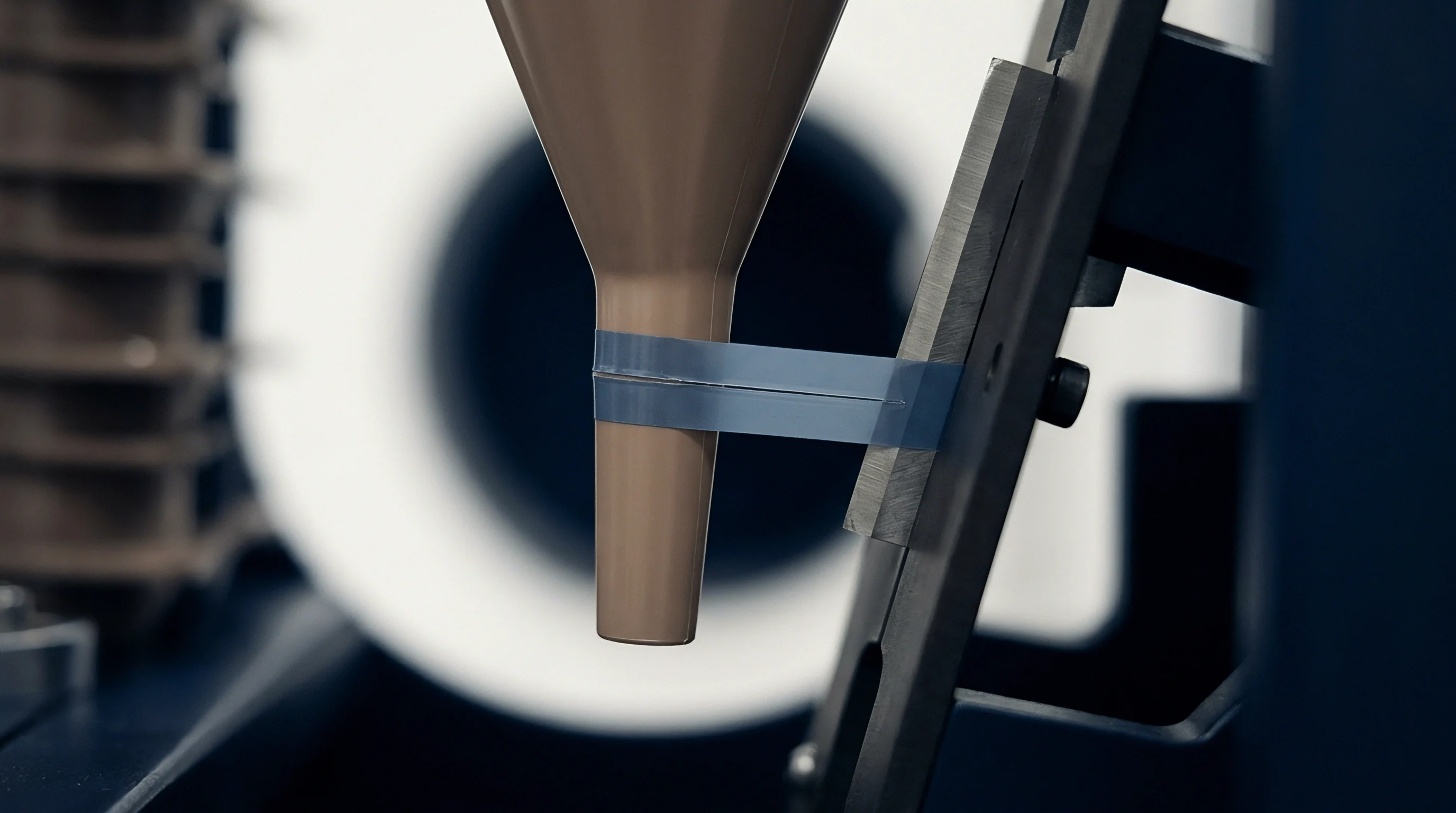
Fluid motion at the interface between molten polymer and steel tool cavity surfaces depends on local shear stress levels. At low to moderate velocity gradients, molten polymer adheres to the metal surface, satisfying the classical no-slip boundary condition. When wall shear stress exceeds critical thresholds, typically ranging between 0.1 MPa and 0.3 MPa depending on polymer chemistry and surface roughness, boundary adhesion breaks down and wall slip initiates.
Wall slip alters the velocity profile across the cavity thickness, flattening the parabolic distribution toward a plug-flow profile. This change in flow kinematics reduces localized shear rates near the wall while increasing bulk flow velocity through the core. Calculating true shear rates under wall slip conditions requires applying the Rabinowitsch correction to apparent capillary flow data:
γ̇_w = (γ̇_app / 4)
Correcting for non-Newtonian behavior via Rabinowitsch adjustments ensures accurate mapping of wall shear stress against volumetric flow rates, isolating slip velocity components from fluid shear thinning.
- Mount the multi-bore capillary rheometer equipped with identical diameter dies possessing land length ratios of 10:1, 20:1, and 30:1.
- Heat the barrel and test dies to the target processing temperature, maintaining a thermal stabilization window of twenty minutes prior to testing.
- Execute piston speed sweeps to generate apparent shear rates ranging from 500 s^-1 to 50,000 s^-1 across each die length.
- Construct Bagley plots of total pressure drop versus die length-to-diameter ratio to isolate true entrance pressure losses from wall shear stresses.
- Calculate slip velocities using the Mooney method by plotting apparent shear rate against reciprocal die diameter at constant true wall shear stress levels.
Solidification kinetics near tool walls depend heavily on wall slip and local wall friction coefficients. Early wall slip disrupts the formation of a uniform frozen layer during cavity filling, causing surface defects including jetting, sharkskin matte finishes, and weld-line weakness. In semi-crystalline polymers like polypropylene and polyoxymethylene, altered surface shear stress state directly influences nucleation density and spherulite growth rates, producing distinct morphological layers through the part cross-section.
Extensional viscosity during convergent flow into narrow gate lands generates pressure losses exceeding fifty percent of total cavity fill resistance.
Inserting standard ISO 11443 capillary test clauses into resin procurement agreements establishes clear boundaries for wall shear stress compliance, requiring compounders to document exact wall slip onset thresholds before supplying high-shear molding lots.

Swell
Polymer melts exhibit non-linear viscoelasticity due to long-chain entanglements that store mechanical energy as elastic strain during flow through restricted geometries. When melt exits a constrained gate land into a wider mold cavity, stored elastic energy releases rapidly, causing cross-sectional expansion known as extrudate die swell. The ratio of expanded extrudate diameter to die diameter increases with elevated flow rate until molecular relaxation mechanisms relieve normal stress differences.
Viscoelastic strain storage relates directly to the First Normal Stress Difference (N1), which develops perpendicular to the primary flow direction under high velocity gradients:
N₁ = τ₁₁ – τ₂₂
High normal stress differences generate large entrance pressure drops (ΔPe) as melt converges from the runner channel into a pin gate. Short land lengths prevent polymer chains from relaxing before entering the cavity, amplifying die swell and causing jetting streams that fold over themselves rather than expanding smoothly along cavity walls.
| Resin Designation | Fill Type | Gate L/D Ratio | Entrance Pressure Drop (MPa) | Die Swell Ratio B |
|---|---|---|---|---|
| Unfilled | 2:1 | 14.2 | 1.68 | |
| Unfilled | 8:1 | 6.1 | 1.22 | |
| 30% Glass Fiber | 2:1 | 22.5 | 1.08 | |
| 30% Glass Fiber | 8:1 | 11.8 | 1.02 |
Optimizing gate geometry requires extending the land length to diameter ratio (L/D) to at least 2.5:1, providing sufficient residence time for molecular relaxation while maintaining shear heating within safe thermal bounds.
Extending gate land lengths beyond optimum thresholds increases friction without improving swelling metrics once molecular stress relaxation plateaus.

Qualification

Where Does Single-Point Melt Index Fail High Shear Molders?
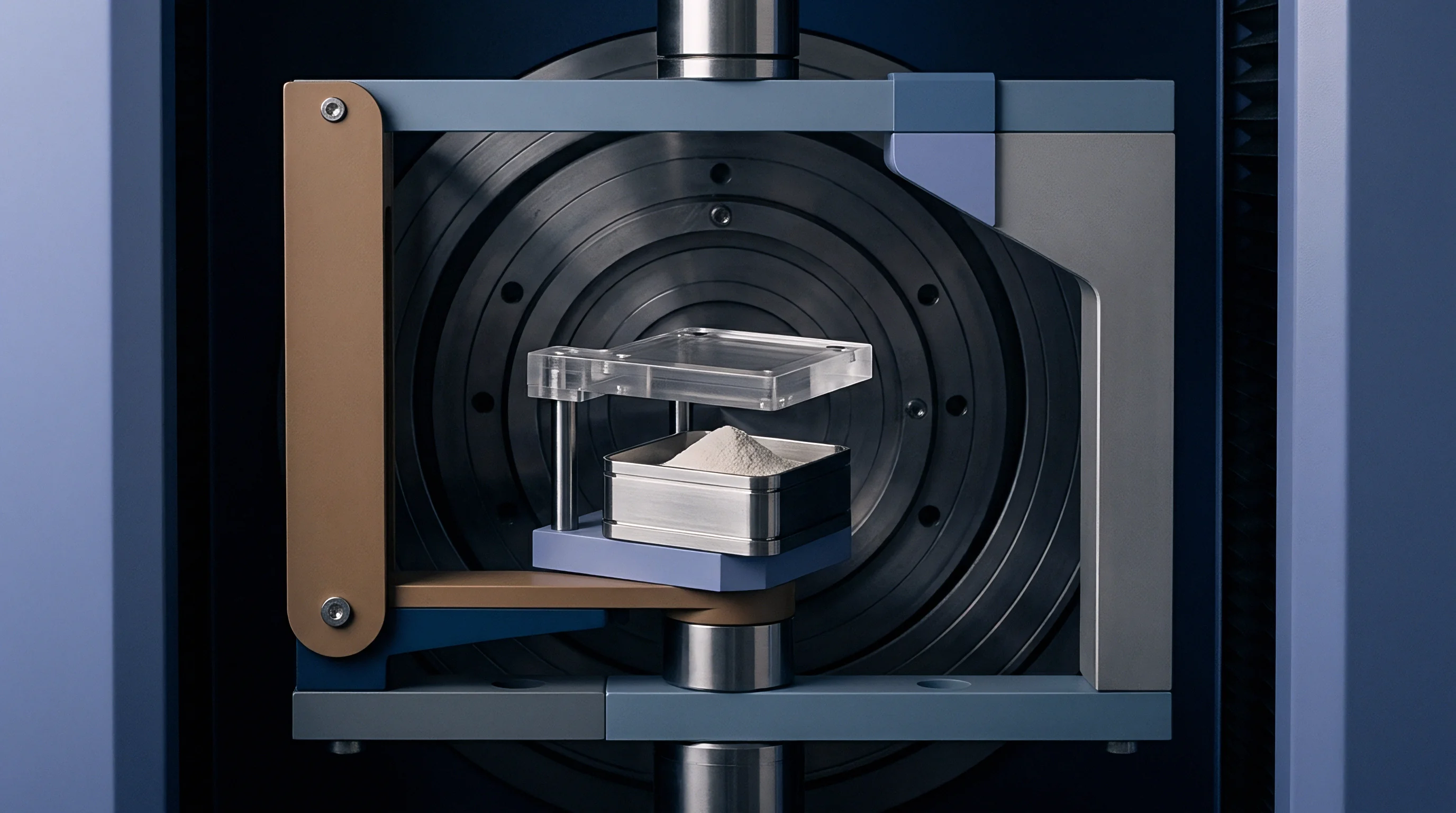
Single-point Melt Flow Rate (MFR) testing performed per ISO 1133 or ASTM D1238 applies low, static shear stresses using dead-weight loads such as 2.16 kg or 5.0 kg. These conditions produce apparent shear rates between 10 s^-1 and 100 s^-1, capturing material behavior strictly within or near the zero-shear Newtonian plateau. High-speed injection molds operate four orders of magnitude higher on the rheological spectrum.
Two resin lots exhibiting identical MFR values of 15 g/10 min at low shear rates often possess drastically different molecular weight distributions (MWD). Broad MWD resins contain high molecular weight tails that increase zero-shear viscosity but display dramatic shear thinning under high shear rates. Narrow MWD grades exhibit flatter viscosity curves, yielding higher resistance inside high-shear pin gates despite identical single-point MFR numbers.
Contractual specification of ISO 11443 high-shear viscosity boundaries protects molders against lot substitutions that meet low-shear melt flow index targets while failing tool fill requirements.
Establishing incoming material verification procedures mandates multi-point high-shear characterization using capillary rheometers equipped with zero-length dies to isolate true shear viscosity from extensional entrance effects.
- Shear Viscosity Curve Compliance ~ Require multi-point capillary viscosity data across four shear rates between 1,000 s^-1 and 50,000 s^-1 prior to signing resin supply contracts.
- Thermal Stability Verification ~ Test viscosity retention after ten minutes of isothermal residence at maximum projected shear-heated melt temperatures.
- Bagley Pressure Drop Limits ~ Establish maximum allowable entrance pressure loss thresholds to prevent premature hydraulic pressure capping on injection machines.
- Extrudate Swell Allowance ~ Specify maximum extrudate swelling ratios to prevent gate vestige distortions and localized shear-induced surface clouding.
A critical unresolved question centers on whether compounders can reliably balance broad molecular weight distributions to achieve aggressive high-shear thinning without compromising long-term environmental stress crack resistance in thin-wall structural parts.

Tonnage
Determining required machine clamping force in high-shear molding applications demands accurate cavity pressure integration based on shear-thinning apparent viscosity rather than baseline resin datasheets. Standard clamping force estimates using static mid-cavity pressure assumptions overestimate required tonnage when high velocity gradients lower effective melt viscosity throughout the runner and gate system. Conversely, underestimating entrance pressure losses at sub-gates causes hydraulic pressure capping, where the injection unit reaches maximum pressure output before cavity filling completes, producing short shots despite high clamping capacity.
Tooling wear mechanisms escalate rapidly when processing mineral or glass-reinforced compounds under high shear velocities. Fiber-filled polyamides pushed through sub-1.0 mm gates at shear rates exceeding 30,000 s^-1 induce severe hydro-abrasive wear along gate entry lips and land surfaces. High shear stresses strip matrix polymer from glass fiber surfaces, turning the filler material into an abrasive slurry that erodes hardened tool steel over repeated cycles.
Tool wear alters gate geometry over time, increasing cross-sectional land areas and lower local shear rates. This geometrical enlargement shifts the viscous dissipation profile, increases apparent melt viscosity, and alters cavity fill patterns. Operating electric or hydraulic presses under closed-loop velocity control compensates for shifting gate pressure drops by increasing hydraulic force, which accelerates tool degradation if gate steel hardness drops below 54 HRC.
Balancing part manufacturing unit costs against tool refurbishing frequency establishes the true commercial boundary for high-shear resin selection.