Evaluating Polymer Rheology Mismatch in Additive Carrier Resin Selection
Match high-shear viscosity profiles and elasticity ratios rather than plastometer values to prevent phase separation and ensure complete additive dispersion.


Viscosity

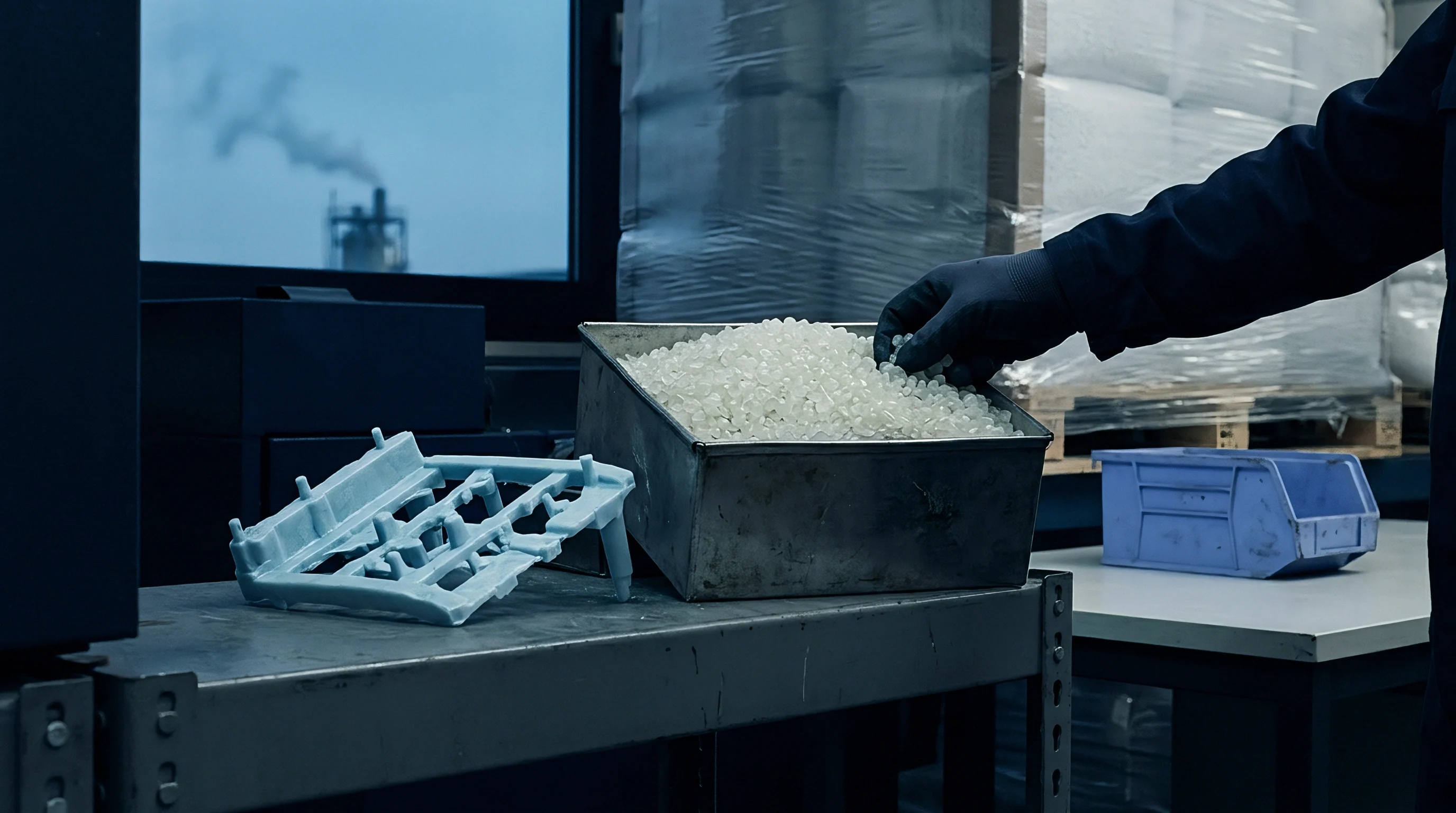
Melt Index Limitations
A single melt flow rate figure on a masterbatch technical data sheet masks the true behavior of molten polymer under shear. Standard quality control protocols rely on ASTM D1238 or ISO 1133 Procedure A, reporting a gravimetric value in grams per 10 minutes at a single temperature and deadweight load. A polyolefin additive concentrate displaying 20 g/10 min under 2.16 kg at 190 °C can match a matrix polymer on paper while behaving erratically in the extruder.
The deadweight piston of an extrusion plastometer subjects the fluid to an apparent shear rate rarely exceeding 10 reciprocal seconds. Industrial single-screw and twin-screw extruders operate at wall shear rates between 100 and 1,000 reciprocal seconds, while injection mould gates exceed 10,000 reciprocal seconds. Viscosity curves cross as shear thins each grade at different rates.
Zero-shear viscosity tracks weight-average molecular weight, whereas high-shear viscosity depends heavily on molecular weight distribution and chain branching. An additive carrier formulated with broad molecular weight distribution exhibits steep shear thinning. A narrow distribution matrix resin, such as a metallocene-catalyzed linear low-density polyethylene, exhibits a flatter viscosity curve across the same processing window.
Matching a carrier resin to a base resin via plastometer values guarantees mismatch across the actual processing screw. The compounding line produces non-uniform additive distribution whenever these shear responses diverge.
A single melt flow index measured at low shear fails to predict high-shear dispersion behavior in industrial tool gates.
Capillary Rheometry Profiles
Evaluating true flow compatibility requires high-pressure capillary rheometry according to ASTM D3835 or ISO 11443. Capillary testing evaluates apparent shear rates from 10 to 10,000 reciprocal seconds using tungsten carbide dies with length-to-diameter ratios of 20:1 or 30:1. The Bagley correction subtracts entry pressure losses, while the Rabinowitsch correction resolves true shear rates for non-Newtonian fluids.
Plotting true shear viscosity against true shear rate establishes the viscosity ratio across operating zones.
The viscosity ratio, defined as carrier viscosity divided by matrix polymer viscosity at processing shear rates, determines droplet deformation and breakup. Capillary rheometry confirms that the viscosity ratio shifts across the screw length as temperature and shear fields evolve. A carrier resin displaying an ideal viscosity ratio of 0.8 at 100 reciprocal seconds in the metering zone can drop below 0.1 at 5,000 reciprocal seconds in the injection gate.
The compounder evaluates both components across the specific shear profile of the target equipment.
Process instability follows when the viscosity ratio drifts outside the laminar breakup window. A supplier routinely reports that carrier viscosity matches standard processing parameters without presenting capillary data.


Interface

Droplet Deformation Mechanics
Taylor droplet breakup theory governs the dispersion of additive-rich carrier phases inside the molten polymer matrix. When an additive masterbatch melts, it forms discrete domains within the continuous phase of the base resin. The capillary number balances viscous shear stresses against interfacial tension:
Ca = (ηm · γ̇ · R) / σ
Here, ηm represents the continuous matrix viscosity, γ̇ is the shear rate, R is the droplet radius, and σ is the interfacial tension. Breakup requires the capillary number to exceed a critical value, Cacrit, which depends directly on the viscosity ratio (λ = ηd / ηm, where ηd is the dispersed carrier viscosity). Grace curves demonstrate that droplet breakup occurs most efficiently when λ falls between 0.1 and 1.0.
Shear flow cannot break droplets when λ exceeds 3.8. Elongational flow extends this limit, though it demands higher specific mechanical energy.
| Carrier Chemistry | Matrix Resin | Viscosity Ratio (λ) at 500 s⁻¹ | Interfacial Tension (mN/m) | Critical Capillary Number (Ca_crit) |
|---|---|---|---|---|
| LDPE (Autoclave, broad MWD) | LLDPE (C4 copolymer) | 0.45 | 1.8 | 0.52 |
| LLDPE (Ziegler-Natta) | HDPE (Blow moulding grade) | 0.12 | 2.4 | 0.78 |
| PP Homopolymer (MFR 12) | PP Copolymer (MFR 2.0) | 0.28 | 1.2 | 0.48 |
| EVA (18% Vinyl Acetate) | PP Homopolymer (MFR 3.5) | 0.62 | 4.6 | 0.95 |
| HDPE (High MFR carrier) | PP Copolymer (MFR 1.5) | 2.10 | 5.8 | 2.80 |

Coalescence Kinetics
Droplet coalescence opposes dispersion throughout the melt conveyance zone. If the carrier resin exhibits lower viscosity than the base polymer, the additive-rich domains deform into thin sheets or fibrils. High interfacial tension pulls extended fibrils back into spherical domains during transit through low-shear sections, including adapter pipes and transfer lines.
Coalescence rate scales inversely with matrix viscosity and increases with higher carrier volume fractions. Masterbatches let down at 5% volume fraction resist coalescence far better than concentrates fed at 15% loading.
When the carrier resin possesses an excessively low melt elasticity, droplets coalesce immediately after exiting high-shear mixing elements. The dispersed phase coarse-grains. Pigments or active chemical stabilizers remain trapped inside un-sheared carrier pockets rather than transferring across the phase boundary into the base resin matrix.
Non-homogeneous stabilizing packages leave unshielded volumes of the primary polymer vulnerable to thermo-oxidative degradation.
Incompatible interfacial properties trigger visual defects and localized mechanical failure points across the finished part. Non-homogeneity yields micro-voids, optical haze variations, and erratic tensile strength values.


Phase

How Do Elasticity Differences Force Phase Inversion?
Melt elasticity governs normal stresses developed during non-Newtonian flow. The first normal stress difference, N1, quantifies the elastic force driving polymer melt away from shearing surfaces. When a carrier resin and a matrix resin display matched shear viscosities, differing elasticities still drive spatial separation.
High-elasticity polymers generate significant normal stresses, migrating toward regions of lowest shear rate, typically the core of a circular flow channel. Low-elasticity polymers migrate toward high-shear wall regions.
Unequal normal stresses shift phase inversion thresholds away from classic volume-fraction predictions. Phase inversion normally occurs when the volume ratio matches the viscosity ratio:
(φ1 / φ2) = (η1 / η2)a
Elasticity differentials alter exponent a. A carrier resin carrying lower elasticity than the matrix concentrates at the barrel wall, encapsulating the base resin even at volumetric concentrations below 10%. The additive carrier then lubricates the wall, suppressing viscous dissipation and dropping mechanical shear energy across the screw root.
Melt temperature drops. Unmelted additive agglomerates pass through unhindered.
Elastic normal stress differences displace low-viscosity additive carriers toward tool walls, suppressing the mechanical shear necessary for dispersion.

Extensional Viscosity Contrast
Shear fields represent only part of the stress experienced during processing; converging geometries introduce extensional deformation. Extensional viscosity curves measured via Cogswell calculations or filament stretching rheometry reveal strain-hardening characteristics. Low-density polyethylene synthesized via high-pressure tubular or autoclave reactors exhibits strain hardening due to long-chain branching.
Linear polyethylenes and polypropylenes soften under equivalent extensional strain.
Introducing an autoclave LDPE additive carrier into a metallocene LLDPE matrix introduces sharp extensional rheology contrasts. When the melt enters converging mould gates or extrusion dies, the strain-hardening LDPE droplets resist elongation, while the matrix stretches freely. High local stress gradients develop at the droplet-matrix boundary, triggering debonding and micro-cavitation.
These micro-cavities reflect light, producing surface haze in blown film applications.
Uncontrolled extensional mismatch degrades surface appearance and tears thin webs during high-speed film line draw-down. Standard procurement specifications omit extensional rheology thresholds, leaving converter operations exposed to unmonitored material variations.

Friction

Screw Flight Dynamics
Solid-state conveying in the extruder feed zone relies on friction against the barrel wall. The polymer must stick to the barrel and slip on the screw surface for forward conveying to function per Darnell-Mol mechanics. Masterbatch pellets melt according to their respective melting temperatures and crystallization kinetics.
If the additive carrier melts early due to lower molecular weight or lower melting points, it coats solid base resin pellets in the compression zone. Premature surface melting generates liquid lubrication.
This lubrication reduces the coefficient of dynamic friction between the solid bed and the heated barrel wall. The solid bed slips. Forward conveying slows, generating severe head-pressure instability and erratic motor amp draws.
The screw flight fails to push the polymer forward against backpressure generated by screen packs and breaker plates.
Consider an injection moulding cell running a polypropylene copolymer packaging part with a dry-blended 3% slip-antioxidant masterbatch. The matrix resin is an extrusion-grade heterophasic copolymer with an MFR of 1.8 g/10 min (ISO 1133, 230 °C, 2.16 kg). The masterbatch uses an injection-grade PP homopolymer carrier with an MFR of 25 g/10 min (ISO 1133, 230 °C, 2.16 kg).
The barrel profile runs 190 °C at Zone 1 up to 230 °C at the nozzle. Total shot weight measures 450 grams, and target recovery time runs at 8.2 seconds.
Because the carrier melts rapidly in Zone 1, molten resin coats un-melted matrix pellets. Screw recovery time shifts from 8.2 seconds to 12.4 seconds, with shot-to-shot variance reaching ±1.8 seconds. Friction loss across the solids conveying zone slows plasticizing rates.
The mould cycle expands from 14.5 seconds to 18.7 seconds. Over a production run of 100,000 units on a machine operating at an hourly rate of $85.00, this cycle extension adds 116.6 machine hours. The rheology mismatch in the carrier increases operational processing costs by $9,911, far exceeding the minor price difference of matching the carrier grade properly.

Feed Throat Segregation
Bulk density and pellet geometry interact with frictional properties inside gravimetric blenders and feed throats. Rheological tailoring often requires masterbatch suppliers to use high-flow carrier resins, yielding low-viscosity strands during compounding that water-cut into tiny micro-pellets. Matrix resins arrive as standard cylindrical or spherical pellets measuring 3 to 4 mm in diameter.
Micro-pellets display higher bulk densities and lower angles of repose.
Percolation segregation occurs inside hoppers subjected to machine vibration. Micro-pellets sift downward through the interstitial spaces of the base resin pellets. The effective masterbatch feed concentration spikes, cycling between starved conditions and over-concentration.
The screw encounters fluctuating melt viscosities, destabilizing the thermal profile. The machine operator registers erratic screw recovery and surging melt pressures.
Incoming inspection procedures require tracking pellet dimension and bulk density alongside thermal characteristics. The following quality checkpoints isolate solid conveying defects before charging silos:
- Pellet count verification tracks granules per gram via automated optical counting to ensure dimensional compatibility with matrix resin feeds.
- Bulk density testing per ASTM D1895 identifies segregation risk in gravimetric blender hoppers before processing commences.
- Differential scanning calorimetry reveals crystallization temperature and early melting peaks that signal premature melting in the feed throat.
- Melt flow verification under dual-load testing per ISO 1133 confirms whether high-shear thinning indices match incoming masterbatch certificates of analysis.
Operating without strict dimensional and thermal tolerances risks recurring feeding instability across continuous extrusion lines.

Testing

High Shear Rate Capillary Protocols
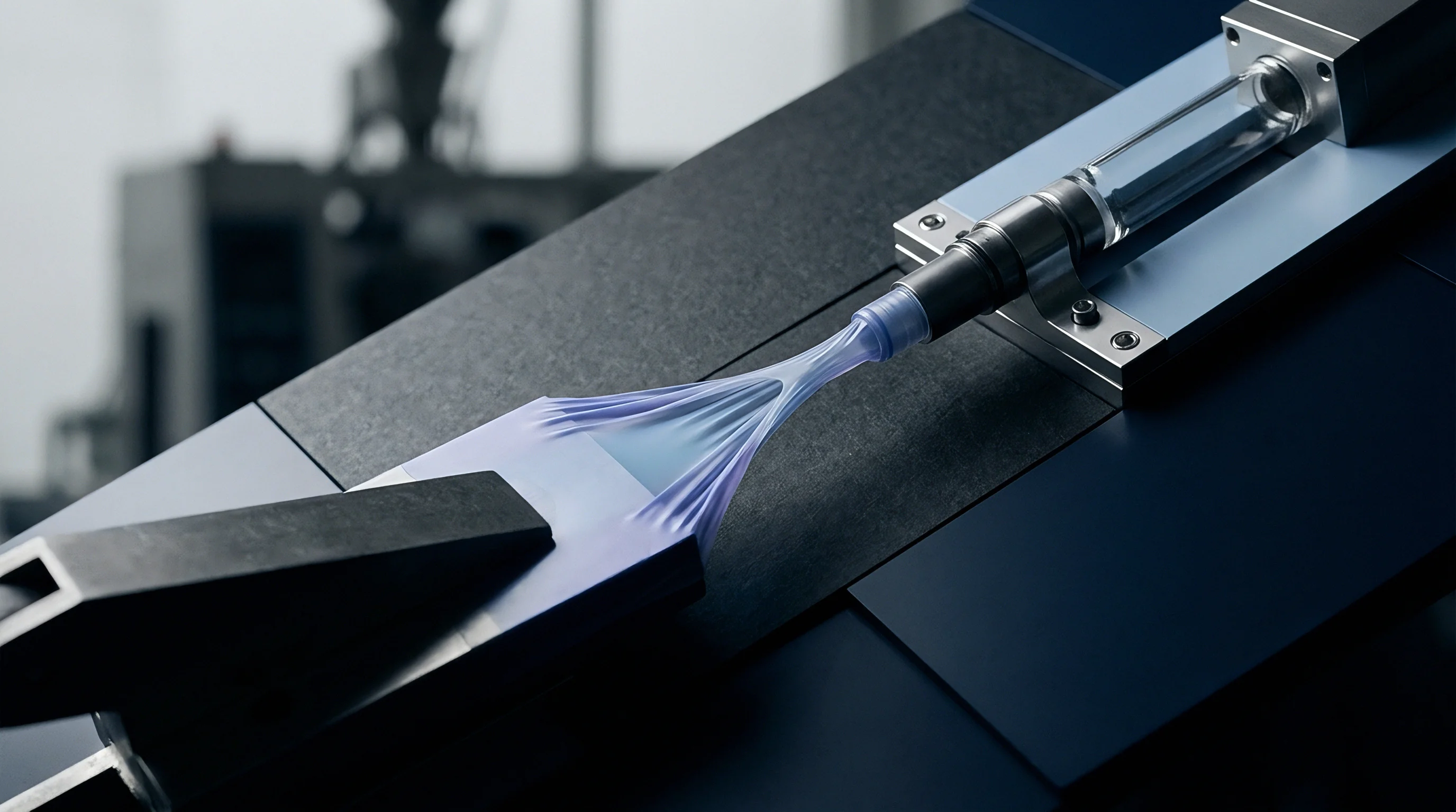
Incoming inspection of additive concentrates requires capillary testing that reflects operational shear rates. A twin-bore capillary rheometer isolates viscosity and elasticity simultaneously. One barrel houses a long die (30:1 L/D), while the adjacent barrel houses an orifice die (zero-length) to calculate Bagley entrance corrections in real time.
Testing covers apparent shear rates of 100, 500, 1,000, 5,000, and 10,000 s⁻¹ at standard melt processing temperatures.
A masterbatch must be tested at its concentration in the carrier, alongside a neat sample of the matrix polymer. Evaluating the masterbatch alone is insufficient because high additive loadings ~ such as 60% calcium carbonate or 40% carbon black ~ alter the flow curves of low-viscosity carrier resins. Solid filler particles elevate yield stress and restrict polymer chain mobility.
The composite masterbatch viscosity curve determines the true viscosity ratio inside the processing screw.
| Resin Identity | Viscosity at 100 s⁻¹ (Pa·s) | Viscosity at 500 s⁻¹ (Pa·s) | Viscosity at 1,000 s⁻¹ (Pa·s) | Viscosity at 5,000 s⁻¹ (Pa·s) |
|---|---|---|---|---|
| Matrix: LLDPE Film Grade (MFR 1.0) | 1,420 | 510 | 320 | 105 |
| Carrier A: LDPE (MFR 2.0) | 1,100 | 340 | 195 | 52 |
| Carrier B: LLDPE (MFR 20.0) | 210 | 95 | 62 | 24 |
| Carrier C: HDPE (MFR 7.0) | 680 | 240 | 150 | 58 |
| Masterbatch: 50% TiO2 in Carrier B | 890 | 310 | 180 | 55 |

Rotational Rheometry and Modulus Crossover
Small-amplitude oscillatory shear testing on parallel-plate rotational rheometers clarifies viscoelastic dynamics below polymer degradation thresholds. ASTM D4440 protocols dictate testing across an angular frequency range from 0.1 to 500 rad/s under nitrogen purge. This analysis isolates storage modulus (G′), loss modulus (G″), and complex viscosity (η ).
The Cox-Merz rule equates complex viscosity with steady shear viscosity for unmodified linear polyolefins, though filled systems show deviations.
The modulus crossover point (G′ = G″), where tan δ = 1, establishes molecular weight distribution breadth and mean chain length. Higher crossover frequencies indicate lower molecular weight. Lower crossover moduli indicate broader molecular weight distributions.
Matching crossover coordinates between carrier and matrix resins prevents phase separation caused by elastic normal stress imbalances.
When the carrier resin displays a crossover modulus significantly lower than the matrix polymer, elastic segregation occurs inside the mould. Dynamic mechanical measurements provide the precise viscoelastic parameters needed to prevent these failures.
Oscillatory frequency sweeps confirm that matched crossover points eliminate elastic segregation during non-isothermal mould filling.
Dilute Solution Viscometry
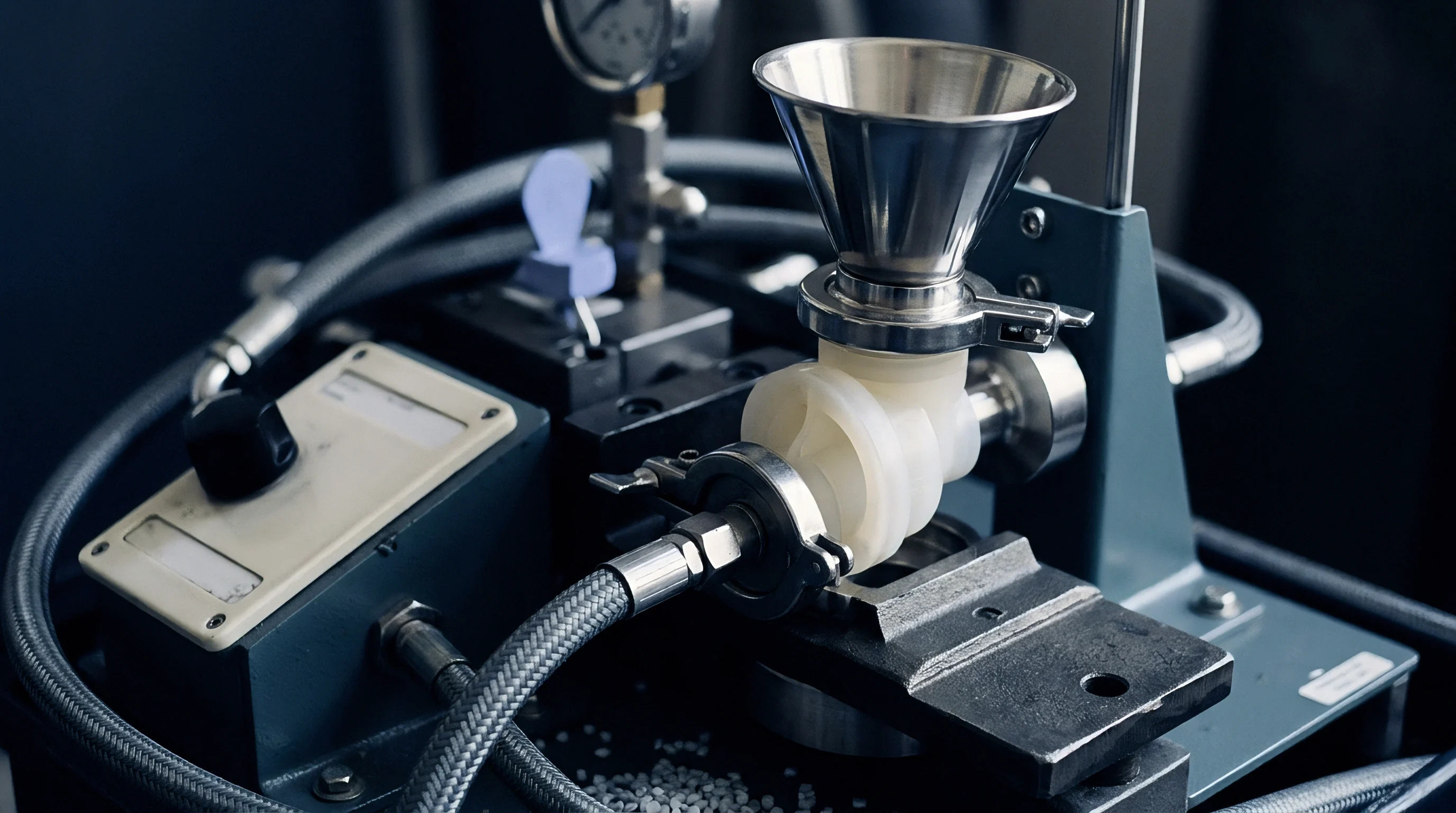
High-temperature gel permeation chromatography and dilute solution viscometry verify underlying polymer chain architectures. Standard ASTM D1601 measures intrinsic viscosity of polyethylenes dissolved in decahydronaphthalene at 135 °C. Intrinsic viscosity relates directly to viscosity-average molecular weight via the Mark-Houwink equation:
= K · Mva
Parameters K and a shift based on chain branching. An autoclave LDPE carrier yields a lower intrinsic viscosity than an LLDPE carrier of identical weight-average molecular weight due to long-chain branching. Dilute solution metrics expose substitutions where suppliers blend ultra-low-viscosity waxes into broad-spec resins to hit target melt flow index specifications.
A supplier rarely reveals wax additions on technical datasheets. Solution viscosity tests unmask low-molecular-weight fractions that migrate to tool surfaces and cause die lip build-up.


Purge
Boundary Layer Accumulation
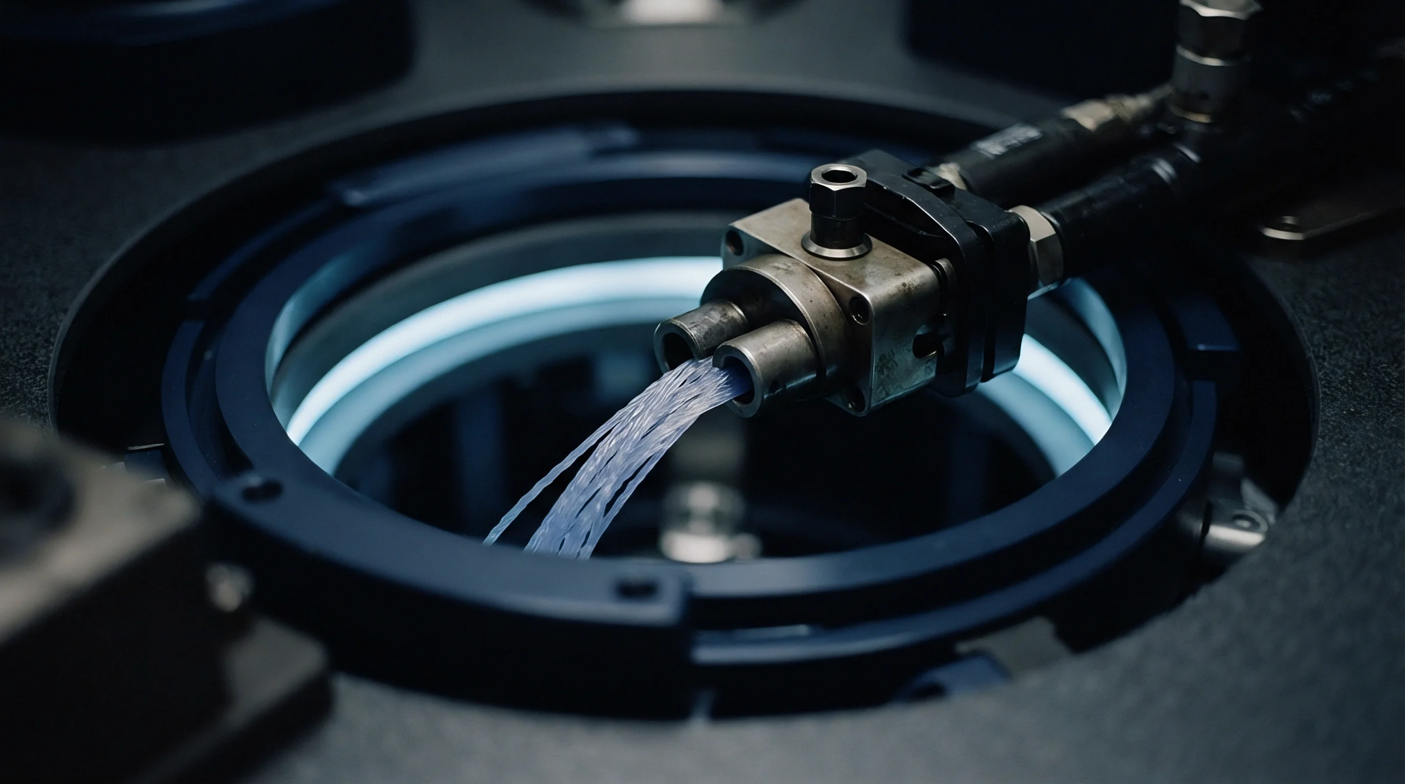
Incompatible rheology causes additive carriers to deposit along internal flow paths. In crosshead dies, sheet extrusion heads, and hot runner manifolds, melt velocities drop to zero at metallic boundaries. Low-viscosity components enter these low-velocity boundary layers through shear-induced phase migration.
Additive carrier resins with excessive flow rates accumulate along steel walls instead of moving with the bulk stream.
Trapped in the boundary layer, the carrier experiences prolonged residence times at processing temperatures. Additives, thermal stabilizers, and processing aids degrade under extended heat exposure. Degraded polymers crosslink or scission, creating carbonaceous crusts inside hot runner drops and extrusion adaptors.
Periodic shear fluctuations tear small portions of this degraded layer away, depositing black specks directly into the part.
Clearing degraded carrier deposits requires abrasive mechanical purges or high-viscosity chemical purge compounds. Standard resin flushes glide over low-viscosity wall deposits without transferring sufficient shear stress to dislodge them.

Die Drool Dynamics
Die drool, or die lip build-up, stems directly from rheological mismatch between additive carriers and matrix polymers. Highly mismatched low-molecular-weight carriers fracture along the exit die lip due to abrupt stress transitions from wall-shear to free-surface conditions. The polymer experiences exit singularities where tensile and shear stresses reach local maximums.
Low-viscosity fractions, processing waxes, and volatile additives separate from the primary stream, gathering at the outer metallic edge of the die. Atmospheric oxygen crosslinks and degrades these accumulations into rigid deposits. The extrudate scrapes against the build-up, forming continuous drag lines, die lines, and localized surface pinholes along extruded sheet or profile surfaces.
Cleaning die lips interrupts continuous operations, increasing machine downtime and generation of scrap material. Converters face high labour costs and lost throughput when line stops are required to scrub tooling manually.
The standard supply agreement clause stipulating that materials run cleanly across commercial equipment fails to compensate converters for scrap rates generated by unmonitored carrier degradation.


Reclaim
Chain Scission Dynamics in Recycled Streams
Mechanical recycling loops multiply rheological mismatches inside industrial compounds. Post-consumer and post-industrial polyolefin streams contain repeated thermal histories. Each extrusion pass induces chain scission in polypropylene and crosslinking or scission in polyethylene, shifting the primary resin viscosity downwards.
Compounding additives into these degradation-shifted streams demands precise carrier resin adjustments.
Virgin additive concentrates designed for prime resins fail inside degraded recyclate streams. A masterbatch formulated with an MFR 20 carrier causes dispersion failure in a post-consumer PP stream degraded from MFR 3 to MFR 35. The viscosity ratio inverts, leaving high-shear mixing zones unable to break up concentrated antioxidant and pigment agglomerates.
The resulting compound displays diminished impact strength and embrittlement.
Compounders adjust carrier specifications to balance incoming feed fluctuations. Stabilizer concentrates formulated in high-viscosity carriers maintain the necessary shear stress to disperse functional additives into low-viscosity recyclate streams.

Lot-to-Lot Melt Flow Variance
Recycled resin streams carry wide lot-to-lot melt flow variations. Sourcing departments balance these fluctuations through rigorous incoming acceptance protocols. Sourcing contracts must account for these variations by specifying strict rheological criteria:
- Incoming lot sampling pulls five composite core samples per 20-tonne truckload to test for melt flow rate variance across batches.
- MFR acceptance bands enforce a tight ±10% tolerance limit around nominal specifications instead of accepting broad generic grades.
- Dual-rate verification measures viscosity at both low and high loads to identify wide molecular weight distributions in blended streams.
- Contaminant screening runs differential scanning calorimetry to detect trace polymer cross-contamination that alters carrier compatibility.
Processing unverified recycled streams leads directly to erratic dispersion and unpredictable finished part performance.
The operational limits of current testing leaves open whether inline ultrasonic or rheological die sensors can reliably correct for rapid carrier viscosity drift in real-time compounding operations.