Viscoelastic Relaxation and Core Thermal Gradients in Heavy Gauge Thermoforming Operations
Heavy gauge thermoforming demands isothermal sheet heating and controlled active tool cooling to eliminate viscoelastic memory recoil and thermal gradient warp.
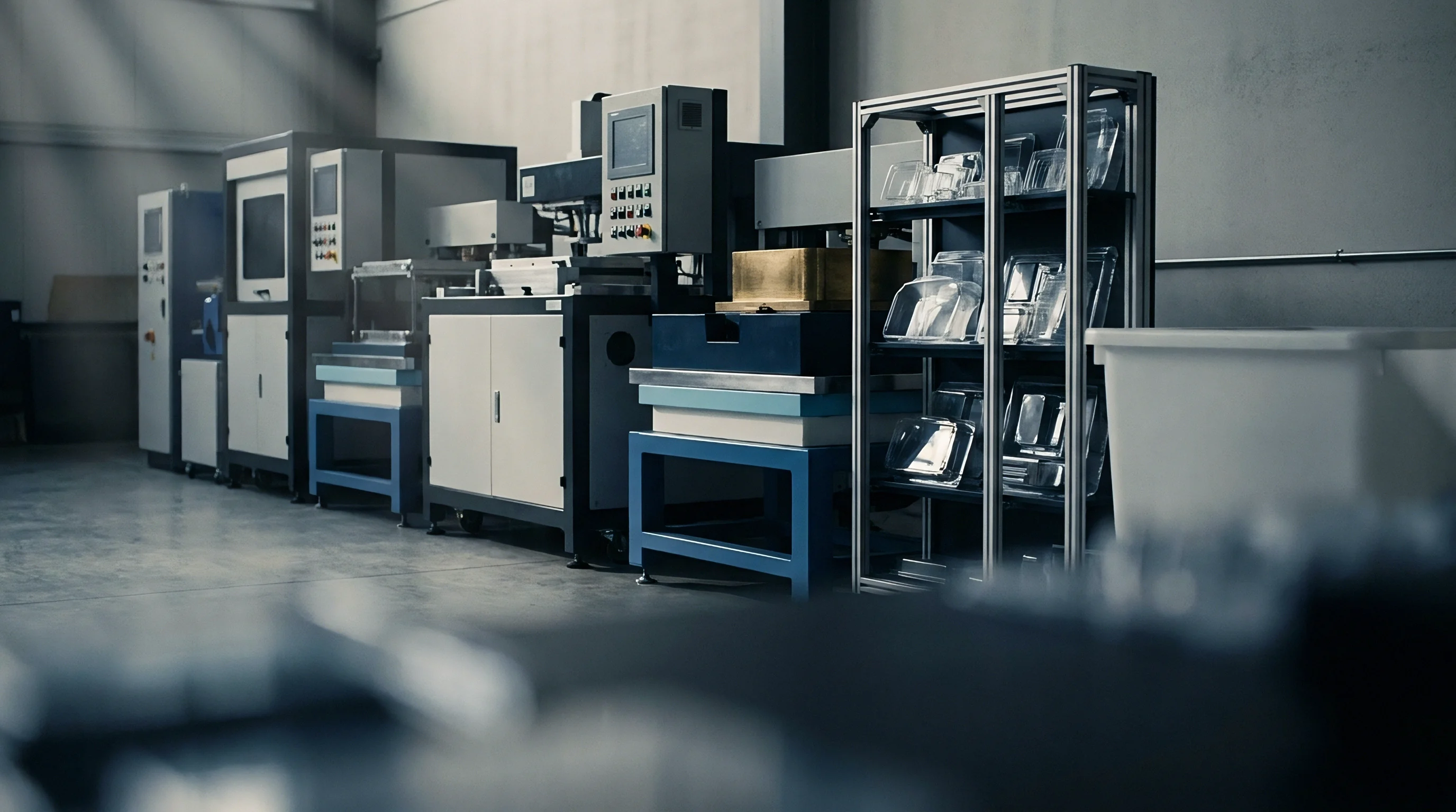

Slab
Extruded thermoplastic sheet stock ranging from 3.0 mm to 12.7 mm in nominal thickness presents physical challenges during radiant thermal conditioning. Heat moves slowly through heavy gauge thermoplastic stock. Polymer resins possess low thermal conductivity values, generally sitting between 0.15 W/m K and 0.22 W/m K for amorphous grades like acrylonitrile butadiene styrene and polycarbonate, and up to 0.48 W/m K for semicrystalline grades like high-density polyethylene.
When radiant energy strikes the exterior face of heavy stock, energy absorption occurs within a micro-thin boundary layer. Heat transport into the interior core relies almost entirely on molecular thermal conduction. Applying aggressive heater power densities to shorten total heating cycle time raises surface temperatures past thermal degradation thresholds long before the core reaches a mouldable, viscoelastic state.
Thickness variations across extruded sheet stock compound core heating discrepancies. Extrusion width tolerances and sheet crown variations create non-uniform thermal mass profiles across the sheet plane. A thickness variance of five percent on a 10 mm sheet alters internal conduction time by over ten percent, as conduction time scales with the square of stock thickness.
When radiant heater banks deliver uniform heat flux across an uneven sheet, thinner regions achieve forming temperature while thicker zones retain cold, rigid cores. These cold cores generate extreme stretching resistance during mould contact, resulting in localized sheet thinning, corner blowout, or incomplete tool reproduction.
Radiant Energy Penetration in Heavy Extrusions
Radiant heaters emit energy across distinct waveband spectra that dictate surface energy absorption efficiency. Medium-wave ceramic elements emit infrared radiation predominantly between 2.0 and 10.0 micrometers, a spectrum where most industrial thermoplastics absorb radiative energy directly at the immediate surface skin. Short-wave quartz halogen elements operate at higher emitter temperatures, shifting peak emission toward 1.0 to 2.0 micrometers.
This shorter wavelength penetrates deeper into semi-transparent and unfilled polymers before total absorption occurs, reducing the thermal slope between exterior skins and interior core layers.
Polycarbonate sheet demands rigorous predrying. Absorptive moisture locked within thick polycarbonate or acrylic stock boils during radiant heating, producing internal micro-voids and optical blistering. When heating heavy gauge polycarbonate, surface moisture outgassing occurs alongside thermal absorption.
Unfilled, clear polymers allow partial infrared energy transmission, whereas carbon-black pigemented or heavily filled sheet stock acts as a blackbody absorber, capturing all infrared energy within the first few microns of the skin layer. Matching infrared element emission spectra to polymer absorption bands remains necessary to minimize severe surface-to-core temperature differentials.
Infrared heater banks using quartz halogen elements reduce surface-to-core heat delivery times by eighteen percent compared to standard medium-wave ceramic panels on thick amorphous sheet.
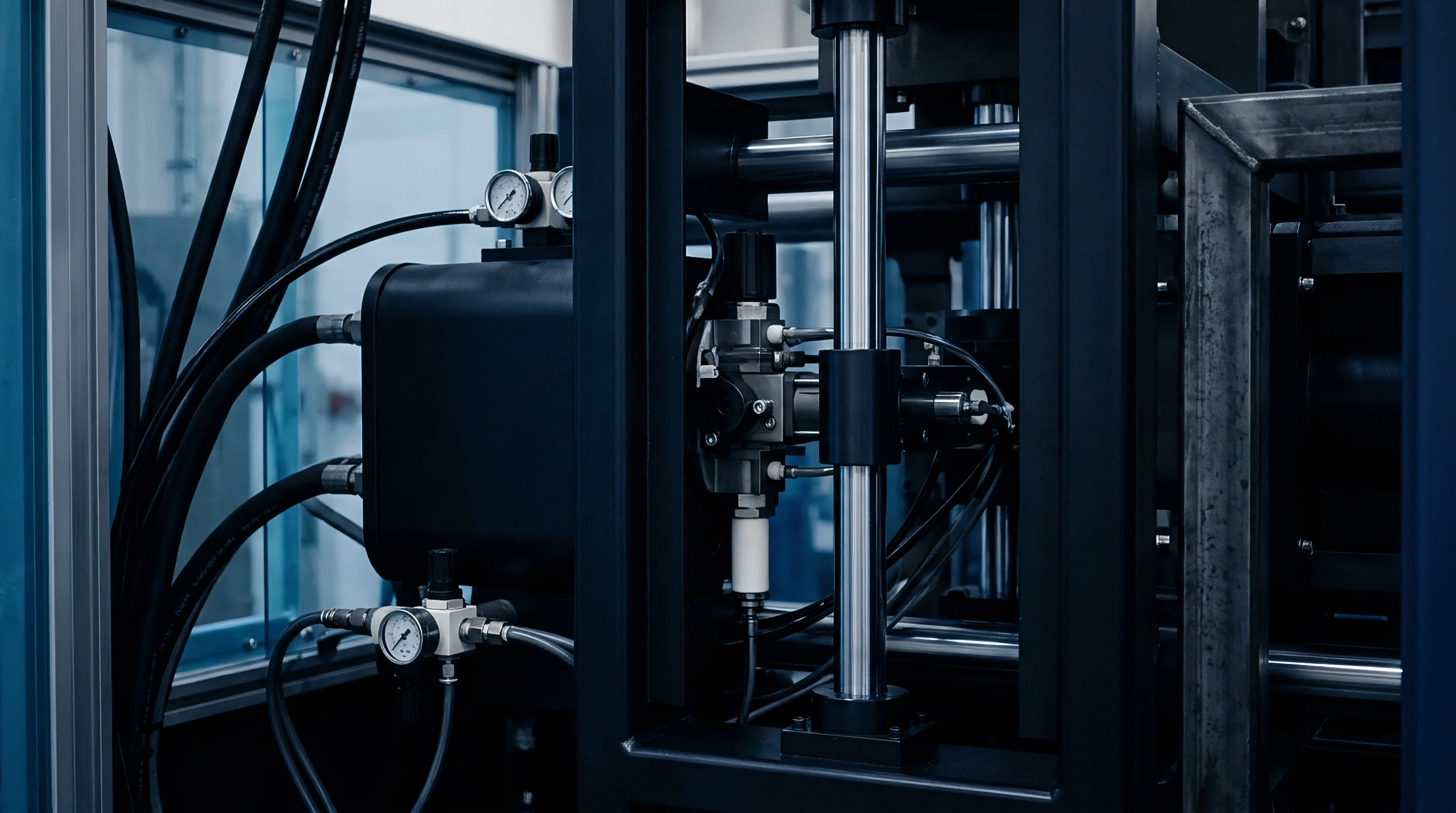
Infrared Emitter Selection and Zoned Surface Control
Top and bottom multi-zone heater ovens provide targeted energy profiles across heavy thermoplastic sheets. Because heated sheet stock expands and sags toward bottom heater elements, distance to lower heat sources continuously decreases throughout the heat cycle. Top heater zones compensate for sag by maintaining elevated heat flux, while bottom zones require precise percentage modulation to prevent localized surface scorching on the downward sag envelope.
Edge heat losses to clamping frames create severe thermal drops along sheet perimeters. Cold clamp jaws pull heat out of adjacent plastic through direct thermal contact, leaving a cold, high-modulus ring around the moldable sheet area. Multi-zone heater controllers overcome perimeter chilling by running outer frame zones ten to twenty-five percent hotter than center sheet zones.
Failure to compensate for edge heat loss restricts sheet draw along boundary walls, transferring strain into the center of the sheet and causing excessive wall variation in formed parts.
- Surface Blistering occurs when radiant heater intensity forces skin temperatures past polymer degradation limits while core layers remain below the glass transition temperature.
- Core Shear Delamination happens during deep-draw plug assist forming when cold internal core layers resist elongation, creating internal planar shear failure between hot outer layers.
- Sag-Induced Thinning develops when bottom sheet surfaces overheat under uncompensated heater banks, causing premature gravitational drop and un-targeted sheet pre-stretching.
- Thermo-Oxidative Surface Degradation arises during extended heating cycles required for thick stock, breaking down polymer chains on outer skins and degrading impact strength.
Suppliers frequently attribute web-tearing and web-thinning across tool corners to uncalibrated resin melt flow indices, when oven balance logs clearly show skin overheating over a cold, unyielding core.
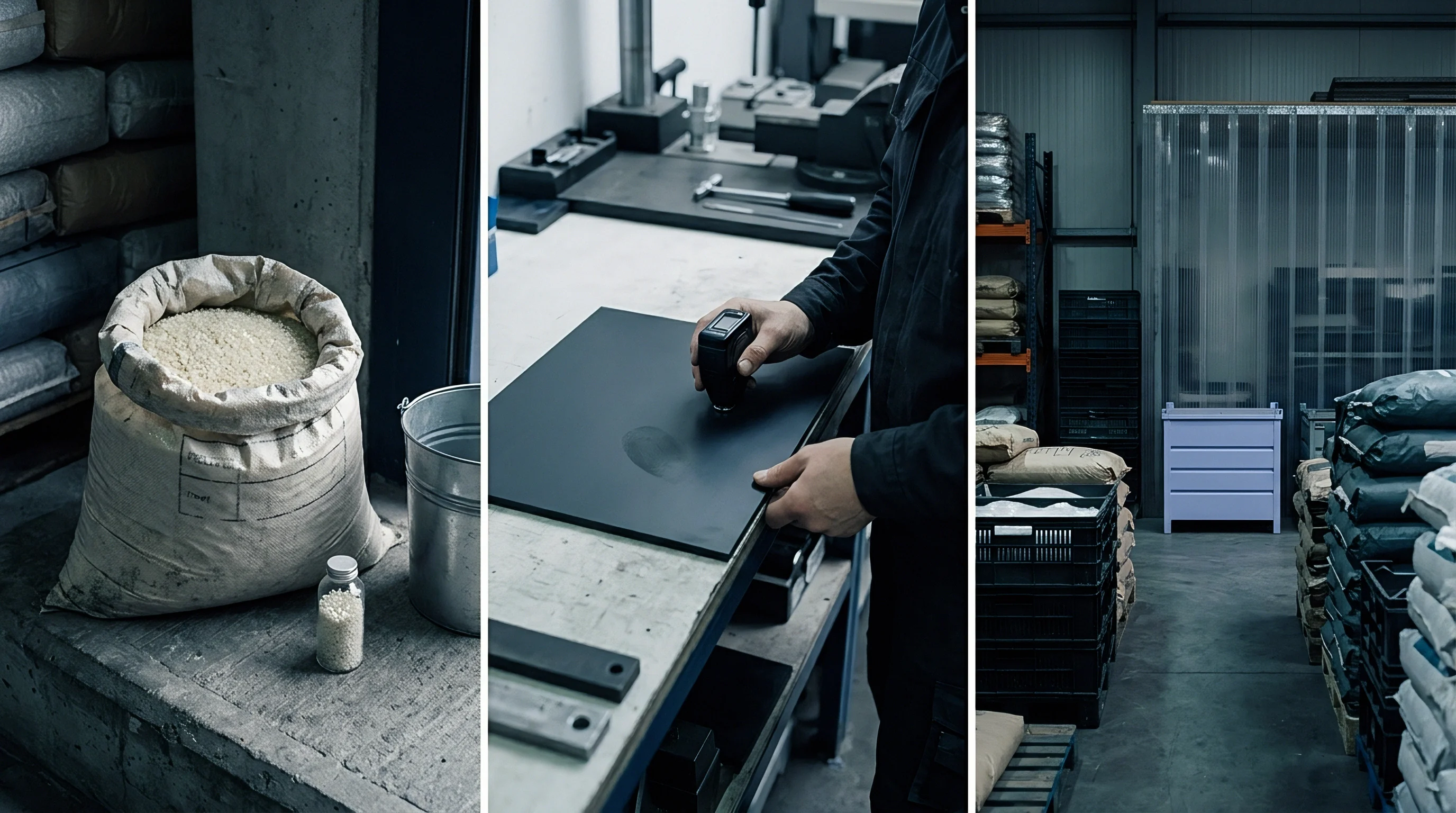
Gradient
Heat transfers through dense polymer matrices strictly by conduction, governed by transient heat conduction equations. The thermal diffusivity constant of a polymer, defined as thermal conductivity divided by the product of density and specific heat capacity, dictates how fast a thermal wave moves from outer skins to the center plane. Amorphous thermoplastics present low thermal diffusivity values, typically hovering around 1.0 x 10^-7 m^2/s.
Consequently, establishing an isothermal state across a 10 mm sheet demands lengthy heating profiles, directly increasing total machine cycle time and piece cost.
When heating thick thermoplastic stock, thermal profiles assume a steep parabolic curve across the sheet cross-section. Surface skins reach target thermoforming temperatures rapidly while the core center lags behind significantly. Surface overheating degrades molecular weight.
Forcing fast heat transfer through elevated surface temperatures causes polymer chain scission, discoloration, and loss of tensile properties on outer surfaces while core temperatures remain below the glass transition point.
Transient Heat Conduction through Thick Polymer Layers
Transient heat conduction analysis uses the non-dimensional Fourier number to model internal thermal propagation over time. Achieving thermal equilibrium requires sufficient time for conduction heat flux to equalize internal temperature steps. The total time required for heat to penetrate to the mid-plane scales exponentially with thickness.
Doubling sheet thickness from 4 mm to 8 mm increases required heating time by approximately four times under identical boundary conditions.
Thermal conduction limits internal temperature equalisation. Semicrystalline polymers like high-density polyethylene introduce phase-change latent heat absorption at melting points, flattening temperature ramp rates while crystal structures dissolve. Heat absorption stalls until enthalpy of fusion demands are satisfied, creating steep, temporary temperature steps between fully melted exterior layers and solid crystalline core sections.
The sequence below details the operational procedure for bringing heavy gauge sheet stock to thermal equilibrium without inducing surface thermal degradation:
- Measure sheet surface temperature continuously using dual-wavelength pyrometers calibrated for specific resin emissivity.
- Apply maximum heater power density during the initial ramp phase to establish surface forming temperatures without exceeding polymer degradation limits.
- Reduce radiant element output to fifty percent capacity once surface targets are reached to allow thermal conduction to penetrate toward the center depth.
- Maintain an isothermal soak period until the core thermal profile sits within fifteen degrees Celsius of the exterior sheet boundaries.

Soak Cycles and Isothermal Stabilization
Soak cycles integrate intentional dwell periods into heating sequences, allowing internal thermal conduction to level out cross-sectional temperature slopes. Once heater elements bring sheet surfaces to maximum non-degrading temperatures, power levels dial down to matching radiation losses. This soak state holds exterior skins at constant temperature while thermal energy diffuses inward toward the core plane.
Eliminating thermal slopes requires balancing oven dwell times against production cycle economics. Extended soak cycles equalize core temperatures, lowering mechanical yield stress across the full sheet thickness. However, excessively long soak periods increase gravitational sag, causing sheet necking and optical distortion.
Closed-loop infrared pyrometer feedback systems adjust soak dwell timing based on real-time surface thermal decay rates, securing thermal uniformity prior to indexing the sheet into the forming station.
| Material Grade | Sheet Thickness (mm) | Thermal Diffusivity (m^2/s) | Surface Target (°C) | Core Lag Time (s) | Final Core Delta (°C) |
|---|---|---|---|---|---|
| ABS High Impact | 3.0 | 1.10 x 10^-7 | 160 | 38 | 4 |
| ABS High Impact | 6.0 | 1.10 x 10^-7 | 160 | 142 | 8 |
| ABS High Impact | 12.0 | 1.10 x 10^-7 | 160 | 520 | 14 |
| Polycarbonate Standard | 4.5 | 1.18 x 10^-7 | 190 | 82 | 6 |
| Polycarbonate Standard | 9.0 | 1.18 x 10^-7 | 190 | 310 | 11 |
| HDPE Semicrystalline | 6.0 | 1.65 x 10^-7 | 155 | 115 | 9 |
| HDPE Semicrystalline | 12.0 | 1.65 x 10^-7 | 155 | 440 | 16 |
| Data measured under dual-sided medium-wave ceramic heating ovens at standard atmospheric pressure. Core Lag Time represents time required for core to reach minimum forming temperature after skin stabilization. | |||||
Skipping the soak cycle to shave thirty seconds off machine speed yields high internal stress states, causing post-ejection part twisting, wall thickness blowouts, and complete tool rejection during initial sampling trials.

Relaxation
Above glass transition temperatures, amorphous and semicrystalline polymers display time-dependent mechanical response under applied mechanical deformation. When a heated sheet undergoes rapid stretching over mould contours or plug assist tools, polymer chains uncoil and align along applied stress vectors. If stretching occurs faster than internal molecular relaxation rates, significant mechanical energy remains stored elastically within the oriented polymer network.
Viscoelastic memory pulls walls inward. Stored elastic strain causes immediate post-forming recoil when vacuum pressure releases or when parts eject from the tool. Viscoelastic stress relaxation kinetics follow time-temperature superposition principles described by Williams-Landel-Ferry relationships.
Higher core temperatures accelerate molecular mobility, enabling rapid stress decay during the forming window and minimizing post-mould dimensional recovery.
Deborah Numbers and Strain Rate Dynamics
The Deborah number quantifies the balance between polymer relaxation time and mechanical deformation rate. Defined as the ratio of characteristic polymer relaxation time to the characteristic time frame of the forming process, the Deborah number dictates whether sheet material behaves like an elastic solid or a viscous liquid during plug assist penetration and vacuum drawing.
High Deborah numbers occur when high-speed mechanical plugs push cold-core sheet stock into deep mould cavities. Under these conditions, the material acts like an elastic rubber, storing strain energy rather than flowing plastically. Elastic memory induces thinning at corner transitions and generates strong snap-back forces against tool walls, causing part distortion upon ejection.
Lowering Deborah numbers demands either reducing plug actuation speed or raising core sheet temperatures to shorten internal polymer relaxation time.
When Deborah numbers exceed unity during plug-assist thermoforming, stored elastic strain energy causes up to twelve percent linear snap-back recovery upon vacuum release.
Where Do Elastic Memory Effects Stifle Dimensional Control?
Elastic memory causes severe shape instability when formed parts cool unevenly under residual internal strain. Regions subjected to high local draw ratios retain high molecular orientation. As frozen-in orientation relaxes over weeks in ambient field service, material contracts along alignment axes, warping flat surfaces and distorting mounting hole locations.
Amorphous resins soften across broad thermal windows. Operating within the upper tier of the thermoforming window enhances stress relaxation rates. However, higher sheet temperatures increase sag and extend required in-tool cooling times, forcing compromise between dimensional stability and production output.
| Core Temperature (°C) | Relaxation Time (s) | Forming Speed (mm/s) | Deborah Number | Elastic Recoil (%) | Residual Stress (MPa) |
|---|---|---|---|---|---|
| 135 | 14.2 | 250 | 3.55 | 11.4 | 4.8 |
| 145 | 4.8 | 250 | 1.20 | 5.2 | 2.6 |
| 155 | 1.1 | 250 | 0.28 | 1.4 | 0.9 |
| 165 | 0.3 | 250 | 0.08 | 0.3 | 0.2 |
Selection of plug assist parameters dictates internal strain distribution, requiring precise synchronization between mechanical drive timing and vacuum application:
- Plug Assist Speed Matching synchronizes mechanical plunge rates with material relaxation rates to avoid shear band formation across deep-draw radii.
- Vacuum Dwell Lag Calibration holds vacuum force until internal relaxation stresses decay below material yield thresholds at tool temperature.
- Pre-Stretching Bubble Pressure Control distributes initial biaxial extension evenly, preventing localized strain hot-spots across center sheet areas.
- Sheet Sag Compensation Timing activates upward air-pressure support during final oven heating phases to prevent uneven pre-orientation prior to tool entry.
Does the residual stress distribution inside deep-draw wall transitions stabilize permanently after initial room-temperature annealing, or does environmental stress cracking continuously propagate along internal tension planes over time?
Contraction
Internal thermal energy leaves thermoformed parts primarily through conduction into cooled tool steel or cast aluminium cavity walls. While outer sheet faces chill instantly upon tool contact, internal core material cools slowly through surrounding plastic skin layers. Mold chillers pull heat from exterior boundaries.
This asymmetric heat removal establishes steep thermal slopes across the part thickness throughout the cooling phase.
Cooling thick plastic sections generates intense internal tension distributions. As exterior skins cool below glass transition or crystallization points, skin layers freeze into rigid geometry. The warm core continues cooling and contracting behind rigid outer skins.
Constrained core shrinkage pulls inward against rigid outer layers, inducing compressive stresses on exterior skins and high tensile stresses within the central core depth.
Core Thermal Dissipation and Active Tool Cooling
Active tool temperature control systems govern heat extraction efficiency from thermoformed sheet skins. Aluminium tooling possesses high thermal conductivity, rapidly pulling heat out of contact surfaces. However, cooling liquid flow rates through internal gun-drilled channels must maintain turbulent flow regimes with Reynolds numbers exceeding 4,000 to maximize heat transfer coefficients.
Inadequate tool cooling channels generate localized hot spots on mold surfaces, widening core temperature deltas across complex geometries. Core temperature governs long-term part stability. Regions touching hot tool corners cool slower than flat wall sections, causing differential volumetric contraction.
Core shrinkage creates post-mould warpage.
Core thermal gradients generated during tool cooling directly dictate residual stress profiles, converting uneven heat extraction into permanent structural bowing.
Differential Shrinkage and Asymmetric Thermal Stresses
Single-sided tool contact creates inherent cooling asymmetry in thermoforming operations. One side of the sheet touches temperature-controlled metal, while the opposite side contacts ambient cavity air or secondary cooling air jets. Heat extracts from the tool-side face significantly faster than from the air-side face, shifting the location of highest internal thermal energy away from the physical geometric centerline.
High core tension distorts ejection geometry. Asymmetric cooling curves create uneven volumetric contraction through part cross-sections. The tool-side skin vitrifies first under mechanical constraint, while the air-side skin contracts freely during early cooling.
After part ejection, delayed contraction on the air-side skin pulls the component into a bowed geometry, curling edges toward the warmer surface. Symmetrical air-mist cooling options applied to non-tool part faces equalize thermal extraction rates, suppressing post-ejection curling and stress concentrations.
Steel tools hold tighter dimensions. Maintaining rigid tool surface temperature balance within three degrees Celsius across all cavity surfaces eliminates differential shrinkage drives, preventing structural warpage long before parts enter final assembly lines.
Dossier
Quality engineering specifications for heavy-gauge thermoformed parts mandate strict verification of surface temperatures, cycle timing, and tool cooling capacity. Sourcing heavy-gauge plastic components requires verifiable data proving process stability across production runs. Tolerances promised on part drawings remain unachievable without strict control of internal core thermal states and viscoelastic relaxation windows.
Geometric verification under DIN 16742 standardizes dimensional expectations for heavy-gauge thermoformed products. Thermoformed components fall under general tolerance groups reflecting material thermal expansion behavior and process variability. Achieving tight tolerance classes demands documented proof of thermal uniformity during sheet heating, plug assist application, and active tool cooling phases.

Dimensional Tolerance Qualification under DIN Standards
DIN 16742 classification systems group parts into standard tolerance bands based on nominal dimensions, material mold shrinkage parameters, and tool manufacturing execution. Thick-gauge amorphous sheets processed with closed-loop process controls achieve Tolerance Group TG6 or TG7. Uncontrolled semi-crystalline processes typically drop to TG8 or lower due to non-uniform crystallization contraction across thick core layers.
Verification protocols mandate measuring part dimensions only after full thermal stabilization, typically twenty-four hours post-ejection under standardized room environments. Measuring parts immediately off press yields invalid dimensional readings, as core thermal gradients continue driving volumetric dimensional adjustments and strain relaxation over extended hours.
| Nominal Dimension (mm) | TG5 Tolerance (mm) | TG6 Tolerance (mm) | TG7 Tolerance (mm) | TG8 Tolerance (mm) |
|---|---|---|---|---|
| Up to 30 | ±0.15 | ±0.25 | ±0.40 | ±0.60 |
| 30 to 120 | ±0.25 | ±0.40 | ±0.65 | ±1.00 |
| 120 to 400 | ±0.45 | ±0.70 | ±1.10 | ±1.70 |
| 400 to 1000 | ±0.80 | ±1.20 | ±1.90 | ±3.00 |
| 1000 to 2000 | ±1.40 | ±2.10 | ±3.30 | ±5.20 |
Tooling Thermal Circuit Specifications for Heavy Gauge
Tooling supply contracts must explicitly define thermal circuit standards, coolant flow delivery expectations, and surface finish criteria. Thick sheet thermoforming demands robust thermal management to extract heat efficiently through deep cavity steel or aluminium inserts. Procurement documents dictate tool design rules before cutting metal.
Submitting complete production dossiers ensures suppliers maintain long-term process capability. The checklist below defines mandatory documentation elements buyers must demand before approving production tooling sign-offs:
- Thermal Map Certification provides logged infrared thermal imaging proving sheet surface uniformity within five degrees Celsius prior to forming indexing.
- Cooling Circuit Flow Data documents turbulent liquid flow velocities and pressure drops across all internal mold cooling loops.
- Residual Stress Polarization Report demonstrates optical birefringence checks verifying low frozen-in strain across clear or semi-transparent formed parts.
- Cavity Shrinkage Allowance Audit compares actual tool cavity steel dimensions against measured part shrinkage data taken after forty-eight hours of ambient conditioning.
Standard commercial purchase agreements require full compliance with DIN 16742 TG6 tolerance bands, backed by logged dual-side infrared thermal scans for every production master lot.
Under Section 8.3 of European Standard EN 13445, tooling sign-off documents must state thermal cycle logs and coolant circuit flow parameters, establishing clear legal liability when post-ejection warpage exceeds drawing bounds.