Quantifying Thermal Equilibrium in Multi Cavity Injection Moulding Tooling Assemblies
Quantifying thermal equilibrium in multi-cavity tooling requires balancing fluid Reynolds numbers above 10,000 to eliminate cavity wall temperature variance.
Balance
Achieving thermal steady-state conditions in multi-cavity tooling demands an exact match between heat injected per cycle and heat extracted through steel interfaces. Polymer melt enters cavity blocks at temperatures ranging from 200°C for unfilled polyolefins to over 380°C for high-temperature aromatic polymers such as polyether ether ketone. Steel conducts heat rapidly.
The primary energy load originates from the enthalpy of the polymer, comprising sensible thermal energy and the latent heat of crystallization in semi-crystalline resins. Latent heat dominates semi-crystalline polymers. Solidification requires extracting this energy through tool steel inserts into circulating temperature-control media before ejection can occur without structural part deformation.
Heat transfer within the tool assembly operates under continuous cyclic excitation rather than static equilibrium. Injection of warm polymer produces a sharp thermal spike at the cavity surface, followed by transient conduction into the core and cavity inserts during the cooling phase. The tool steel acts as a thermal low-pass filter, dampening cycle-to-cycle surface fluctuations into a steady mean thermal profile at a depth of ten to fifteen millimetres from the molding surface.
Dynamic equilibrium takes time. Thermal equilibrium is established when the average heat energy supplied by the melt during each cycle equals the continuous thermal energy removed by fluid lines plus atmospheric loss to the press platens and surrounding air.
Enthalpy Transfer Dynamics in Multi Cavity Tooling
Molten plastic enters the tool cavity at elevated processing temperatures, releasing thermal energy into the core and cavity inserts during solidification. Total heat input per shot depends on shot weight, specific heat capacity of the polymer melt, temperature differential between melt and mold wall, and latent heat of fusion. Semi-crystalline materials such as polyamide 66 or polybutylene terephthalate demand higher cooling energy extraction per gram than amorphous materials such as polycarbonate or acrylonitrile butadiene styrene due to the phase change enthalpy during crystal structure formation.
Heat extraction capacity must match this total thermal load per cycle to prevent progressive thermal accumulation within central core inserts.
Convective heat transfer within internal water passages removes the majority of this thermal burden. Heat transfer efficiency at the channel wall scales with the fluid velocity and Nusselt number. Laminar coolant flow yields poor heat transfer coefficients, creating high thermal resistance between the tool steel and fluid medium.
Establishing turbulent flow conditions inside internal cooling channels increases convective heat transfer coefficients by a factor of three to five relative to laminar regimes. Insufficient fluid velocity leads to elevated steel temperatures, prolonged cooling times, and cavity-to-cavity wall temperature gradients.
Thermal Stabilization Cycles and Warm up Drift
A cold tool installed in a press undergoes transient heating over the initial fifty to one hundred injection cycles. Steel thermal inertia prevents instant stabilization upon startup. Cavity walls reach thermal stability.
During this startup phase, mold steel temperatures continuously drift upward until heat conduction through the tool structure matches the energy extraction rate of the fluid circuits. Parts produced during initial transient cycles exhibit larger dimensions due to lower shrinkage rates in cooler steel, shifting into target dimensional bands only after thermal equilibrium stabilizes.
Platen insulation plates reduce heat loss from tool backing plates into the press clamping platens. Uninsulated tool assemblies lose up to fifteen percent of their thermal energy directly into press platens, creating severe axial thermal gradients between the cavity plate and the machine frame. This asymmetrical conductive heat sink distorts mold plate parallelism and induces localized thermal drift across perimeter cavities.
Installing high-compressive-strength glass-reinforced thermal insulation sheets between tool mounting plates and press platens isolates the thermal circuit, stabilizing cavity wall temperatures across extended production runs.
A cooling layout that balances fluid velocity across all cavity inserts maintains dimensional stability through long production shifts.

Coolant
Liquid heat transfer fluid circulating through internal drilled channels extracts thermal energy from the tool steel. Thermal performance depends directly on channel diameter, line pitch, distance from cavity surfaces, fluid flow rate, and circuit topology. Water absorbs thermal energy.
Standard temperature-control units deliver water or water-glycol mixtures through drilled gun-bore channels. Subsurface channel architecture dictates the thermal resistance path between cavity walls and the fluid bulk temperature.
Achieving effective heat extraction requires maintaining fluid flow rates that guarantee turbulent flow inside every circuit loop. Reynolds number defines the boundary between inefficient laminar boundary layer flow and high-efficiency turbulent heat transfer. Fluid velocity dictates heat absorption.
A Reynolds number exceeding 4,000 initiates turbulent flow, while values above 10,000 optimize heat transfer coefficients without generating excessive hydronic pressure drop across the manifold assembly.
Fluid Velocity Thresholds and Heat Transfer Coefficients
Water moving through internal passages achieves high film efficiency only when turbulence breaks the boundary layer along the channel wall. The convective heat transfer coefficient inside a smooth circular channel correlates directly with fluid velocity and fluid properties including density, dynamic viscosity, thermal conductivity, and specific heat capacity. Operating cooling circuits at low flow rates produces severe thermal resistance, allowing tool steel temperatures to rise significantly above the supply fluid setpoint.
Pressure drop across cooling channels scales exponentially with fluid velocity and circuit length. Excessively long cooling loops generate high cumulative pressure drop, exceeding the delivery capacity of standard press-side temperature control pumps. When pump pressure limits are reached, volumetric flow rate decreases, pushing fluid flow back into the transitional or laminar regime.
Proper circuit sizing limits total pressure drop across any individual loop to less than 1.5 bar, ensuring consistent volumetric flow rates across all cavitation branches.

Parallel versus Series Circuit Topologies
Tool designers divide fluid loops into direct sequential paths or split manifold distribution nets. Series circuits route coolant sequentially through one cavity insert after another, guaranteeing identical volumetric fluid flow through every cavity block. Series routing causes cumulative temperature rise in the fluid stream as heat is picked up from successive cavities.
The final cavity in a series loop encounters warmer coolant than the first cavity, creating predictable cavity-to-cavity thermal variance.
Parallel circuits split supply flow across multiple independent channels simultaneously, delivering fresh coolant at identical inlet temperatures to all cavity positions. Parallel circuits suffer from fluid flow maldistribution if hydraulic resistance varies between branches. Fluid naturally follows the path of lowest hydraulic resistance, starving longer or more constricted channels.
Flow balancing requires installed flow regulators or calibrated orifice restrictors on individual parallel lines to ensure uniform volumetric flow distribution across the entire multi-cavity tool base.
| Circuit Architecture | Flow Rate per Loop (L/min) | Reynolds Number | Cavity Wall Delta-T (°C) | Pressure Drop (bar) |
|---|---|---|---|---|
| Series Circuit (8 Cavities) | 12.0 | 14,500 | 6.8 | 2.4 |
| Unbalanced Parallel (8 Cavities) | 2.5 per branch | 3,100 | 9.2 | 0.4 |
| Balanced Parallel with Regulators | 6.0 per branch | 7,400 | 2.1 | 1.1 |
| Conformal Additive Print (Single Loop) | 8.5 | 10,200 | 0.9 | 1.8 |
- Channel Pitch Ratio maintains a center-to-center spacing of two to three channel diameters between adjacent drilled water lines to prevent thermal hot spots between passes.
- Depth Offset Distance fixes channel centers at one point five to two point five channel diameters from cavity molding surfaces, balancing rapid heat removal against structural tool steel deflections under peak cavity pressure.
- Turbulent Flow Velocity establishes a minimum fluid velocity of two meters per second in six-millimeter to twelve-millimeter diameter lines to maintain Reynolds numbers above 10,000 using standard water media.
- Manifold Differential Pressure limits total pressure losses across internal distribution blocks to maintain equal pressure head across all parallel circuit branch connections.
A fluid layout maintaining Reynolds numbers above ten thousand across all sub-circuits eliminates laminar thermal boundary layer resistance.
Toolmakers frequently claim that higher pump pressures compensate fully for temperature gradients caused by unbalanced parallel circuits.

Variance
Temperature gradients across multiple tool cavities create non-uniform volumetric shrinkage across the molded part matrix. Mold temperature governs shrinkage. In multi-cavity injection tooling, thermal non-equilibrium manifests as distinct temperature zones between central cavities and edge cavities.
Central cavities retain heat longer. Mold steel located in the geometric center of a multi-cavity plate receives thermal energy from adjacent surrounding cavities on all sides, restricting lateral heat dissipation routes. Perimeter cavities reject thermal energy outwards into outer mold plates and ambient air, running naturally cooler than interior positions.
Unbalanced thermal fields alter local polymer cooling rates, crystallization dynamics, and effective holding pressure windows. Parts molded in hotter central cavities cool slower, undergo higher volumetric shrinkage, and exhibit smaller final external dimensions relative to parts produced in cooler perimeter cavities. Quantifying cavity-to-cavity thermal variance requires mapping static and dynamic thermal distributions during actual production processing conditions.

How Does Conformal Cooling Alter Cavity Thermal Coupling?
Direct metal laser sintering produces internal fluid passages that track complex three-dimensional part profiles at uniform wall offsets. Traditional gun-drilled channels remain linear, leaving thick steel sections around curved geometry, deep core pins, and internal ribs uncooled. High thermal mass in thick steel zones creates localized thermal sinks that elevate surrounding cavity wall temperatures.
Conformal cooling channels place uniform fluid heat extraction capacity directly adjacent to complex part surfaces, breaking thermal coupling between adjacent cavity blocks and eliminating central plate heat accumulation.
Thermal isolation slots machined between cavity inserts physically block lateral heat conduction between adjacent cavity pockets. Air gaps or low-conductivity ceramic spacers inserted into cavity plate partitions force thermal energy to flow vertically into dedicated cooling lines rather than migrating laterally toward center plate zones. Isolating individual cavity inserts eliminates core-to-cavity thermal crosstalk and enables precise individual temperature regulation across dense cavitation layouts.
Runner Heat Dissipation and Melt Delivery Effects
Hot runner manifolds inject continuous thermal energy into central mold plates, elevating local insert temperatures above perimeter zones. Hot runner nozzle tips, main sprue bushings, and internal heating elements transfer conductive heat directly into tool plates despite insulating air gaps. Mold temperature imbalance intensifies when hot runner nozzle heating zones operate without proper thermal isolation barriers, causing center cavities located near main manifold drops to operate ten to twenty degrees higher than corner cavities.
Viscous dissipation within cold runner feed systems generates additional thermal input along flow channels. High shear rates in narrow runner channels convert mechanical injection energy into thermal energy, raising polymer melt temperatures as fluid passes into distant cavities. Shear heating effects vary across non-symmetrical runner layouts, introducing non-uniform polymer entry temperatures into individual cavity gates across the mold face.
Consider a 32-cavity tool molding unreinforced polybutylene terephthalate producing electrical connector housings with a target core length of 40.00 mm. Operating parameters set total shot mass at 160 grams, melt temperature at 260°C, target ejection temperature at 90°C, and cycle time at 18 seconds. Thermal analysis establishes that each shot transfers 66.2 kilojoules of heat into the mold assembly, requiring a steady-state thermal extraction capacity of 3.68 kW.
Under an unbalanced series cooling circuit configuration, measured steel temperatures at central cavity inserts reach 64°C, while corner cavity inserts settle at 54°C, establishing a 10°C thermal variance across the cavity matrix.
Polybutylene terephthalate exhibits a volumetric thermal shrinkage sensitivity of approximately 0.015 percent per degree Celsius of mold temperature variance. The 10°C temperature delta across the tool matrix induces a 0.15 percent differential volumetric shrinkage between central and perimeter parts. On a 40.00 mm nominal dimension, this thermal imbalance generates a 0.060 mm dimensional spread purely due to mold wall temperature non-uniformity.
When combined with mechanical tool cavity machining tolerances of ±0.010 mm, total part dimensional variance expands to 0.080 mm, exceeding DIN 16742 Tolerance Grade TG5 specifications. Reconfiguring the tool with balanced parallel conformal cooling loops reduces cavity-to-cavity wall temperature delta to 1.5°C, compressing part dimensional spread down to 0.018 mm and holding target TG5 capability across all 32 cavities.
A ten-degree temperature spread across a multi-cavity tool plate shifts part dimensions by zero point one five percent in semi-crystalline resins.
- Differential Part Shrinkage distorts component dimensional distributions across the cavity matrix, causing perimeter parts to fall outside upper tolerance limits while center parts drop below lower tolerance limits.
- Localized Sink Marks appear on parts produced in uncooled core zones where elevated steel temperatures retard skin formation and collapse internal packing pressure vectors.
- Asymmetrical Warpage Shapes develop when top and bottom cavity plates operate at unequal temperatures, driving thermal strain gradients across part wall thicknesses.
- Flash and Short Shot Boundaries shift dynamically across cavities because hot cavities lower local polymer melt viscosity to promote flashing while cooler cavities increase viscosity to cause incomplete filling.
Uncorrected thermal gradients between central and outer cavity inserts generate unresolvable dimensional variance that invalidates tooling acceptance dossiers.

Telemetry
Direct in-mould sensors measure real-time thermal conditions within steel cavity walls and fluid lines. Reliance on press-side coolant supply and return temperature gauges obscures localized thermal non-equilibrium inside individual tool inserts. Thermal sensors embedded directly in cavity steel capture real-time temperature fluctuations, transient warm-up curves, and cavity-to-cavity temperature differentials during continuous machine operation.
Infrared thermal imaging provides non-contact surface temperature mapping of cavity faces immediately following tool opening. Combining contact cavity thermocouples with periodic thermographic scanning establishes a complete data set for qualifying tooling thermal equilibrium under volume production conditions.
Cavity Thermocouple Sinking and Contact Resistance
Installing thermal sensors requires machining precise pocket depths to position the sensor tip within three millimetres of the cavity surface. Deep sensor placement introduces thermal lag, smoothing out transient surface temperature spikes and masking real peak surface conditions. Placing thermocouples too close to the cavity boundary risks structural wall collapse under high cyclic injection pressures up to 2,000 bar.
Thermal contact resistance between the thermocouple tip and the machined steel pocket distorts temperature measurements. Air gaps around un-bonded sensor tips act as thermal insulators, causing sensors to read low by several degrees Celsius. Filling sensor pockets with high-thermal-conductivity silver-loaded grease or spring-loading thermocouple tips against the bottom of the bore eliminates air pockets, ensuring accurate transient thermal telemetry readings during high-speed moulding cycles.
Infrared Thermography during Tool Bring Up
Calibrated radiometric cameras capture surface radiation intensity immediately after the tool opens and ejects the molded parts. Thermographic imaging reveals spatial thermal patterns across all cavity faces simultaneously, identifying hot spots on core pins, slide faces, and uncooled runner intersections that contact sensors miss. Correct camera setup requires adjusting emissivity settings to match polished tool steel or applying non-reflective matte coatings to calibration blocks.
Thermographic scans must occur within two seconds of mold opening to capture actual steady-state wall temperatures before ambient convective cooling alters surface conditions. Comparing thermal images across consecutive production cycles highlights transient thermal stabilization trends and pinpoints under-cooled cavities within large matrix tools.
- Mount thermal insulation sheets between tool backplates and press platens to isolate mold steel heat circuits prior to fluid line installation.
- Connect temperature control units, purge trapped air from all cooling lines, and establish fluid flow rates achieving Reynolds numbers above 10,000 per circuit loop.
- Energize mold heating systems and run fluid continuously for forty-five minutes until cavity wall thermocouples report static thermal stabilization at targeted setpoints.
- Commence automatic moulding operations at nominal shot speeds, recording transient steel temperature rises across cavity thermocouples every cycle for one hundred consecutive shots.
- Scan open cavity surfaces using calibrated infrared thermography at cycle fifty and cycle one hundred to verify spatial wall temperature uniformity across all cavitation positions.
- Confirm thermal equilibrium by verifying that continuous cycle-to-cycle cavity wall temperature readings remain within a ±0.5°C band across twenty consecutive moulding cycles.
| Sensor Technology | Measurement Location | Response Time (ms) | Spatial Resolution | Temperature Accuracy (°C) |
|---|---|---|---|---|
| Spring-Loaded Thermocouple (Type K) | 3mm Sub-surface Steel | 150 | Point Measurement | ±0.5 |
| Piezo-IR Combined Cavity Sensor | Direct Cavity Wall Surface | 10 | Point Measurement | ±1.0 |
| Radiometric Infrared Camera | Open Mold Steel Face | 33 | 640 x 480 Array | ±2.0 |
| In-Line Fluid Resistance Thermal Detector | Coolant Return Manifold | 500 | Bulk Loop Average | ±0.1 |
Standard ISO 20457 specifications dictate that cavity wall temperature uniformity must be validated across all cavity blocks before dimensional tooling acceptance approval.
Standard ISO 20457 tooling acceptance terms specify that cavity surface temperatures across a multi-cavity block remain within a three-degree band before dimensional sign-off commences.

Warp
Differential shrinkage induced by temperature variations across cavity inserts distorts the nominal geometry of plastic components. Components molded in multi-cavity tools inherit dimensional variations directly traced to thermal gradients present during the cooling phase. Part warpage occurs when non-uniform cooling rates across part surfaces generate asymmetric volumetric shrinkage strains across the part wall section.
Controlling cavity temperature balance across multi-cavity tool assemblies is essential for holding tight tolerance classifications under DIN 16742 standards. Thermal non-equilibrium shifts the processing window, driving outer cavities into short shots while central cavities experience flashing or thermal degradation.
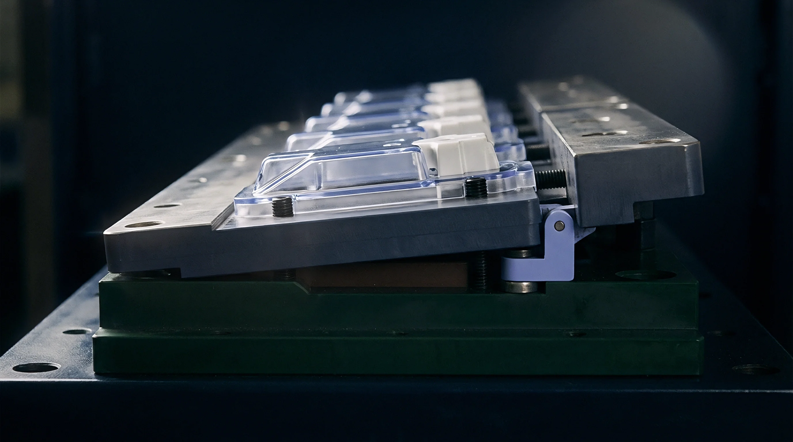
Volumetric Shrinkage Gradients across Cavity Matrices
Specific volume changes during polymer crystallization depend directly on local cooling rates within the mold steel. Higher mold wall temperatures slow the polymer cooling rate, allowing polymer chains additional time to align and crystallize into dense morphology. Dense crystalline regions shrink significantly more than rapidly cooled amorphous zones, altering part dimensions.
When cavity wall temperatures vary across a tool face, parts produced in hotter cavities achieve higher final density and exhibit greater overall volumetric shrinkage.
Variable shrinkage across cavities compromises part interchangeability in precision assemblies. Parts produced in position A1 may comply with nominal CAD models, while identical parts from position D8 fail functional fit checks due to dimensional undersizing caused by localized insert thermal accumulation. Eliminating cavity thermal variations aligns volumetric shrinkage across all cavity streams, narrowing dimensional distribution curves.
Process Window Shift under Thermal Non Equilibrium
A tool operating without stabilized wall temperatures experiences continuous drift in cavity pressure and packing density. Temperature shifts alter local melt viscosity within the cavity. As cavity steel heats up during continuous running, polymer flow resistance drops, allowing injection pressure to transfer further into the cavity end-of-fill zones.
Hotter cavities experience over-packing and flashing, while cooler cavities suffer from under-packing, sink marks, or internal voids.
Thermal stability locks the process window in place across long production shifts. Stabilizing mold steel temperatures ensures that hydraulic holding pressure transfers identically into every cavity, fixing uniform gate seal times and volumetric density across all parts in the shot matrix.
| Mould Temperature Delta-T (°C) | Volumetric Shrinkage Delta (%) | Achievable Tolerance Grade (DIN 16742) | Dimensional Variance on 50mm Feature (mm) | Scrap Rate Impact (%) |
|---|---|---|---|---|
| 1.0 | 0.02 | TG4 (Precision) | ±0.025 | 0.1 |
| 3.0 | 0.06 | TG5 (Standard High-Precision) | ±0.045 | 0.5 |
| 6.0 | 0.14 | TG6 (General Commercial) | ±0.085 | 3.2 |
| 12.0 | 0.32 | TG7 (Coarse Commercial) | ±0.160 | 12.8 |
- Map Cavity Temperature Distribution using radiometric thermography during initial T1 trial runs to identify thermal hot zones across cavity plates.
- Adjust Individual Circuit Flow Restrictors to boost fluid flow rates through hotter internal cavity blocks, restoring uniform surface temperatures.
- Modify Core Pin Cooling Inserts by installing high-conductivity beryllium-copper or amco metal cores in uncooled deep core regions to eliminate localized heat sinks.
- Re-Evaluate Part Dimensions Across Cavity Streams using optical CMM measurement to verify that dimensional variance falls within specified ISO tolerance bands.
Part warpage magnitude correlates directly with localized thermal gradients present across cavity walls during cooling.
It remains undetermined whether real-time mold temperature adjustment can fully counteract viscosity variations introduced by resin lot changes.
Economics
Tooling capital investment correlates directly with cavity count, channel complexity, and thermal control technology. Amortization depends on part volume. Purchasing low-cost tooling with plain gun-drilled cooling circuits reduces initial capital outlay but penalizes production economics through extended cycle times and higher scrap rates caused by thermal non-equilibrium.
High-performance multi-cavity tooling incorporates optimized cooling topologies that minimize cycle times and stabilize cavity-to-cavity quality metrics.
Quantifying the financial return on advanced thermal tooling designs requires balancing upfront tool fabrication costs against long-term machine-hour rates, scrap reductions, and energy consumption per unit manufactured. Thermal equilibrium optimization shortens cycle times while eliminating part quality rejections driven by cavity dimensional drift.
Tooling Amortization and Cycle Time Optimization
Reducing cycle time by two seconds across a multi-cavity production run offsets the initial capital expenditure of complex cooling circuits. Consider a 16-cavity tool producing automotive connector housings running on a 150-tonne press with a machine-hour rate of $65.00 per hour. Conventional straight-drilled cooling lines yield an optimized cycle time of 18.0 seconds, delivering 3,200 parts per hour.
Upgrading the tool design to include additive-manufactured conformal cooling inserts adds $24,000 to the initial tooling build cost.
Conformal cooling channels extract heat evenly across all cavity faces, accelerating part solidification and reducing required cooling time from 9.0 seconds to 4.5 seconds. Total cycle time drops from 18.0 seconds to 13.5 seconds, boosting production output from 3,200 to 4,266 parts per hour. The 25 percent increase in hourly output lowers molding conversion cost from $20.31 per thousand parts to $15.23 per thousand parts, yielding a net savings of $5.08 per thousand components produced.
On a total production contract volume of 6,000,000 parts, cumulative conversion savings total $30,480, fully amortizing the $24,000 conformal tooling premium within the first 4.7 million parts and generating net operational savings over the remaining contract life.

Verification Dossier Clauses for Tool Sign Off
Formal tool qualification frameworks require measurable evidence that cavity wall temperatures remain within defined tolerances during steady-state production. Tool purchase contracts must stipulate thermal equilibrium validation parameters alongside mechanical dimension approvals. Sourcing agreements should require suppliers to submit continuous cavity temperature log data and post-ejection thermographic scans as prerequisite documentation for final tooling milestone sign-off and payment release.
Specifying maximum permissible cavity-to-cavity temperature deltas within tooling RFQs protects buyers against poorly balanced cooling designs. Standard procurement clauses mandate that the supplier demonstrate steady-state cavity wall temperature uniformity within ±2.0°C across all cavitation positions under production cycle conditions before formal hand-off occurs.
The financial payback of high-efficiency thermal layouts resolves into direct machine-hour savings when high-volume tooling runs continuously over multiple shifts.