Cavity Pressure Feedback Protocol for Dynamic Shrinkage Compensation in Automated Multi Cavity Injection Tooling
Dynamic cavity pressure feedback balances volumetric shrinkage across multi-cavity tools by adjusting holding profiles to stabilize real-time melt density.

Dynamics
Pressure Profiles and PVT Transitions in Multi Cavity Tooling
Melt compression in high-cavitation tooling governs local specific volume before thermal solidification fixes final dimensions. Standard machine stroke limits switch pack pressure based on screw position, ignoring thermal variance across separate cavity runners. Pressure transducers installed directly inside individual cavities capture the precise instant polymer reaches full volume packing.
Polymer behavior follows pressure-volume-temperature relationships where localized cooling rates alter the specific volume decay path. When cavity pressure decays too rapidly, volumetric shrinkage increases, generating internal sink or dimensional reduction below print specification.
Viscosity shifts between raw resin lots alter runner flow resistance. A viscosity rise of ten percent shifts the pressure drop along long runner branches, leaving terminal cavities under-packed while gate region pressure spikes. Standard injection profiles maintain constant hydraulic thrust, transferring these rheological variations directly into part mass variation.
Real-time monitoring of cavity peak pressure isolates melt density variations before thermal gates freeze. Transducers positioned near the end of fill detect incomplete packing caused by thermal drift or batch-to-batch polymer lot inconsistency.
Cooling circuits in 16-cavity or 32-cavity frames rarely remove thermal energy symmetrically. Outer cavity inserts often run three to five degrees Celsius warmer than inner core blocks due to manifold heat dissipation. Temperature differentials shift the solidification boundary, altering the time window available for pressure transmission through open gates.
Higher cavity temperatures prolong the molten core state, demanding sustained packing pressure to offset higher intrinsic thermal contraction.
| Cavity Position | Peak Pressure (bar) | Melt Temp (°C) | Volumetric Shrinkage (%) | Linear Dimensions (mm) |
|---|---|---|---|---|
| Near Gate (Cavity 01) | 580 | 232 | 1.42 | 50.02 ± 0.012 |
| Mid Cavity (Cavity 01) | 460 | 228 | 1.68 | 49.95 ± 0.015 |
| End of Fill (Cavity 01) | 340 | 221 | 2.10 | 49.82 ± 0.022 |
| Near Gate (Cavity 16) | 520 | 236 | 1.55 | 49.98 ± 0.014 |
| End of Fill (Cavity 16) | 290 | 223 | 2.35 | 49.74 ± 0.028 |
Volumetric Phase Decay across Asymmetric Mold Geometry
Volumetric change during crystallization dictates final component geometry. Semi-crystalline polymers like polyoxymethylene or polypropylene exhibit abrupt specific volume changes during phase transition. Amorphous polymers like polycarbonate decay along a gradual thermal slope, making pressure transmission less sensitive to millisecond timing errors.
In multi-cavity tooling, gate freeze timing across different cavities determines whether packing pressure maintains part volume or allows melt backflow. Early gate freeze creates under-packed components, leading to loose wall thickness and elevated post-moulding contraction.
Peak cavity pressure targets established during tool qualification lose validity when cooling fluid flow drops below turbulent thresholds.
Balanced runner systems attempt equal fill times across all impression locations. Rheological asymmetry occurs because shear heating heats the polymer flowing into central cavities while outer cavities receive cooler melt. The viscosity differential causes central cavities to pack faster than outer positions.
Dynamic compensation alters the packing pressure intensity per valve gate or adjusts machine holding duration based on cavity integral pressure readings.
Sensor signals trigger valve gate actuators or modulate machine hydraulic pressure to standardize integral pressure curves. Integrating pressure over time yields the pressure-time integral, a value directly proportional to final part density. Matching pressure-time integrals across all cavities normalizes volumetric shrinkage regardless of physical location within the mold matrix.
Thermal sensors combined with pressure pins isolate the exact moment of physical gate seal. Continuous acquisition of peak pressure values yields feed control inputs that automatically stabilize part weights over long production runs.
Whether closed-loop valve gate control can entirely negate volumetric variance caused by localized tool steel thermal expansion remains an open technical boundary in ultra-precision molding.
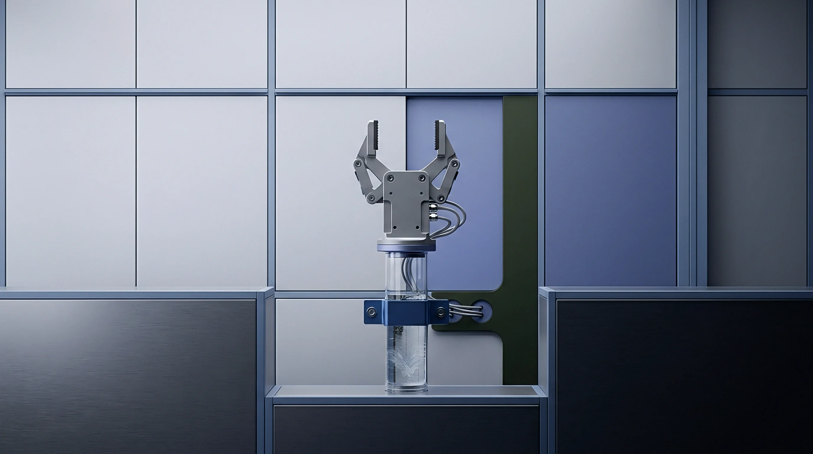

Pin
Piezoelectric Transducer Placement and Load Transfer Dynamics
Sensors installed behind ejector pins convert mechanical force into measurable voltage signals. Quartz crystal elements produce electrical charge proportional to Applied compressive stress. Pin diameter selection directly alters signal strength and surface indentation risk on finished components.
Standard design practices select ejector pins positioned opposite thick wall sections or directly adjacent to gate locations. Force transmission relies on smooth pin movement without mechanical binding in the core plate bore.
Friction along ejector pin sidewalls absorbs force intended for quartz crystal elements. A clearance fit exceeding 0.008 millimeters allows polymer flash to ingress around the pin tip, binding the assembly and skewing sensor readings downwards. Button-style piezoelectric sensors installed behind dummy pins eliminate cosmetic surface marks while shielding sensor surfaces from aggressive melt contact.
Strain gauge sensors present a alternative for cost-sensitive molds, though thermal drift requires continuous zero-point calibration during production start-up.
- Ejector Pin Sensors capture total force via direct contact with cavity melt through a hardened pin interface.
- Direct Cavity Transducers measure fluid pressure via flush-mounted diaphragm faces touching molten polymer directly.
- Button Type Load Cells sit beneath ejector plates to monitor total clamp load distribution across mold core structures.
- Indirect Strain Gauge Transducers mount within steel relief pockets to measure elastic tool deformation under pressure loads.

Signal Amplification and Drift Mitigation across High-Cavitation Tools
Low-charge piezoelectric outputs require immediate charge amplification near the molding machine platen. Cable lengths exceeding three meters collect electrical noise from high-voltage heater bands and servo motor drives. Digital signal conversion within multi-channel junction boxes converts weak charge signals into digital data packets resistant to electro-magnetic interference.
Standard sampling frequencies of 1000 Hertz track steep pressure spikes during velocity-to-pressure switchover phases.
DIN 16742 Grade TG4 tolerances demand real-time hold pressure regulation derived from end-of-fill cavity sensor triggers.
Thermal zero shift affects piezoelectric output when mold temperatures fluctuate. High-heat polymers like polyetheretherketone transmit extreme thermal loads through ejector pins into transducer housings. Sensor cooling channels embedded within core backing plates stabilize transducer temperatures below 120 degrees Celsius.
Software algorithms apply baseline drift compensation by zeroing charge amplifiers while the mold stands open between ejection and lockup cycles.
Suppliers frequently claim that factory calibration factors remain permanent over millions of cycles, despite mechanical wear degrading charge generation efficiency.


Control
Real-Time V/P Switchover Protocol Execution
Switching from speed-controlled filling to pressure-controlled packing traditionally depends on screw position or hydraulic pressure limits. Position-based switchover fails when material viscosity drops, causing mold over-packing and flash. Cavity pressure feedback transfers switchover control directly to melt conditions inside the tool cavity.
When sensor voltage reaches a preset threshold, machine controller logic executes instantaneous transfer to packing mode. Transfer timing occurs within two milliseconds of target pressure detection.
Multi-cavity tools utilize peak cavity pressure signals from the slowest-filling cavity to trigger global machine switchover. Alternatively, individual cavity valve gates close sequentially as each cavity achieves peak target density. Sequential valve gating requires needle valve actuators operated via high-speed pneumatic or electric servo drivers.
Electric servo actuators offer position resolution down to 0.01 millimeters, enabling modulated gate opening rates that suppress pressure spikes during runner opening.
- Melt enters cavity runner systems under high-speed volumetric displacement.
- Primary cavity transducer registers pressure rise indicating nineties percent filling completion.
- Controller switches machine hydraulic circuit to packing control mode instantly.
- Secondary transducers monitor pressure decay rates through gate solidification phase.
- Valve gate pins extend sequentially to isolate cavities reaching target pressure-time integrals.

Closed-Loop Hydraulic and Electric Servo Compensation Algorithms
Modern processing software compares real-time pressure curves against reference curves recorded during initial tool qualification. Deviations in pressure rise slope indicate viscosity shifts or nozzle temperature fluctuations. Adaptive control algorithms adjust hydraulic valve opening widths or electric drive motor currents within the current cycle.
If cavity pressure rises too slowly, hold pressure ramps up by five to fifteen percent to maintain constant specific volume decay.
| Parameter | Analog Sensor Array | Digital Bus System | Direct Servo Valve Gate |
|---|---|---|---|
| Sampling Rate (Hz) | 500 | 2000 | 5000 |
| Response Latency (ms) | 8.5 | 1.2 | 0.4 |
| Switchover Accuracy (bar) | ± 12.0 | ± 2.5 | ± 0.8 |
| Data Bus Protocol | 0-10V Analog | CANopen / EtherCAT | Direct Fieldbus Signal |
Proportional-integral-derivative control loops regulate hold pressure profiles dynamically. Derivative actions suppress pressure overshoot, preventing parting line flash on thin-walled technical components. Integral actions eliminate steady-state pressure errors caused by cooling fluid temperature drift.
Machine controllers store individual cycle profiles to generate statistical process control charts, identifying gradual machine wear before non-conforming dimensions land in final packing boxes.
Specific purchase agreements specify ISO 20457 compliance, requiring automated machine shutoff whenever cavity pressure integrals deviate more than three percent from validated master envelopes.
Tolerance
Dimensional Shrinkage Stack-Up Analysis under Variable Pressure Integrals
Linear part dimensions correlate directly with local volumetric shrinkage rates. Glass-filled polymers exhibit anisotropic shrinkage due to fiber orientation parallel to melt flow paths. Cavity pressure control suppresses transverse shrinkage variation by driving polymer chains tight during early cooling phases.
Holding uniform pressure integrals across all cavities narrows linear dimensional distribution curves across multi-impression tooling frames.
Moulding a 100-millimeter connector housing in thirty percent glass-filled polybutylene terephthalate yields baseline shrinkage of 0.4 percent longitudinal and 1.1 percent transverse. Uncontrolled pressure fluctuations expand transverse shrinkage variation up to 0.35 percent, exceeding tight engineering drawing tolerances. Closed-loop pressure feedback limits transverse shrinkage scatter within 0.08 percent across a 50,000-unit production run.
This precision allows tool designers to specify tighter steel dimensions during initial EDM machining operations.
Tolerance stack-ups include tool machining errors, thermal expansion of mold plates, and process-induced volumetric shifts. Steel machining holds tolerances of ± 0.005 millimeters per impression. Thermal expansion adds ± 0.003 millimeters across a 400-millimeter plate.
Cavity pressure controls reduce process variation from ± 0.040 millimeters down to ± 0.008 millimeters, making precision production feasible without costly secondary machining operations.

Can Cavity Pressure Sensors Standardize Multi Cavity Shrinkage Variance?
Equalizing pressure integrals across dissimilar cavities compensates for physical flow length differences. In family molds producing matching top and bottom housings, volume ratios cause uneven filling rates. Smaller cavities experience early packing while larger cavities continue filling.
Individual cavity pressure control balances density build-up between both impressions, assuring snap-fit alignment upon final assembly.
Shrinkage control efficacy drops when thermal cooling channel fouling restricts heat transfer locally. Pressure feedback compensates for thermal delays by extending hold times, but extended cycle times increase part production cost. Sensor data flags thermal imbalances by displaying delayed pressure dissipation curves, alerting press setters to scale scale buildup inside cooling channels.
A simple rule of thumb states that doubling cavity sensor density cuts dimensional variance in half across large-format tools.


Payout

Tooling Capitalization and Transducer System Infrastructure Expenses
Integrating cavity pressure electronics elevates initial tooling expenditure. Direct piezoelectric transducers cost between 800 and 1,500 USD per channel, including wiring harnesses and mounting hardware. Multi-channel signal amplifiers and integration cards add 10,000 to 25,000 USD per press installation.
A 32-cavity tool requires up to 45,000 USD in sensing hardware alone, raising upfront tool building investment significantly.
Sensors require routine maintenance and recalibration during scheduled tool overhauls. Ejector pin clearance checks prevent pin scoring and sensor face damage. Cable failure caused by mold plate movement represents a recurring operational expense.
Tooling budgets allocate five percent of initial mold cost annually for sensor maintenance, replacement wiring, and connector repairs.

Scrap Reduction Economics and Automated Quality Sorting Systems
Automated sorting gates reject individual non-conforming parts based on cavity pressure trace data. If Cavity 07 registers an incomplete pressure integral during shot 1,420, an electrical signal activates a diverter chute to isolate that single component. Shot isolation prevents scrap contamination of bulk packaging lots, eliminating full-batch sorting costs.
High-speed scrap diverters operate within 50 milliseconds of mold opening cycles.
A worked example demonstrates economic viability on an 8-cavity medical syringe plunger tool running medical grade polypropylene. Assume an hourly press operating rate of 85 USD, a cycle time of 12 seconds, and an annual volume of 15 million units. Standard unmonitored production yields a baseline scrap rate of 2.8 percent due to short shots and sink marks from material lot switches.
Implementing cavity pressure feedback drops scrap rates to 0.3 percent while reducing start-up scrap during tool warm-up phases.
Scrap reduction saves 375,000 parts per year. At a material cost of 0.04 USD per part and machine time value of 0.03 USD per part, total annual direct savings reach 26,250 USD. Adding automated part rejection avoids manual sorting labor valued at 18,000 USD annually.
Total return recovers the 32,000 USD sensor installation cost within 8.6 months of continuous operation.
Omitting real-time pressure tracking on high-cavitation medical tools leaves part quality vulnerable to unrecorded material viscosity shifts, risking lot rejections and contract default penalties.