Dynamic Cavity Pressure Strain Calibration for Multi Cavity Micro Tooling
Dynamic strain calibration matches indirect pin force signals to true cavity pressure transients across micro cavities to eliminate fill imbalance.
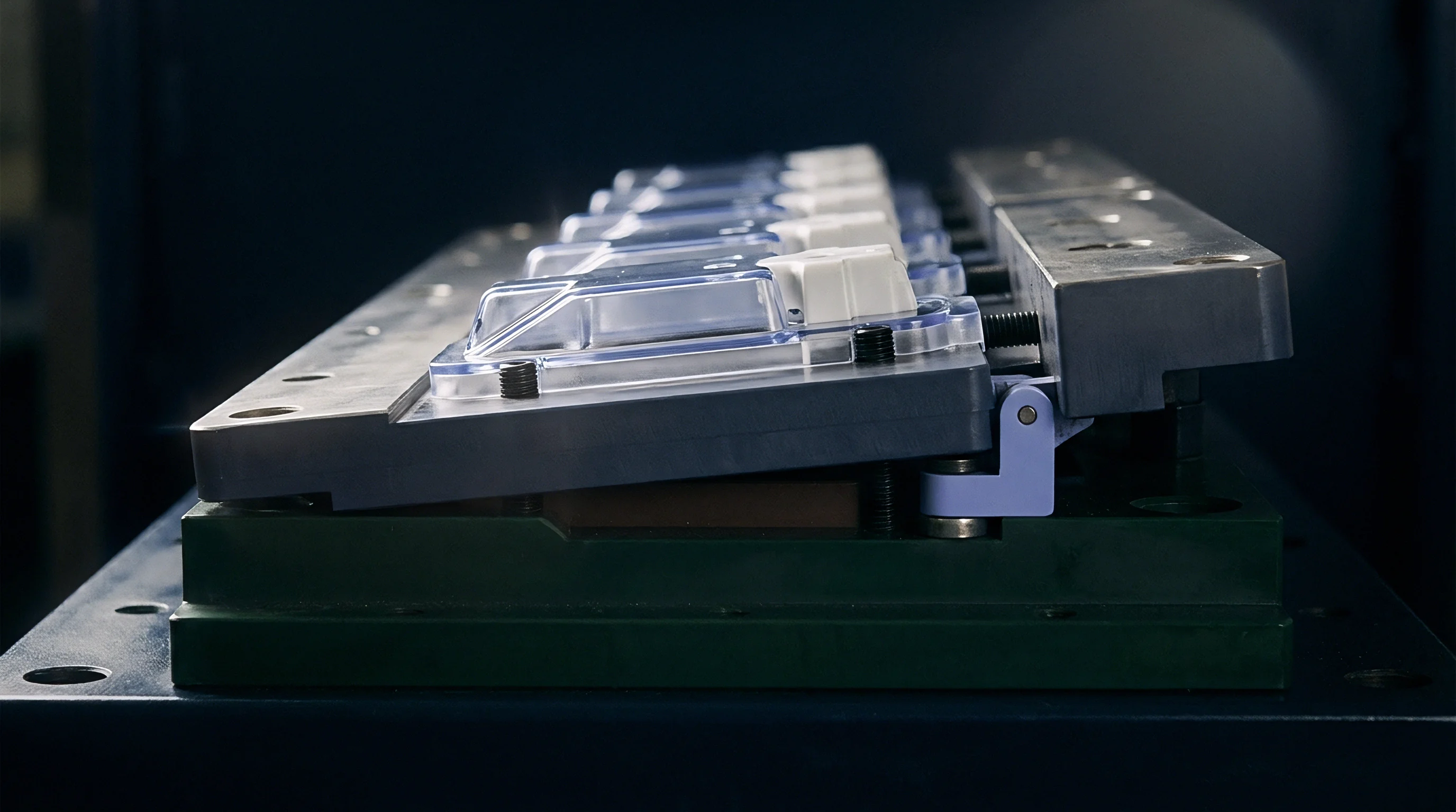

Probe
When micro-molded parts weigh under five milligrams and wall sections drop below 150 micrometers, direct diaphragm pressure sensors cannot enter the cavity layout without leaving witness marks or cutting into local cooling channels. Instead, piezoelectric or piezoresistive strain elements sit behind active tooling pins to translate melt-fill forces into electrical charge. That transfer depends heavily on the mating face between the pin base and the sensor button: any surface roughness beyond 0.2 micrometers Ra causes non-linear force attenuation.
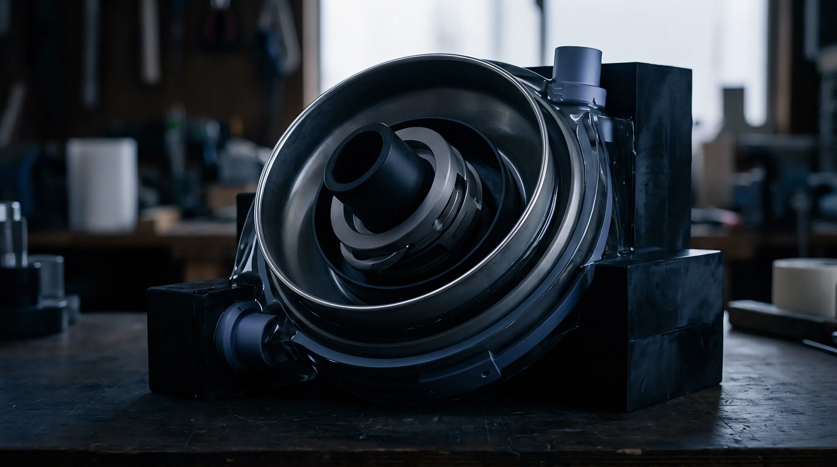
Indirect Transducer Placement in Micro Cavity Inserts
In tooling plates housing sixteen or thirty-two micro cavities, tight spacing usually forces the strain elements down into sub-plates beneath the ejector assembly. Positioning a transducer 15 millimeters behind the parting line introduces measurable lag as the intervening steel pin compresses. Under a 1200 bar cavity pressure, an 0.8-millimeter tool steel pin deforms elastically as a column, blunting the peak strain rate recorded at the sensor face relative to the true melt front impact.
Peak melt pressure recorded behind a micro ejector shaft reads up to 14 percent lower than true cavity front pressure when local pin friction exceeds 18 Newtons.
Melt entry drives micro-tooling components at high axial velocities, sending elastic waves through the surrounding support steel. Shifting from direct cavity contact to pin-backed sensing drops the assembly’s natural frequency from 120 kilohertz to under 15 kilohertz, which rounds off the sharp pressure spikes that define the handover from filling to packing.
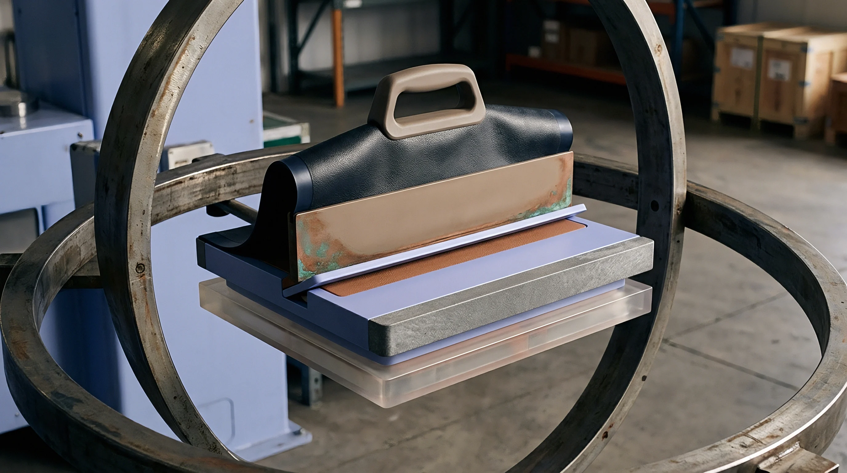
Pin-Based Force Transfer Dynamics
Hydraulic pressure transfers through these slender shafts only as cleanly as guide bore clearances permit. Standard tolerances between 2 and 4 micrometers invite melt ingress and flash with low-viscosity grades like liquid crystal polymers or polyoxymethylene, wedging the pin during high-pressure hold phases.
- Pin Bind Jamming Sets in when thermal expansion tightens guide clearance below one micrometer, generating artificial strain signals that suggest cavity pressure remains high well after the part ejects.
- Piezo Drift Skew Stems from continuous heat transfer down the slender ejector shaft, gradually drifting the electrical baseline across extended runs.
- Friction Force Offset Arises when bore contact absorbs as much as 25 percent of cavity force, under-loading the transducer element beneath.
Any misalignment in the sensor pocket converts axial load into bending moments across the transducer diaphragm, ruining factory bench calibrations and feeding false data into active machine controls.
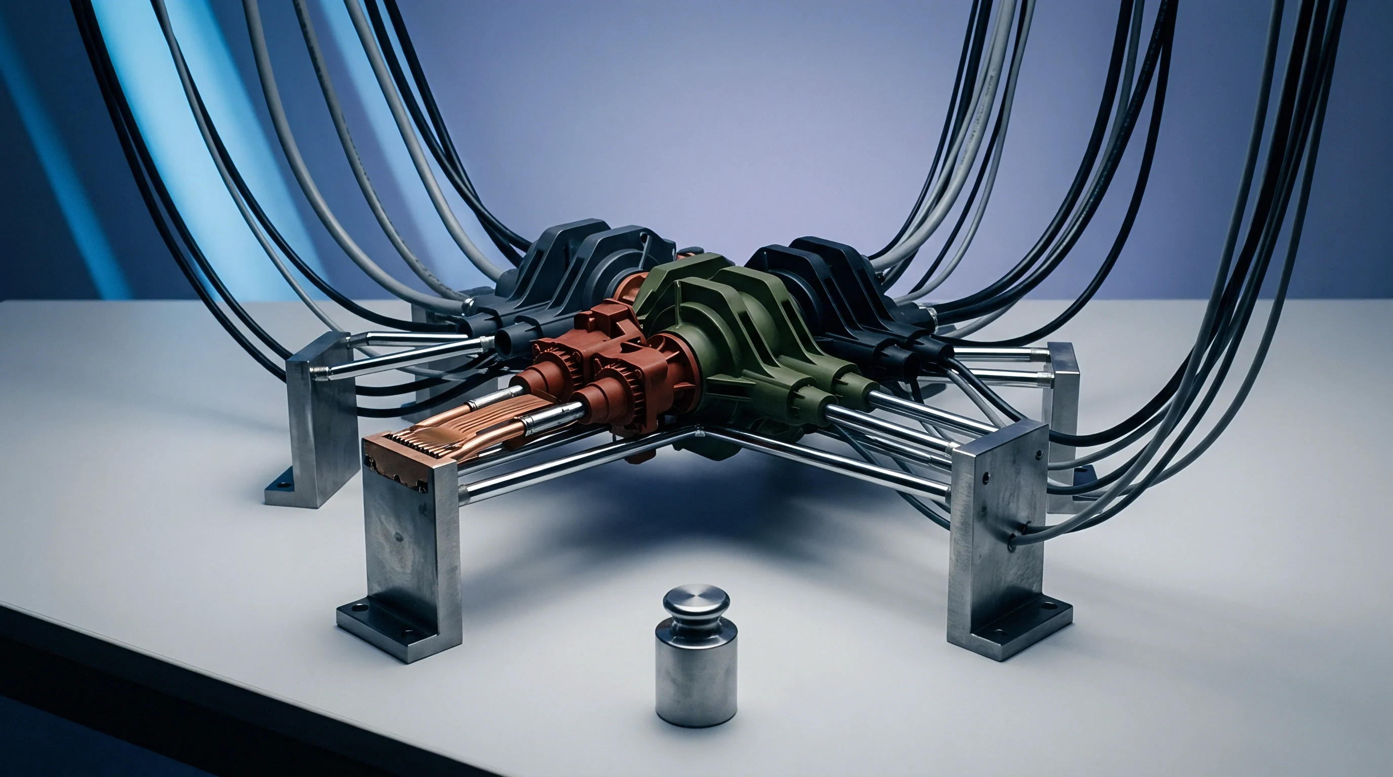
Hysteresis
Cavity loading curves rarely match the release curve recorded as the polymer cools and pulls back from the mold walls. Sidewall friction along the ejector pin siphons off force during filling, then delays the pin’s return as the part solidifies, stretching the pressure-time trace into a broad hysteresis loop. That mechanical lag blurs the actual gate seal point, so optimizing cycles directly from raw strain signals requires dynamic mathematical filtering.

Frictional Losses along Micro Ejector Shafts
Sliding friction along the micro insert bore changes constantly with mold temperature and lubricant breakdown. Above 1500 bar, lateral cavity pressures flex slender ejector shafts against the hardened guide walls, driving friction up sharply. Because this loss scales inversely with shaft diameter, an 0.5 millimeter pin loses twice as much signal fidelity as a 1.5 millimeter pin.
| Transducer Configuration | Sensing Diameter (mm) | Signal Delay (ms) | Frictional Loss (%) | Thermal Sensitivity (%/10 K) |
|---|---|---|---|---|
| Direct Piezoelectric Cavity Pin | 1.00 | 0.05 | 0.00 | 0.12 |
| Indirect Ejector Pin Strain Gauge | 0.80 | 1.40 | 12.50 | 0.85 |
| Indirect Ejector Pin Piezo Transducer | 0.50 | 2.10 | 18.20 | 1.10 |
| Cavity Wall Structural Strain Foil | N/A | 0.80 | 0.00 | 2.30 |
Viscosity variations aggravate shaft drag by forcing melt into the guide clearances. As polymer films build up along the bore, static stiction increases ahead of each ejection stroke, nudging the baseline sensor signal upward shot after shot.
Thermal Expansion and Zero Point Drift
Thermal gradients across multi-cavity core plates set up uneven expansion throughout the mold steel. As the tool heats from 25 degrees Celsius at cold startup to a running equilibrium of 90 degrees Celsius, expanding ejector pins exert a static preload on the transducers. Unless the acquisition software zeroes out baseline drift between cycles, thermal growth registers on the monitor as false cavity pressure.
Thermal expansion in constrained tooling steel generates fictitious pressure offsets when baseline signals reset incorrectly before mold clamping completes.
Inconsistent cavity pressure readings are frequently attributed to resin batch variation, although mechanical binding inside sub-plate sensor pockets is the underlying problem.

Signal
Turning raw voltages from indirect strain sensors into usable pressure data requires acquisition rates above two kilohertz per channel. When injection units fill micro cavities in under 30 milliseconds, the analog-to-digital hardware must sample fast enough to resolve peak pressure before the gate freezes. At the same time, signal conditioning needs to filter out the high-frequency ringing of mold clamp impact without damping the pressure rise when melt hits the wall.
Dynamic Injection Pressure Response Mapping
Benchtop hydraulic presses cannot duplicate the thermal and mechanical realities of an active molding cycle. Dynamic calibration instead injects a metered pulse of target resin directly into the runner, comparing pin strain against reference transducers seated in runner junction blocks. The resulting transfer matrix compensates for pin flexure, thermal growth, and signal damping across the tool’s operating window.
- Preheat tool plates to stable operating temperature for two hours under active oil circulation.
- Purge injection barrel with target resin and establish stable dosing volume across ten air shots.
- Inject calibration melt charges into sealed dummy runners equipped with high-speed reference transducers.
- Record simultaneous strain and reference pressure waveforms at a minimum sampling frequency of five kilohertz.
- Calculate polynomial transfer functions relating peak strain voltage to peak hydraulic cavity pressure.
- Verify calibration coefficients by injecting test specimens across three distinct injection speed settings.
These calculated transfer coefficients translate millivolt outputs into bar values for each cavity independently, absorbing local machining variances. Conditioning amplifiers then trim gain settings based on where each cavity sits in the runner branch.
Multi Cavity Sensor Acquisition Protocols
Monitoring multi-cavity micro tools requires simultaneous data capture across all positions to catch filling imbalances. Processors track the peak pressure derivative for each cavity to flag hesitant flow from runner variation or gate wear, while isolated wiring channels prevent cross-talk across high-impedance piezoelectric leads packed into the wireways.
Per ISO 20457 guidelines, dimensional tolerances on micro-molded parts correlate directly with peak cavity pressure stability across consecutive manufacturing lots.
In-line processing strips out tool deflections by subtracting signals from auxiliary reference gauges mounted directly on the mold frame.
Balanced strain traces across all channels confirm that the cavities are filling at identical volumetric rates.
Compliance
Injecting high-viscosity resins through sub-millimeter gates forces substantial deflection through the mold plates. Because center cavities flex more than perimeter positions, initial sensor preload shifts during packing. Compliance in the support pillars and cavity retainers absorbs force that would otherwise reach the pin sensors, shifting the sensitivity curve from one cavity to the next.
Insert Deflection and Plate Flexure Analysis
Finite element models show micro cavity inserts deflecting elastically by several micrometers under 1800 bar cavity pressure. This flexure drops the zero reference on underlying sensors, producing false negative pressure readings right at packing transition. To limit this background deflection, rigid tool designs rely on hardened backup plates rated above 58 HRC.
| Cavity Location | Peak Pressure (bar) | Plate Flexure (µm) | Raw Strain (mV/V) | Calibrated Pressure Error (%) |
|---|---|---|---|---|
| Inner Cavity 01 | 1450 | 3.80 | 1.42 | + 6.20 |
| Inner Cavity 02 | 1445 | 3.75 | 1.41 | + 5.80 |
| Outer Cavity 07 | 1380 | 1.20 | 1.28 | – 2.10 |
| Outer Cavity 08 | 1375 | 1.15 | 1.27 | – 2.40 |
Plate flexure reduces the mechanical force reaching perimeter sensors relative to center positions. Compensating for this gradient requires setting cavity-specific calibration offsets under actual clamping force.
Deploying dynamic strain calibration requires meeting the tooling acceptance criteria laid out in standard supply agreements.
- Plate Stiffness Verification Confirms mold plate deflection remains below 0.005 millimeters under a full 50-ton machine clamping load.
- Zero Balance Trimming Requires electronic baseline zeroing once the mold reaches thermal equilibrium, clearing static preload.
- Thermal Soak Equilibrate Mandates at least two hours of continuous thermal conditioning before running production strain calibrations.
Under standard commercial purchase agreements, any tool showing cavity-to-cavity pressure variation wider than five percent must be pulled for vendor-funded rework.
Amortization
Instrumenting a micro mold with dynamic cavity pressure sensors raises initial tooling costs by 15 to 25 percent depending on cavity count. Transducers, sub-plate pockets, high-temperature wiring, and multichannel acquisition racks represent a noticeable upfront investment. That outlay pays back through lower scrap rates, shorter cycle times, and automated sorting during unmanned runs.
Sensor Durability and Capital Replacement Metrics
Micro ejector pins backing these sensors see millions of rapid load cycles, eventually wearing or fatiguing. Factoring sensor replacement into tooling budgets as routine maintenance keeps it from skewing operational overhead unexpectedly. Bonded piezoresistive foil gauges cost less up front than quartz piezoelectric sensors, but degrade sooner under persistent thermal cycling.
Scrap reduction remains the primary justification for full instrumentation. In a 32-cavity mold running medical connectors on a 2.5-second cycle, production exceeds 45,000 parts per hour. Catching a short shot or blocked gate within two cycles prevents thousands of bad parts from reaching downstream assembly.
On high-volume micro-molding lines, integrated strain calibration typically repays its tooling premium within 180 operating shifts. Rejecting parts automatically against calibrated cavity pressure boundaries avoids the labor expense of off-line inspection.
What signal drift limit should mandate full sensor recalibration across extended runs reaching into millions of cycles?