Wireless Cavity Pressure Telemetry for Closed Loop Process Control
Wireless cavity pressure telemetry enables real-time closed-loop V/P switchover, preventing flash and sink marks without wiring inside moving tool plates.


Quartz
A 15-millimeter ejector pin backed by a piezoelectric charge transducer registers peak contact stress within 4 milliseconds of polymer arriving at the gate. As the melt front advances, it compresses the steel pin, driving force directly into synthesized crystalline slices cut along the electrical axis. Surface charges build in direct proportion to mechanical load, generating a picocoulomb-level signal tied to internal cavity hydraulics.
Converting this deflection into a usable voltage requires high-impedance signal conditioning placed within millimeters of the sensor. Direct pressure sensors rest flush against the cavity wall and touch molten resin at temperatures up to 380 degrees Celsius, whereas indirect layouts place the sensing element behind a standard ejector pin, where temperatures stay below 150 degrees Celsius.
Piezoresistive strain gauges offer a different path, using silicon elements bonded to a flexing diaphragm. As the diaphragm deflects under melt pressure, electrical resistance changes across a Wheatstone bridge circuit, producing a millivolt output that needs less insulation shielding than high-impedance piezoelectric lines. Because piezoresistive components suffer no charge leakage during long holding phases, they work well in thick-walled structural mouldings with packing times over 45 seconds.
Quartz sensors, by contrast, hold their structural stiffness up to 500 degrees Celsius without calibration drift, making them the default option in precision tools running high-temperature resins such as polyetheretherketone or polyphenylene sulfide.
Sensor dimensions control spatial resolution and placement options inside the core or cavity steel. Direct sensors with diaphragm diameters down to 1.0 millimeter fit narrow ribs or runner channels, catching localized viscosity shifts near thin walls. Indirect sensors depend heavily on pin diameter and fit tolerances.
If an ejector pin fits too loosely, polymer flash creeps into the bore, binding the pin and deadening force transfer. Clearances above 0.008 millimeters let resin enter when moulding unfilled polyamide 66, truncating the force peak and creating artificial pressure hysteresis.

Physical Transduction Mechanics
Converting mechanical force accurately depends on maintaining electrical isolation across the crystal lattice. Contamination, moisture, or resin outgassing around the sensor housing creates a low-resistance path that leads to charge leakage and baseline drift. Insulation resistance across piezoelectric terminals must stay above 10 to the 12th power ohms throughout operation.
Indirect setups buffer against thermal shock by placing the sensor housing inside the cooler ejector plate assembly, using a hardened tool steel pin to block heat flow. Mechanical pre-loading holds the sensor tight against its seat, keeping force transmission linear from the first millibar of melt pressure.
Precise force measurement relies on pre-load bolts tightened to specified torque values, establishing zero-point stability before resin enters the impression. Incorrect torque shifts the sensitivity curve, causing a 100-bar miscalibration across the process window.
| Transducer Type | Direct Piezoelectric | Indirect Piezoelectric | Piezoresistive Diaphragm |
|---|---|---|---|
| Contact Medium | Molten Polymer | Ejector Pin Base | Diaphragm Surface |
| Operating Temperature Range | Up to 400 °C | Up to 200 °C | Up to 200 °C |
| Signal Output Type | Charge (pC) | Charge (pC) | Voltage (mV) |
| Response Time | Less than 1.0 ms | 1.0 to 3.0 ms | 2.0 to 5.0 ms |
| Low-Frequency Limit | 0.01 Hz (Quasi-static) | 0.01 Hz (Quasi-static) | 0.00 Hz (Static) |
| Maximum Pressure Rating | 2500 bar | 2500 bar | 2000 bar |
Choosing an indirect configuration means matching pin stiffness against cavity deflection under clamp load. Heavy, oversized pins add inertial lag during fast injection phases above 300 millimeters per second. Undersized pins flex under uneven flow fronts, jamming in the tool plate and sending false pressure drops to the node.
Direct sensors require polishing flush with the cavity contour within 0.005 millimeters: a protruding sensor leaves marks on cosmetic surfaces, while a recessed face forms a stagnant pocket where degraded resin builds up over long runs. Ignoring thermal expansion differences between tool steel and sensor bodies risks crushing the housing or losing pre-load during heat cycles, cutting off telemetry mid-shift.


Link
Removing physical wiring from the tool base eliminates the main failure point in multi-cavity moulds. Cables threaded through moving ejector plates flex constantly, causing copper fatigue, torn insulation, and short circuits against grounded steel. Wireless telemetry transmitters mount directly in the mold frame, digitizing charge signals into radio frequency or inductive pulses.
Protocols operating at 2.4 GHz or sub-GHz bands broadcast through non-metallic tool cutouts or exit via waveports machined into the steel. Antenna placement controls signal stability: mounting an omnidirectional antenna flush with the outer mold plate keeps RF paths clear of machine platens and tie bars.
Battery and power management set the working life of transmitters in hot tools. High-density lithium thionyl chloride batteries can power up to two million machine cycles when paired with low-duty sleep modes. Thermoelectric generators provide another option, drawing from the temperature difference between hot mold plates and cooling channels via the Seebeck effect to run battery-free nodes.
Passive inductive coupling presents a third option, using a reader coil on the machine platen to energize an internal mold coil across an air gap while the tool is closed, sending power and data together without internal batteries.
Signal Propagation through Steel Tooling
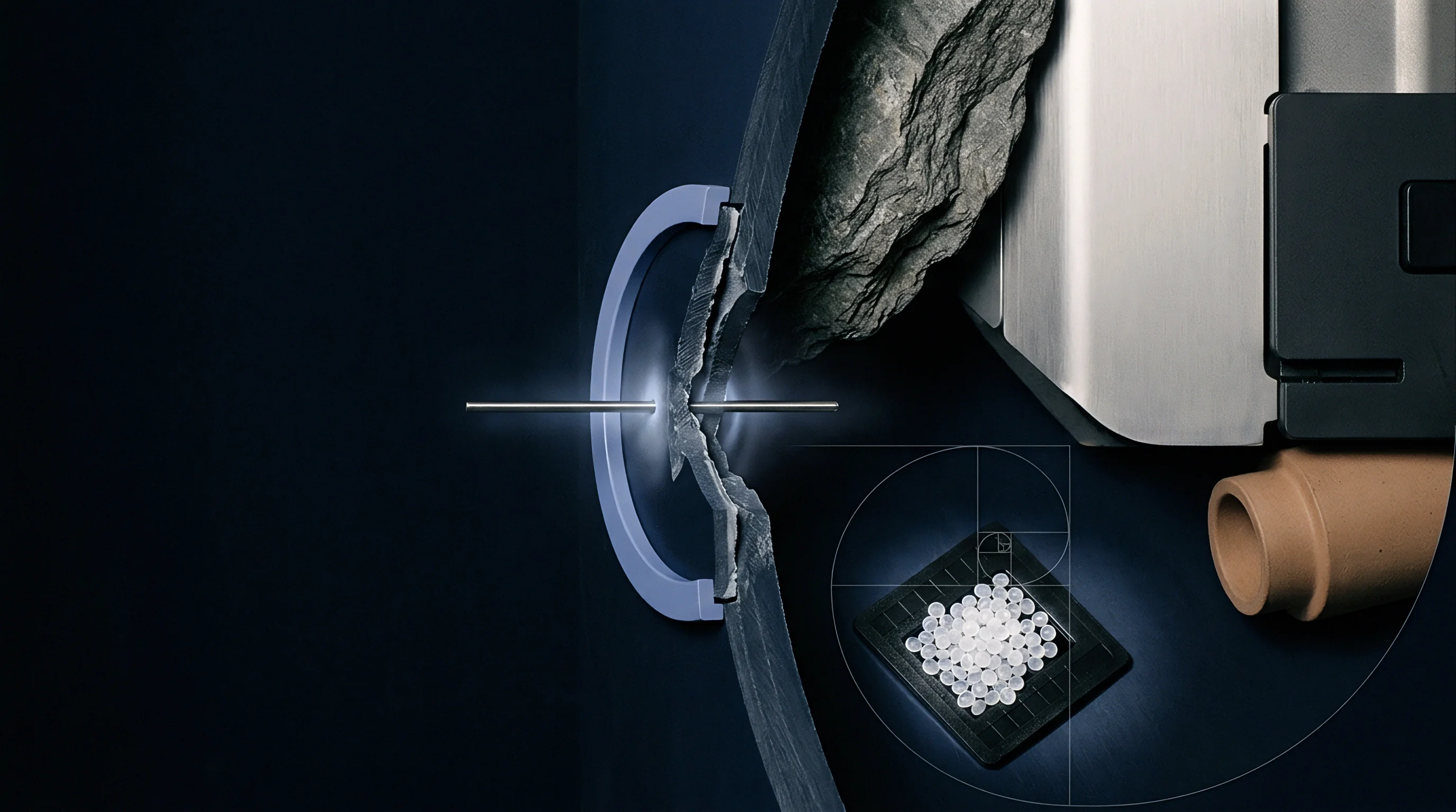
Getting radio signals through solid tool steel requires intentional electromagnetic paths. Solid H13 steel blocks high-frequency signals entirely, trapping them inside internal pockets unless dedicated exit routes are machined. Slot antennas in the outer mold plates act as RF windows, sealed with radio-transparent polyetheretherketone inserts to block oil and shop debris.
Sub-GHz bands like 868 MHz or 915 MHz bend around tie bars far better than 2.4 GHz signals, preserving connections in busy press rooms.
RF telemetry bypasses mechanical slide interfaces entirely, preventing crushed wire harnesses and cable breakage during complex core-pull sequences.
Piezoelectric cavity sensors linked through 2.4 GHz industrial telemetry experience attenuation exceeding 18 decibels when surrounded by steel tool plates thicker than 45 millimeters without dedicated signal release channels.
Sealing keeps hydraulic fluids, mold cleaners, and anti-rust sprays away from internal transmitter electronics. Enclosures made of anodized aluminum or stainless steel rely on fluoroelastomer O-rings rated for continuous use at 150 degrees Celsius. Thermal insulation shields digital microcontrollers from heat radiated by hot runner manifolds, keeping internal node temperatures inside the safe silicon operating limit below 85 degrees Celsius.
- Metallic Attenuation Dense carbon and alloy tool steels block electromagnetic radiation entirely, requiring strategic antenna placements near tool parting lines.
- Platen Shielding Solid cast-iron machine platens reflect RF signals, creating multi-path interference patterns that demand spatial antenna diversity at the machine receiver.
- Thermal Degradation Elevated mold frame temperatures reduce lithium battery discharge efficiency and accelerate self-discharge rates, cutting active node life in half for every 10-degree rise above ambient limits.
- Dielectric Interference Coolant channels filled with water-glycol mixtures absorb microwave energy, requiring antenna paths isolated from active temperature control circuits.
Signal dropouts often stem from internal antenna detuning caused by shifting mold plates during clamping, rather than external factory radio frequency pollution. When receiver modules miss data packets during injection, manuals frequently suggest raising RF transmission power instead of addressing impedance mismatches caused by condensation building up inside the antenna pocket.


Response
Closed-loop process control works only if pressure telemetry is processed quickly enough to trigger machine actions within millisecond windows. Standard switchover from velocity filling to pressure packing depends on screw position or hydraulic line pressure. Cavity pressure telemetry measures resin behavior inside the mold impression directly, bypassing melt compressibility, check-valve leakage, and barrel thermal drift.
Triggering switchover from cavity pressure peaks or threshold values stops screw forward movement the moment the cavity fills, preventing flash on thin-walled precision parts.
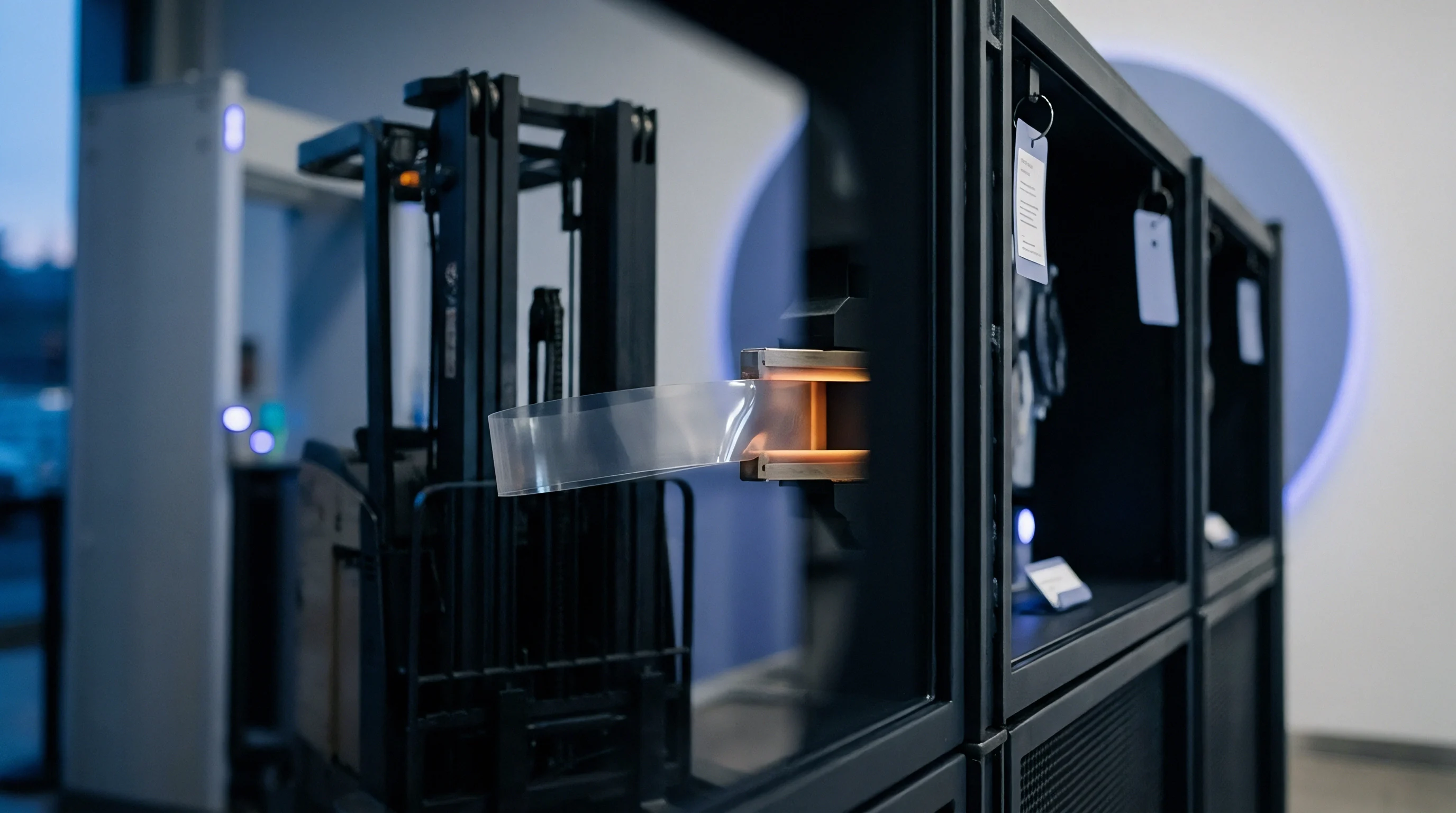
Data transmission latency sets the accuracy of closed-loop control. A telemetry system that takes 15 milliseconds to digitize, transmit, decode, and hand off a threshold signal lets the injection screw advance several millimeters past the ideal switchover point. At injection speeds of 200 millimeters per second, a 10-millisecond lag means 2.0 millimeters of screw over-travel, packing extra resin into the cavity and driving peak pressure up by as much as 250 bar.
Modern industrial nodes use high-speed analog-to-digital converters and low-latency wireless protocols to keep total loop response under 2.0 milliseconds.
How Does Telemetry Signal Latency Impact Hydraulic Switchover Timing?
Delays in signal processing directly degrade dimensional consistency. Once the wireless receiver decodes a cavity pressure packet, it communicates with the press controller through fieldbus networks like Real-Time Ethernet, EtherCAT, or POWERLINK. Hydraulic valves take another 5 to 12 milliseconds to shift position after receiving the command.
Accounting for this total loop latency allows engineers to set dynamic switchover thresholds that anticipate valve delays, holding peak cavity pressure within a plus-or-minus 5 bar window across thousands of shots.
Because hydraulic pressure lags the melt front, machine nozzle pressure readings overstate actual cavity pressure during dynamic fill due to shear-thinning pressure drops across sprues, runners, and narrow gates.
Compliance with EUROMAP 77 interface specifications binds machine controllers to process closed-loop pressure telemetry within a 2-millisecond determinism window or drop automatically into open-loop velocity control.
Real-time PID loops adjust holding pressure based on constant cavity feedback. Rather than applying a fixed hydraulic holding pressure, the controller shifts ram force dynamically to track a target pressure decay curve as the melt cools and the gate freezes. This active adjustment offsets batch-to-batch viscosity variations driven by regrind content or raw material moisture changes.
| Process Stage | Physical Action / Subsystem | Typical Latency Range | Impact on Screw Position at 200 mm/s |
|---|---|---|---|
| Transduction | Quartz charge generation and pre-amp conversion | 0.05 – 0.20 ms | 0.01 – 0.04 mm |
| Digitization | Transmitter ADC sampling and packet filtering | 0.20 – 0.50 ms | 0.04 – 0.10 mm |
| RF Transmission | Wireless packet packaging and transmission | 0.50 – 1.20 ms | 0.10 – 0.24 mm |
| Fieldbus Interface | Receiver decoding and EtherCAT transmission | 0.20 – 0.80 ms | 0.04 – 0.16 mm |
| Machine Controller | PLC interrupt processing and command output | 0.50 – 1.50 ms | 0.10 – 0.30 mm |
| Hydraulics / Servo | Servo valve spool displacement and oil shift | 3.00 – 8.00 ms | 0.60 – 1.60 mm |
Integrating wireless telemetry into commercial injection machinery requires explicit specifications in the purchase contract. Machine supply agreements adhering to ISO 20457 dimensional tolerance standards incorporate dynamic control clauses specifying that cavity pressure closed-loop response latency must remain under 3.0 milliseconds total loop time, failing which the machine builder bears financial responsibility for fitting hardwired high-speed analog overrides.

Variance
Process drift in a multi-cavity tool shows up as gradual changes in the shape of pressure profiles over time. Thermal expansion in hot runner nozzles, progressive vent clogging, and wear on gate inserts alter how melt enters individual cavities. Continuous telemetry records these shifts shot by shot, tracking pressure integrals, peak timing, and cooling decay rates.
Comparing active pressure traces against a known baseline catches mold fouling before non-conforming parts show up during final inspection.
As melt temperature rises and viscosity drops, polymer flow resistance shifts peak cavity pressures even when screw injection speed stays constant.
Cavity pressure peak drift across a multi-cavity mould signals thermal imbalance in the hot runner nozzles long before dimensional deviation appears on finished parts.
Viscosity shifts are the single largest cause of shot-to-shot variation in commercial moulding. Recycled resins, color concentrates, and changes in ambient humidity continuously alter the polymer melt flow index during a run. Cavity pressure feedback absorbs these material shifts by automatically extending or shortening the velocity phase, maintaining volumetric filling regardless of batch consistency.
For critical dimensions, process capability indices such as Cpk jump from 1.12 to over 1.67 when switching from machine-position switchover to cavity-pressure control.
- Short Shots Premature gate freezing or viscosity spikes drop cavity peak pressure below threshold levels, triggering immediate automated part sorting gates on the automated conveyor belt.
- Part Flash Excessively high cavity pressure integrals indicate over-packing, signaling potential parting line flash and tool damage risk before the clamp opens.
- Sink Marks Insufficient packing pressure duration permits internal melt shrinkage away from cavity walls, caught by analyzing pressure decay slopes prior to gate seal off.
- Vicious Weld Lines Sub-optimal melt front convergence pressures cause structural weakness along knit lines, flagged when cavity sensors fail to hit minimum pressure thresholds during initial cavity pressurization.
Comparing pressure traces across cavities pinpoints imbalance issues in large mold frames. In an 8-cavity medical tool, a single lagging curve flags a restricted gate, a blocked cooling channel, or a failed heater band on a hot runner tip. Real-time telemetry identifies the problem cavity immediately, letting robotic end-of-arm tooling reject parts from that location while the remaining seven cavities keep running.
Engineers continue to debate whether closed-loop cavity pressure control can fully offset wall thickness changes caused by mold plate thermal expansion during long production runs. While pressure-controlled packing keeps core density uniform, heat growth expands the steel cavity itself. This leaves open whether mould temperature control must link directly to cavity pressure algorithms to hold sub-10-micron tolerances across seasonal ambient temperature shifts.

Economics
Justifying investment in wireless cavity pressure telemetry comes down to tool maintenance, scrap reduction, and downtime numbers. Hardwired sensors generate high repair bills from pinched cables, oxidized connectors, and broken wiring harnesses inside slide mechanisms. A single pinched wire in an 32-cavity mold can trigger hours of teardown, consuming technician time and stopping production.
Removing internal wiring cuts assembly labor and protects electrical components from hydraulic fluid.
Scrap reduction forms the core of the financial argument. Automated closed-loop control catches short shots and flash immediately, keeping bad parts out of downstream assembly. In automotive and medical moulding ~ where defect penalties carry heavy financial risk ~ zero-defect strategies rely on cavity telemetry tied to individual part serial numbers for full traceability.
Wireless sensor retrofits eliminate signal cable fatigue failures at slide parting lines, shifting maintenance effort from wiring harness replacement to lithium battery lifecycle tracking.
Retrofitting existing tools requires minimal steel modification. Machining external pockets for radio transmitters leaves core and cavity inserts untouched, preserving the tool’s structural integrity. Standardizing node dimensions across molds makes receiver hardware interchangeable between presses, lowering the cost of upgrading legacy tooling to scientific moulding practices.
| Cost Component | Hardwired Sensor Setup | Wireless Telemetry System | Economic Variance Analysis |
|---|---|---|---|
| Initial Hardware Investment | Low ($2,200 per mold) | Moderate ($4,800 per mold) | Wireless carries $2,600 initial hardware premium |
| Tool Machining & Wiring Wiring Labor | High ($3,500 labor) | Low ($1,200 labor) | Wireless saves $2,300 in toolroom wire routing steel cuts |
| Pinch Wire Repair & Maintenance | $1,800 per 250k cycles | $0 (No internal wires) | Wireless saves $7,200 in maintenance across tool life |
| Unplanned Tool Downtime Costs | 24 hours total ($7,200) | 2 hours total ($600) | Wireless saves $6,600 in lost press capacity |
| Scrap Reduction Savings | 1.5% average scrap rate | 0.2% average scrap rate | Wireless yields $18,200 savings in saved resin and press time |
| Net Commercial Value Position | Baseline Operational Cost | Net Savings: $28,700 | Full payback achieved within 240,000 production shots |
Calculating the return on investment for wireless telemetry relies on scrap rates, repair records, and machine hour costs.
- Audit historical repair records for hardwired tools to calculate wire harness failure frequencies and associated press downtime expenses per machine shift.
- Determine the landed resin and machine-hour cost of scrap produced during initial warm-up phases and mid-run process drift events.
- Quantify the labor cost associated with manual part inspection routines that automated cavity pressure limit gates replace.
- Calculate the total conversion expenditure, combining wireless transmitter hardware, receiver base stations, and pocket machining quotes.
- Divide total conversion expenditure by the cumulative monthly cost savings derived from downtime elimination and scrap reduction to yield the exact payback timeline in active production months.
As a rule of thumb, any tool running expensive engineering resins with cycle times over 30 seconds pays back the wireless telemetry system well before its first major overhaul.