Viscoplastic Strain Rate Sensitivity Optimization for Short Glass Reinforced Components
Dynamic viscoplastic yield in short glass components depends on screw-retained fiber length and gate-driven orientation tensors under high strain rates.

Yield
Dynamic Plasticity under Ballistic and Impact Rates
Short glass fibers embedded in semicrystalline polyamides alter matrix deformation kinetics under rapid loading. At quasi-static rates of 0.001 per second, neat polyamide 66 yields near 80 megapascals at room temperature with 50 percent relative humidity. Introducing 30 percent short glass fibers by weight elevates this threshold to 175 megapascals along the principal flow direction.
Increasing the strain rate to 100 per second shifts the yield point beyond 240 megapascals. The polymeric chains experience restricted reptation time under rapid displacement, forcing higher stress states before the onset of permanent shear banding. Viscoplastic models capture this phenomenon by coupling rate-independent plastic criteria with viscous overstress formulations.
Perzyna viscoplastic representations express the plastic strain rate through an overstress function scaled by a viscosity parameter and a rate sensitivity exponent. In filled polymers, the effective stress driving viscoplastic slip depends heavily on local fiber orientation. When fibers align with the tensile axis, the stiff inclusions shield the surrounding polymer matrix from shear deformation, deferring yield.
Transverse alignment channels shear stresses directly into the matrix ligaments between adjacent glass filaments, lowering the rate-dependent yield transition by 35 to 45 percent. An accurate structural prediction depends on mapping injection-induced fiber orientation tensors directly onto the non-linear constitutive equations.
At 120 per second strain rate and 23 degrees Celsius, dry PA66-GF30 yields at 255 megapascals along the primary orientation axis.
Experimental validation of rate-dependent yield behavior demands split-Hopkinson pressure bar apparatus and high-speed servo-hydraulic test frames running according to ISO 18872. Standard quasi-static tensile curves produce catastrophic under-prediction of component stiffness during crash events. Structural brackets sized solely from ISO 527 data deform far less than predicted during collision pulses, transferring excessive kinetic energy to adjacent metal assemblies.

Viscoplastic Hardening Formulation Parameters
Constitutive modelling platforms implement Johnson-Cook and Cowper-Symonds equations to modify the dynamic yield stress across decades of strain rate. The Cowper-Symonds model scales the static yield stress using two empirical constants: a structural transition rate parameter and a power-law exponent. For short glass reinforced polybutylene terephthalate with 30 percent glass content, the transition parameter clusters around 420 per second, accompanied by a sensitivity exponent of 0.32.
Glass-reinforced polypropylene exhibits a much steeper rate dependence, with sensitivity exponents frequently exceeding 0.45 due to the pronounced viscous damping of the polyolefin backbone.
Fiber breakage and debonding compete with matrix plasticity as the deformation rate climbs. High strain rates suppress the plastic dissipation zone at the fiber ends, promoting interfacial decohesion and sudden micro-cracking. Ignoring the interaction between viscous flow and localized fiber pull-out creates severe discrepancies between simulated crush tube responses and physical drop-tower impacts.

Gate

Filling Velocity Dictates Core Morphology
Melt delivery paths govern the spatial distribution of glass fibers through kinematic shear and extensional fields. As the polymer-fiber suspension enters the cavity through a restrictive gate, shear rates exceed 20,000 reciprocal seconds, creating a pronounced skin-shell-core morphology. Near the cold tool walls, rapid thermal quenching freezes a thin, nearly isotropic skin layer.
Just beneath this boundary, high shear gradients align the short glass fibers parallel to the flow vectors, creating a highly anisotropic shell layer. In the central core, extensional deceleration and low shear allow the fibers to orient transverse to the primary melt progression.
High injection velocities expand the shell layer thickness relative to the transverse core. Running a 3.0-millimeter wall plaque with a fast 0.8-second filling time produces a shell that occupies 70 percent of the total cross-section. Reducing injection speed to a 3.5-second fill allows thermal conduction from the cavity steel to chill the melt prematurely, broadening the randomly oriented or transverse core to nearly 50 percent of the wall thickness.
Because dynamic yield stress tracks fiber alignment directly, an aggressive injection speed increases the component’s dynamic axial yield strength while diminishing its through-thickness energy absorption.
Wall thickness determines cooling rate while injection speed fixes shell proportion across the part section.
Direct gating into thin structural ribs generates severe fiber orientation divergence. Fan gates spread the advancing melt front uniformly, minimizing the orientation gradients that cause differential viscoplastic yielding across wide chassis components. Pin gates create radial fountain flow, yielding concentric rings of varying strain rate sensitivity that complicate finite element mesh mapping.
Why Does Gate Position Dictate Crash Failure?
Weld lines formed by meeting flow fronts display virtually zero fiber continuity across the interface. Short glass fibers align parallel to the converging fronts, leaving only an unreinforced polymer matrix bridge across the seam. Under quasi-static loading, this seam exhibits a knock-down factor of 0.50 to 0.65 relative to nominal bulk strength.
Under impact rates exceeding 50 per second, the matrix cannot relax local stress concentrations, and the joint fails via brittle cleavage at less than 30 percent of the base material yield point. Position gates so that converging fronts wash into non-structural clamp bosses or low-stress perimeter flash pockets.
Submarine gates shearing across ejector pins reduce manual degating expense, yet their tight orifices cause severe glass fiber breakage. Screw recovery and gate shear jointly degrade average fiber length from 250 micrometers in the virgin pellet down to 110 micrometers in the molded part cavity. Shorter fibers reduce the critical aspect ratio necessary for efficient shear transfer, blunting the strain rate enhancement factor of the composite.
Edge gates with generous land lengths protect aspect ratio, securing the predicted dynamic yield strength at the cost of a secondary trimming operation.
Uniform nominal wall design preserves the integrity of fiber aspect ratios across complex geometries. Sudden cross-sectional expansions induce re-circulation vortices that tumble fibers into disordered clumps, destroying orientation predictability.
Rupture
Strain Rate Dependent Damage Limits
Failure in short glass reinforced thermoplastics switches mode as load application velocity increases. At low deformation velocities of 1 millimeter per minute, matrix yielding accommodates localized shear around fiber tips, allowing diffuse void coalescence before crack propagation. When loading velocity increases to 10 meters per second, local adiabatic heating combines with suppressed chain disentanglement to force brittle micro-cracking along fiber-matrix interfaces.
The macroscopic failure strain drops dramatically. For a 30 percent glass-filled polyphthalamide, elongation at break falls from 2.8 percent under quasi-static tension to 1.1 percent at impact strain rates above 80 per second.
Triaxiality functions define the locus of rupture under multiaxial impact. Structural components rarely experience pure uniaxial tension during functional service. Combined shear, bending, and membrane loads generate high hydrostatic tension fields, particularly behind stiffening ribs and mounting lugs.
High stress triaxiality suppresses matrix shearing, accelerating interfacial decohesion and triggering catastrophic component shattering at nominal strains far below uniaxial test bar limits.
| Polymer Matrix and Glass Content | Strain Rate (1/s) | Yield Stress (MPa) | Elongation at Break (%) | Elastic Modulus (GPa) |
|---|---|---|---|---|
| PA66-GF30 Dry | 0.01 | 175 | 3.1 | 9.5 |
| PA66-GF30 Dry | 1.0 | 205 | 2.4 | 10.8 |
| PA66-GF30 Dry | 100.0 | 255 | 1.4 | 12.6 |
| PBT-GF30 Dry | 0.01 | 135 | 2.8 | 9.0 |
| PBT-GF30 Dry | 1.0 | 158 | 2.1 | 10.2 |
| PBT-GF30 Dry | 100.0 | 192 | 1.2 | 11.9 |
| PP-GF30 Chemically Coupled | 0.01 | 92 | 3.8 | 6.2 |
| PP-GF30 Chemically Coupled | 1.0 | 118 | 2.9 | 7.1 |
| PP-GF30 Chemically Coupled | 100.0 | 152 | 1.6 | 8.5 |
Energy absorption calculation requires integrating the area beneath dynamic true stress-strain curves up to the point of material rupture. While yield stress rises with strain rate, the concurrent collapse of ultimate elongation frequently reduces total energy dissipated prior to final fracture. Sizing structural crash absorbers around elevated dynamic yield values without compensating for lower ductility results in premature shattering during crash test validation.
Constitutive Characterization Protocols
Mapping dynamic behavior into crash solvers like LS-DYNA or PAM-CRASH demands specialized material cards. Standard isotropic formulations such as MAT_024 fail to represent the directional variance inherent to glass-filled injection molded structures. Advanced orthotropic viscoplastic models like MAT_157 or micromechanical solvers like Digimat couple local Advani-Tucker second-order orientation tensors with dynamic Tsai-Wu or Puck failure envelopes.
Generating these material cards involves testing injection-molded specimens harvested along specific angles relative to the melt flow direction. Specimens milled at 0 degrees, 45 degrees, and 90 degrees provide the necessary inputs to calibrate anisotropic hill parameters and anisotropic rate multipliers. The experimental campaign must evaluate specimens across at least four decades of strain rate to verify stability in numerical integration schemes.
- Plaque Extraction isolates tensile dogbone coupons from the center of plaque geometries to eliminate boundary edge effects.
- High-Speed Photogrammetry tracks true strain fields using stereo digital image correlation cameras capturing at over 100,000 frames per second.
- Load Signal Filtering applies class 1000 hardware and software filters to remove mechanical test bench ringing caused by high-frequency stress waves.
- Tensor Mapping transfers predicted cavity orientation data directly onto structural mesh nodes via solid volume discretization.
Purchase contracts specifying automotive impact components must cite DIN EN ISO 18872 test compliance to hold suppliers liable for structural dynamic shatter.
Material testing tolerances established under DIN EN ISO 18872 define limits for load cell inertia correction and specimen damping during high-rate events. Compliance with these criteria prevents artificial stress oscillations from being mistaken for physical material yield transitions, establishing reliable simulation baselines.

Window

Barrel Temperature and Fiber Length Retention
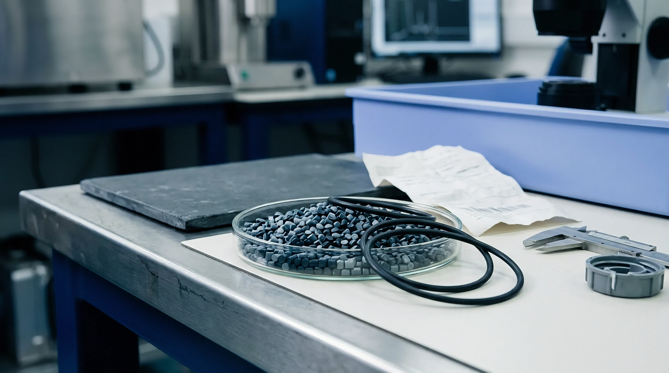
Screw recovery conditions in the injection moulding press govern the physical integrity of the short glass reinforcement before the melt ever reaches the runner. Glass fibers enter the feed zone as concentrated rovings cut to roughly 3.0 millimeters in length within the masterbatch pellet. Excessive screw backpressure and aggressive rotational speed generate intense shear within the transition zone, grinding filaments against each other and against the nitrided barrel walls.
Fiber breakage accelerates dramatically when melt temperatures fall below the optimal polymer processing window, as heightened resin viscosity increases hydrodynamic drag on the rigid filaments.
Maintaining melt temperature toward the upper third of the resin manufacturer specification reduces matrix viscosity and protects fiber length. For an unconditioned 30 percent glass reinforced PA66, setting the nozzle zone to 295 degrees Celsius preserves an average part fiber length of 230 micrometers. Dropping that barrel zone to 270 degrees Celsius raises viscosity, grinding the average fiber length down to 140 micrometers.
This attrition truncates the dynamic yield stress enhancement at high strain rates, leaving the final molded component vulnerable to unexpected impact failure.
| Melt Temperature (C) | Injection Speed (mm/s) | Backpressure (bar) | Mean Fiber Length (um) | Dynamic Yield at 100/s (MPa) |
|---|---|---|---|---|
| 270 | 40 | 80 | 140 | 218 |
| 270 | 120 | 80 | 115 | 198 |
| 295 | 40 | 30 | 245 | 262 |
| 295 | 120 | 30 | 210 | 248 |
| 310 | 40 | 20 | 250 | 255 |
Thermal degradation of the matrix represents the opposite boundary condition. Holding high-temperature resin in the barrel across extended cycle pauses cleaves the polymer chains, slashing matrix molecular weight. The lower molecular weight matrix exhibits diminished interfacial shear strength, causing glass fibers to pull out freely during rapid dynamic deformation rather than carrying load.

How Does Packing Pressure Alter Rate Response?
Holding pressure compacts polymer chains during volumetric contraction, directly influencing matrix crystallization kinetics. In semicrystalline matrices like polyamide and polybutylene terephthalate, higher packing pressures promote higher core crystallinity levels. Spherulite density within the matrix directly alters viscoplastic slip resistance.
A component packed at 400 bar displays a lower rate sensitivity exponent than an identical component packed at 900 bar, because dense crystalline lamellae constrain amorphous chain mobility, stiffening the baseline matrix response prior to dynamic loading.
Cushion stability monitors consistency across the production shift. A drifting cushion indicates check-ring leakage or inconsistent melt decompression, causing shot-to-shot packing pressure variance. When cavity pressure traces reveal a drop during the packing phase, internal volumetric shrinkage produces micro-voids between adjacent glass fibers.
These internal stress concentrators initiate premature dynamic shear banding during impact events, causing parts to shatter well below quoted dynamic yield ratings.
- Hydraulic Backpressure must remain below 40 bar during recovery to prevent filament fracture inside the screw flights.
- Screw Peripheral Speed should not exceed 0.2 meters per second when compounding abrasive glass-filled resins.
- Cavity Pressure Sensors installed behind ejector pins establish closed-loop switchover control from velocity to pressure stages.
- Mold Surface Temperatures maintained at 90 degrees Celsius ensure uniform crystal growth across outer component layers.
Moulders frequently dismiss scrap rate shifts during seasonal temperature transitions as simple resin lot variations. The resin supplier often points toward ambient factory humidity or drying discrepancies whenever high-speed tensile drop benchmarks fail on production parts.


Ledger
Cavitation Economics and Tool Steel Wear
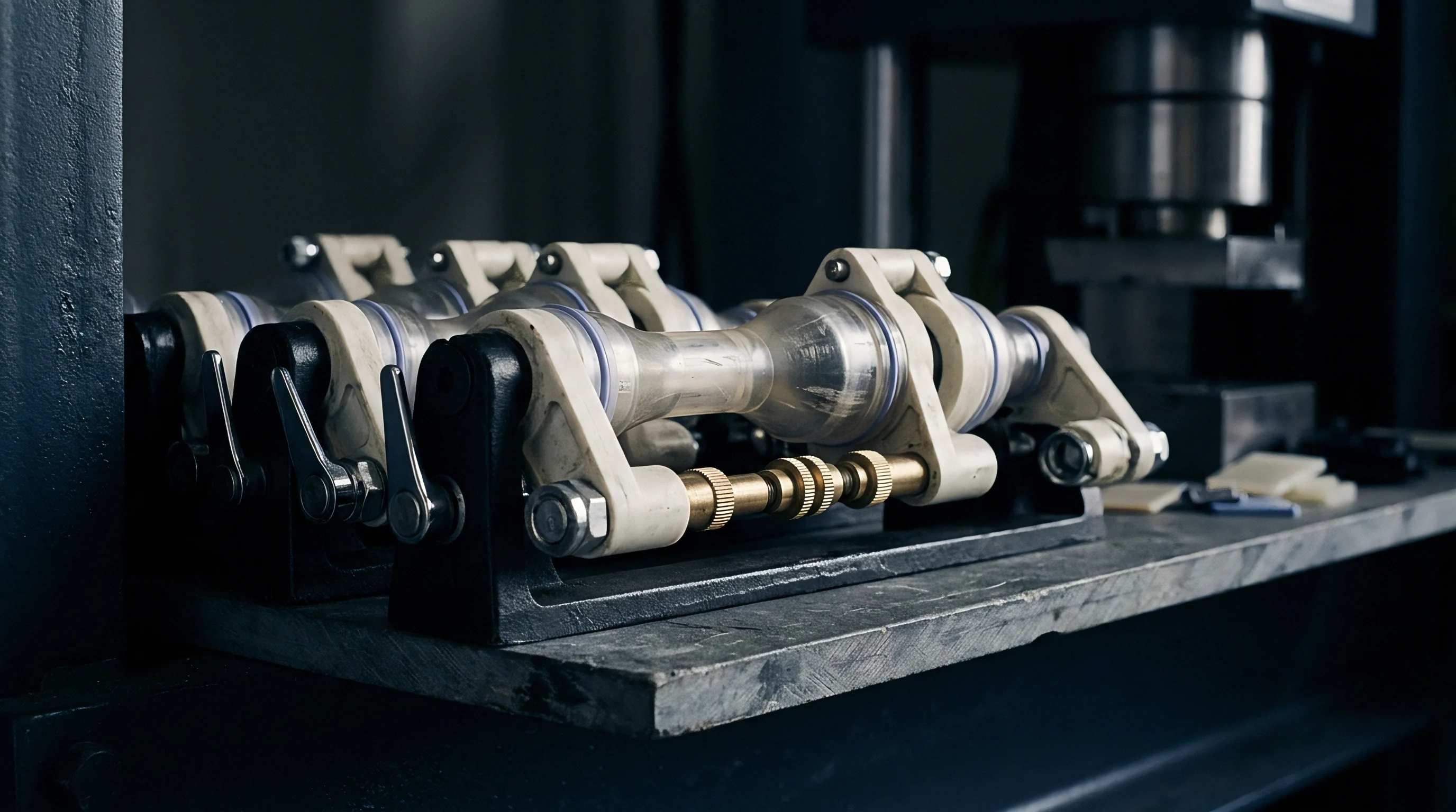
Abrasive wear from short glass reinforcement dictates mold steel selection and maintenance budgets. Standard P20 tool steel cavities erode within 75,000 shots when processing 30 percent glass compounds under high injection velocities, washing out sharp radii and altering gate cross-sections. Widened gates reduce local shear rates, modifying core-to-shell thickness ratios and shifting dynamic strain rate sensitivity across long production runs.
Sourcing practices must specify through-hardened 1.2343 (AISI H13) heat-treated to 52 Rockwell C or premium powder metallurgy grades like Vanadis 4 Extra for sliding cores and high-velocity gate inserts.
Cavitation decisions involve trade-offs between tooling investment, cycle duration, and orientation stability. Increasing cavitation from four to sixteen cavities lowers unit piece price by distributing press-hour charges across more parts per clamp cycle. Multi-cavity runner systems, however, introduce filling imbalances.
Melt entering distant cavities experiences higher shear heating and different fiber breakage patterns than melt filling central cavities. This variance produces a 15 percent spread in dynamic yield strength between parts produced in the same clamp stroke.
| Parameter and Cost Center | Two-Cavity Prototype Tool | Four-Cavity Production Tool | Eight-Cavity High-Volume Tool |
|---|---|---|---|
| Mold Steel Specification | 1.2311 Pre-hardened | 1.2343 ESR (52 HRC) | Vanadis 4 PM Inserts |
| Tooling Investment (USD) | 38,000 | 85,000 | 165,000 |
| Tool Life Expectancy (Shots) | 100,000 | 500,000 | 1,500,000 |
| Cycle Time (Seconds) | 28.5 | 31.0 | 34.5 |
| Press Clamping Force (Tons) | 120 | 220 | 400 |
| Hourly Machine Rate (USD/hr) | 55.00 | 82.00 | 125.00 |
| Part Piece Price at 500k Run (USD) | 1.82 | 1.38 | 1.18 |
Cycle times expand when managing thick-walled glass-reinforced components destined for dynamic structural service. Pulling parts out of the tool before the core crystallizes completely causes uncontrolled post-mold warpage and alters residual internal stress distributions. Residual compressive surface stresses elevate apparent dynamic yield strength, while internal tensile stresses lower impact resistance.
Quenching tools too quickly to compress cycle times locks in unpredictable viscoplastic rate responses that defy numerical simulation.
Production contracts should tie dimensional verification under DIN 16742 directly to drop-tower dynamic impact benchmarks. If tooling wear widens critical rib bases by 0.15 millimeters over 200,000 cycles, the local thermal history changes, altering both fiber orientation and dynamic crash response. What remains unresolved is whether localized optical fiber orientation mapping can be integrated into high-speed inline vision systems quickly enough to reject parts with degraded dynamic yield properties before they ship to assembly lines.