Tool Steel Hardness Specifications for Short Run Injection Moulding
Prehardened 28 to 34 HRC tool steel delivers 50,000 cycles for non-abrasive resins, bypassing heat treatment while securing parting line integrity.


Grade
Short production cycles between 2,500 and 50,000 mouldings depend on selecting tool steels that eliminate secondary heat treatment without surrendering dimensional stability. Specifying prehardened grades between 28 and 34 Rockwell C (HRC) bypasses vacuum furnace cycles, quench distortion, and finish grinding steps. The baseline metal for general injection cavities running unfilled polyolefins or styrene polymers remains modified AISI P20 (1.2311 or 1.2312), supplied quenched and tempered to 280-325 Brinell (HBW).
For higher polish targets or aggressive injection press cycles, European standard 1.2738 adds 1% nickel, promoting uniform cross-sectional through-hardness up to 400 millimetres in block thickness.
When the part volume drops below 5,000 units and uses non-abrasive resins like polypropylene or low-density polyethylene, aircraft-grade aluminium alloys like QC-10 or Alumec 89 supply sufficient mechanical properties at 150-165 HBW. Stepping up to 20,000 shots in abrasive polyamides demands higher surface toughness. Toolmakers then move from base P20 to high-hardness prehardened variants such as Hardox 400 or NAK80, which sits at 37-43 HRC through precipitation hardening.
NAK80 machines cleanly despite its elevated density, accepts high SPI A-2 diamond finishes, and resists parting line collapse under moderate tonnage.
Running 30 percent glass-filled polybutylene terephthalate against 30 HRC steel erodes the gate aperture by 0.12 millimetres within 8,000 press cycles.
Steel selection settles cavity life. Tooling buyers occasionally default to fully hardened H13 (1.2344) or 420 stainless steel (1.2083) tempered to 48-52 HRC out of habit, which inflates machining times by 60 percent and doubles lead times. Through-hardened steels belong in multi-cavity runs exceeding 250,000 shots or tools running halogenated flame retardants that generate corrosive off-gassing.
For runs capped under 50,000 parts, paying for vacuum hardening creates unnecessary financial exposure.
| Material Designation | Hardness Range (HRC) | Yield Strength (MPa) | Thermal Conductivity (W/m·K) | Maximum Recommended Shot Volume |
|---|---|---|---|---|
| Alumec 89 / QC-10 | 15-18 (Converted) | 550 | 160 | 5,000 |
| AISI 1045 / C45D | 16-20 | 350 | 50 | 10,000 |
| AISI P20 / 1.2311 | 28-32 | 850 | 34 | 30,000 |
| 1.2738 (P20+Ni) | 30-34 | 900 | 33 | 50,000 |
| NAK80 | 37-43 | 1100 | 41 | 75,000 |
| AISI 420 Prehard / 1.2085 | 28-33 | 800 | 20 | 40,000 |
| AISI H13 / 1.2344 (Quenched) | 48-52 | 1500 | 25 | 500,000+ |

P20 Chemistry and Prehardened Cavity Blocks
Chromium-molybdenum alloying gives the standard P20 matrix its balance of machinability and impact resistance. Carbon content sits between 0.35% and 0.45%, paired with 1.40% to 2.00% chromium and 0.30% to 0.55% molybdenum. This chemistry avoids the extreme carbide segregation found in high-wear cold work steels like D2.
Machining centres cut the stock in its delivered tempered state, eliminating post-machining heat treatment risks such as unpredicted shrinkage or angular twist across long shutoff faces.
When the mould specification cites 1.2312, added sulfur (0.06% to 0.10%) elevates machinability on standard three-axis vertical mills. The sulfur binds with manganese into manganese sulfide inclusions that act as internal chip-breakers. Those same inclusions compromise mirror polishing and drop photo-etch grain definition below SPI A-3 levels.
For cosmetic A-surface parts, the engineering drawing specifies 1.2738 or vacuum-degassed P20 variants, keeping sulfur below 0.010% to prevent micro-pitting during optical lapping.
Distributors frequently claim that prehardened stock ships uniformly at 32 HRC across the entire billet, yet heavy cross-sections exhibit soft central cores dropping as low as 24 HRC when quenching media fail to chill the deep mass evenly.


Crush
Mechanical stress on injection mould faces concentrates along the parting line land areas. A standard 150-tonne electric or hydraulic press transfers its entire locking force onto relief lands surrounding the component silhouette. When moulders set clamp tonnage without verifying the projected contact area, parting surfaces crush.
Unhardened or soft steel yields under compression, raising burrs and depressing shutoffs, which generates unacceptable flash across the mouldings.
Soft blocks yield under pressure. The projected contact area of a small tool might cover only 12,000 square millimetres. Delivering 1,500 kilonewtons of clamping force across that surface area generates an average compressive stress of 125 megapascals.
While well within the 850 MPa yield strength of 30 HRC steel, uneven clamp distribution, misaligned ejector return pins, or thermal expansion imbalances can double local load. If the contact stress exceeds the compressive yield point, the metal deforms plastically.
Parting surfaces below 30 HRC crush when clamping force exceeds eighty percent of rated press tonnage across relieved lands.
Flash appears across the parting plane. Flash maintenance on a soft tool requires welding or surface re-machining, costing shop hours and halting production. When specifying steels for short runs, calculating minimum land area prevents premature compression failures.

Parting Line Stress and Injection Clamping Tonnage
Balancing the clamp load protects delicate core geometry from crushing. Tool builders grind primary contact lands 0.03 millimetres higher than the secondary mold base plate, isolating the clamping tonnage around the cavity perimeters. If a tool utilizes 30 HRC steel on both halves, galling occurs when sliding side-actions or angle pins rub against cavity walls without adequate differential hardness.
Clamping loads squash fine shutoffs. Slides and lifters need a hardness spread of at least 2 to 4 HRC relative to the cavity core to prevent micro-welding during lockup. When short runs dictate P20 for the core block, builders typically drop bronze wear plates or nitrided inserts behind moving slides.
Surface gas nitriding hardens P20 sliding surfaces up to 60 HRC to a depth of 0.10 millimetres, preventing scuffing without requiring a full furnace quench.
- Interlocking taper locks seat the cavity and core precisely before the main parting faces touch, preventing sliding wear along vertical shutoff steps.
- Relieved perimeter lands leave three-quarters of the mould base cleared by 0.5 millimetres, focusing mechanical clamping loads strictly around part margins.
- Hardened support pillars absorb central deflection behind cavity inserts, preventing the tool from bowing under cyclic injection pressures reaching 140 megapascals.
- Guided ejector plates keep knockout pins aligned perfectly parallel with the pull direction, preventing hole ovalization in softer prehardened steel plates.

Abrasive Fillers and Localized Surface Deterioration
Polymer choice dictates steel life far more aggressively than shot count. Virgin polyethylene runs 50,000 parts through a 28 HRC cavity without measurable gate wear. Adding 30% short glass fibres or calcium carbonate filler turns the flowing melt into a slurry that strips steel atoms from gate edges and flow deflectors within 3,000 cycles.
Glass fibres grind through soft steel. High shear rates at submarine or pinpoint gates generate localized frictional heating, accelerating abrasive wear. The gate land widens, gate vestige grows, and part de-gating tears the moulded skin.
Unchecked abrasion rounds sharp shutoff corners, letting pressurized polymer enter the venting system and clogging escape channels.
Selecting soft alloys for reinforced engineering resins results in parting line flash, dimensional rejection within the first run, and ruined cavity shutoffs that cannot be re-machined without cutting new inserts.

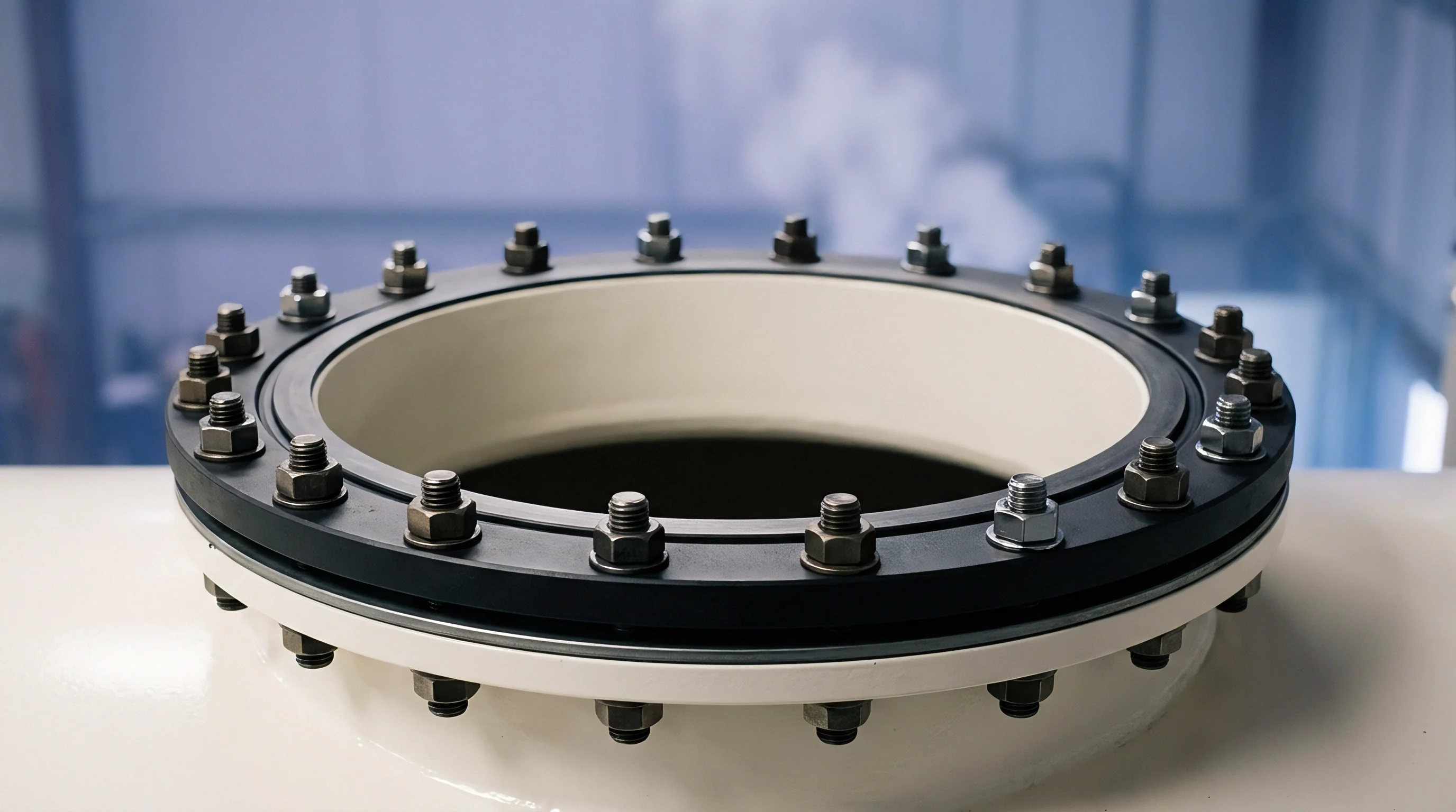
Cut
Machining economics define the viability of short-run tooling. Steel hardness directly controls cutting feed rates, tool deflection, and electrical discharge machining (EDM) wear rates. Solid carbide end mills working 30 HRC prehardened blocks remove material at three times the volumetric rate achievable on 50 HRC hardened H13.
This discrepancy reduces CNC spindle hours, lowering the initial tool invoice for lower production volumes.
Hardness slows chip formation. Modern high-speed machining (HSM) setups process P20 cleanly using solid carbide cutters with aluminium titanium nitride (AlTiN) coatings. The cutter geometry slices through the matrix without sparking, generating controllable chip curls.
Pushing spindle speeds to 12,000 RPM on semi-hardened blocks produces surface finishes approaching Ra 0.4 micrometres directly off the cutter path, eliminating coarse hand-stoning steps.
Thin cuts preserve core details. Micro-milling ribs and tall bosses requires small diameter tools susceptible to breakage when stock hardness fluctuates. Consistent hardness ensures steady cutter loads, preventing tool chatter and dimensional drift across deep pockets.

High Speed Milling in Semi Hardened Tooling
Feed rates and depths of cut change drastically once hardness climbs beyond 35 HRC. Cutting 30 HRC 1.2311 permits a surface speed of 180 to 220 metres per minute. Working through-hardened 1.2344 at 52 HRC limits cutting speeds to 70 to 90 metres per minute while accelerating cutter edge chipping by a factor of four.
The extra machine time adds direct cost to short-run projects that never amortize the expense over high part numbers.
High speed machining also allows toolmakers to cut parting lines and shutoffs directly to net dimensions. Eliminating secondary heat treatment prevents the warping that plagues thin-bladed core features. When components feature deep shutoffs with drafts under one degree, cutting the steel in its final hardened state secures absolute positional tolerance between core and cavity halves.

Electrical Discharge Machining and White Layer Remediation
Deep ribs, sharp internal corners, and textured sidewalls frequently demand sinker EDM using graphite or copper electrodes. The spark erosion process vaporizes steel, leaving behind a brittle, re-solidified surface zone known as the recast or white layer. This layer contains un-tempered martensite riddled with microcracks, reaching hardness levels exceeding 60 HRC regardless of base stock hardness.
Microcracks propagate under cyclic injection loads. When EDM finishes remain unaddressed, tensile stresses during injection open the microcracks into full parting line fractures. Removing the recast layer requires diamond stoning, chemical etching, or orbital polishing before putting the tool in a press.
- Roughing burns with low frequency and high amperage rapidly erode deep cavities, leaving an extensive recast skin up to 0.05 millimetres thick.
- Finishing burns with high-frequency micro-pulses melt smaller surface volumes, reducing the white layer thickness down to 0.005 millimetres.
- Manual stoning using progressively finer aluminium oxide abrasive stones cuts away the hardened crust down to virgin parent metal.
- Glass bead blasting or chemical polishing relieves localized residual surface tensions, sealing the substrate against thermal cracking.
Polishing prehardened steel requires lighter pressure than hardened steel to prevent orange peel effects.


Outlay
Balancing capital expense against piece-part price governs tooling strategies for short run manufacturing. A single-cavity aluminium mould can cost 6,000 dollars, delivering parts at 2.40 dollars each. A hardened multi-cavity H13 tool might cost 32,000 dollars, dropping piece price to 0.85 dollars.
At a production requirement of 10,000 units, the aluminium or prehardened P20 solution yields lower total project expenditures despite a slightly higher cycle time.
Tooling cost amortized across five thousand shots represents seventy percent of the total piece invoice.
Part volume dictates tooling amortization. Prehardened steels provide a safe middle ground. They cost roughly 20 percent more than aluminium stock but offer double the service life and simpler modification options.
Toolmakers can weld P20 using standard TIG equipment directly on the bench without pre-heating the entire block to 400 degrees Celsius, allowing engineering revisions during functional part testing.
| Tool Construction Material | Delivered Tool Cost (USD) | Cycle Time (Seconds) | Part Piece Price (USD) | Total Production Spend (USD) |
|---|---|---|---|---|
| Aluminium 7075-T6 (Single Cavity) | 7,500 | 18 | 1.85 | 26,000 |
| AISI P20 Prehard (Single Cavity) | 9,800 | 22 | 1.95 | 29,300 |
| 1.2738 Prehard (Two Cavity) | 15,200 | 21 | 1.25 | 27,700 |
| AISI H13 Hardened (Two Cavity) | 24,000 | 19 | 1.15 | 35,500 |
| H13 Hardened (Four Cavity) | 38,000 | 17 | 0.80 | 46,000 |

Cavitation Balance across Short Production Runs
Selecting cavitation counts for limited-volume production requires evaluating machine cycle rates against initial tooling capital. A single-cavity P20 tool runs 10,000 cycles in approximately 60 machine hours based on a 22-second cycle. Adding a second cavity doubles mold base size, adds runner systems, and increases steel procurement costs by 45 percent, saving only 30 press hours.
Unless factory schedules face severe bottlenecks, single or two-cavity tooling remains optimal.
Low cavitation preserves initial capital. It minimizes runner scrap, decreases setup tuning scrap, and lowers the cost of replacement if part modifications emerge after market launch. Cold runner systems running into edge gates avoid the high capital investment of heated manifolds, keeping tooling simple and easy to maintain.
Will future shifts toward bio-based polymers with volatile melt chemistries challenge the economic lifespan of unhardened P20 tooling across short runs?


Clause
Securing the proper steel hardness requires strict contractual controls before steel cutting commences. Procurement documents must explicitly cite international designations, minimum core hardness numbers, and testing locations. A generic quote specifying mould steel or tool steel gives vendors latitude to substitute low-grade carbon steels like S50C or untempered forging scrap that fails prematurely under injection pressures.
Mill certs reveal true hardness. Buyers require original steel mill inspection certificates tracing the heat number from the melt shop to the cut billet. The documentation should confirm vacuum degassing, sulfur reduction levels, and Charpy V-notch impact values.
Independent testing verifies that hardness readings remain consistent between the external skin and the central cavity depth.
DIN EN ISO 6506 defines the Brinell ball indentation test required to verify bulk hardness on raw forging stock prior to machining.
Indentation testing verifies delivered stock. Ultrasonic flaw detection per ASTM A388 prevents machining deep cavities into subsurface inclusions or internal voids. If a toolmaker uncovers an internal void late in high-speed milling, the block must be scrapped, delaying tool sampling milestones by weeks.
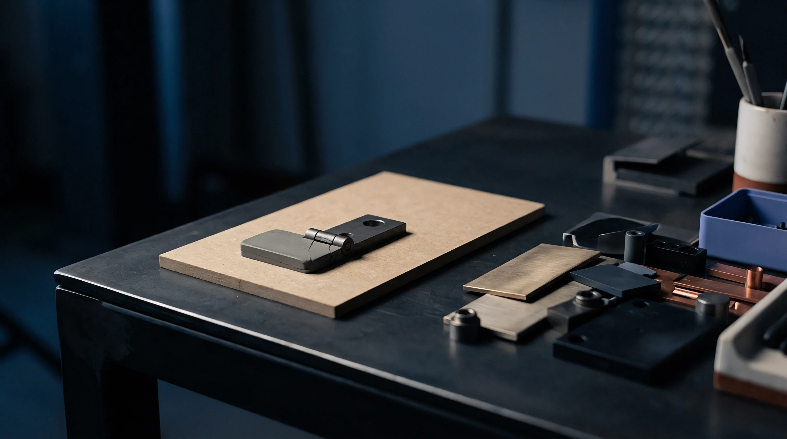
Purchase Order Specifications and Material Traceability Records
Clear wording in the master tooling agreement protects the buyer from unapproved material substitutions. The RFQ documentation defines steel origin, block dimensions, minimum surface hardness, and hardness testing procedures.
Surface degradation ruins part aesthetics. Specifying portable Leeb hardness verification tests across five discrete points per insert ensures heat treatment consistency across cavity faces.
- Material specification clauses mandate specific DIN or AISI grades, banning equivalent substitutions without explicit written consent from the lead tooling engineer.
- Bulk hardness verification clauses identify testing zones along functional parting lands, demanding certified Leeb or Equotip hardness readouts prior to shipping T1 trial shots.
- Weld repair documentation clauses stipulate that no structural cavity repairs occur without disclosing the filler wire chemistry, preheat cycle, and post-weld tempering steps.
- Recast remediation requirements define mechanical polishing steps across all EDM-burned surfaces, mandating complete optical removal of the white layer.
Under ISO 10204 type 3.1 inspection certification rules, the metal manufacturer must validate that the delivered stock complies with the contractual chemical analysis and mechanical hardness limits before the customer accepts commercial ownership.