Thermal Expansion Mechanics in High Precision Micro Injection Molds
Controlling tool thermal expansion within one degree Celsius secures sub-three-micron part tolerances in precision micro injection molding.
Equilibrium
Thermal Mass and Micro-Scale Sensitivity
Dimensional control in micro injection molding hits limits where traditional tooling allowances break down. When parts weigh under a milligram and feature details sit below fifty micrometers, cavity steel temperatures govern part geometry almost instantly. Cavity plates expand and contract along predictable thermal coefficients, but micro-scale features magnify that movement relative to part size.
A drift of just five-degree Celsius in cavity block temperature expands the steel enough to wipe out the entire tolerance band on an optical lens or a medical micro-fluidic channel.
Mold temperature control depends on balancing heat injected with each shot against the heat drawn off through cooling channels. In micro-molding, shot volume is negligible compared to the thermal mass of the mold base. Melt heat enters in brief, concentrated bursts, leaving boundary-layer heat transfer to drive tool behavior.
Far from staying static, steel temperature cycles between injection contact and cooling intervals, and holding dimensional stability across thousands of shots comes down to dampening those swings.
DIN 16742 Group 1 precision tolerances mandate that tool temperature fluctuations remain within one degree Celsius to prevent dimensional drift beyond three micrometers across cavity arrays.
Cooling line layout sets the baseline for tool stability. Micro-tools leave virtually no room for conventional water lines near part features, forcing designers to push oil or water circuits deep into the mold plates. That distance stretches thermal paths and dulls response to localized heat spikes.
Heat builds around slender cores and micro-ejector pins, triggering local growth that distorts part geometry regardless of what the main cavity plate is doing.
Transient State Instability across Production Shifts
Startup runs show pronounced dimensional drift as tooling comes up from room ambient to steady operating temperature. A tool certified under equilibrium conditions typically throws out-of-spec parts for its first fifty to one hundred cycles. Polymer entering cold cavities freezes early against steel dimensions that sit below nominal.
Only as the tool reaches equilibrium do core plates expand to working position, opening cavity volumes and extending flow lengths.
Intervening at the press during startup often ruins process capability over the shift. Adjusting pack pressure or barrel heats to bring early warm-up parts into tolerance guarantees parts will drift out of tolerance once the tool heat-soaks. Stable validation requires running mold temperature controllers for at least forty-five minutes before shooting resin, bringing the clamping block and plates into thermal equilibrium.
Ambient factory conditions create another source of drift across multi-shift runs. Day-to-night temperature swings alter heat loss from uninsulated mold sides through convection and radiation. Housing micro-molding clamp units inside temperature-controlled cleanroom enclosures shields the tool from ambient air currents and fixes boundary heat transfer rates.
Transient thermal boundary growth directly skews cavity-to-cavity balance across extended production shifts.

Expansion
Differential Material Growth Mechanics
Tool construction pairs dissimilar alloys to balance mechanical strength, thermal conductivity, and wear life. Each alloy expands at its own rate, measured in microstrain per Kelvin. When tool steel, copper alloys, and tungsten carbide sit in the same assembly, temperature changes generate shear and compressive stresses across mating faces.
Tool steel expands faster than tungsten carbide inserts, while beryllium-copper core pins out-expand the surrounding steel cavity plate.
Mating components under severe thermal gradients either bind or open unwanted clearances. Pairing a hardened steel pocket at eleven point seven microstrain per Kelvin with a beryllium-copper insert at seventeen point five microstrain per Kelvin yields nearly six micrometers of differential expansion per hundred millimeters over a fifty-degree temperature rise. The expanding beryllium-copper insert exerts heavy compressive stress against pocket walls, bowing parting lines and distorting fragile cavity geometry.
| Material Grade | Composition Category | Expansion Coefficient (10^-6/K) | Thermal Conductivity (W/m·K) | Yield Strength (MPa) |
|---|---|---|---|---|
| 1.2343 / H13 | Hot Work Tool Steel | 11.7 | 24.3 | 1650 |
| 1.2083 / 420SS | Martensitic Stainless Steel | 10.5 | 19.0 | 1500 |
| Ampcoloy 940 | Copper Nickel Silicon Alloy | 16.2 | 208.0 | 680 |
| Moldmax XL | Beryllium Copper Alloy | 17.5 | 130.0 | 800 |
| K30 / WC-Co | Tungsten Carbide Sub-micron | 4.5 | 80.0 | 2600 |
Sub-micron core pins fixed in steel plates pose severe alignment problems. Heat forces these pins to grow both radially and axially. Radial expansion eats up slide clearance until pins begin galling pocket walls during cycling.
Axial growth thrusts pin faces forward into the cavity, leaving witness marks on molded parts or risking mechanical damage on mold close.
Anisotropic Expansion in Asymmetric Cavity Inserts
Micro-cavities rarely absorb heat symmetrically. Thin-to-thick wall transitions, internal ribs, and off-center gates set up steep thermal gradients across insert bodies. The warmer side of an insert expands more than the cooler side, twisting flat faces and pulling straight features out of square.
That distortion opens gaps at parting lines, letting low-viscosity melts flash.
Tungsten carbide cavity inserts exhibiting a coefficient of thermal expansion of 4.5 microstrain per Kelvin restrict boundary displacement to less than half that of tool steel under identical cyclic thermal loads.
Controlling uneven thermal growth requires targeted cooling placed directly behind heat-concentration points. Conformal cooling channels built via laser powder bed fusion can follow complex cavity profiles, smoothing thermal gradients across the insert. Stripping out hot spots keeps expansion uniform and maintains parallel cavity shut-offs through long runs.
Unchecked differential expansion leads directly to tooling wear, cavity binding, and dimensional scrap across multi-cavity layouts.
- Parting Line Flash Formation occurs when core expansion forces mold plates apart locally, opening gaps exceeding five micrometers along cavity edges.
- Ejector Pin Scoring arises when differential growth between ejector plates and cavity blocks skews pin alignment, driving hardened steel surfaces into binding contact.
- Core Pin Deflection results from asymmetric heat buildup causing unilateral thermal growth that skews delicate micro-cores away from centerlines.
- Cavity Pocket Galling develops when high-expansion copper alloy inserts expand against restrictive steel pocket walls, exceeding material yield points and galling sliding contact faces.
Matching thermal expansion coefficients across tool components preserves mechanical alignment over wide working temperature windows.
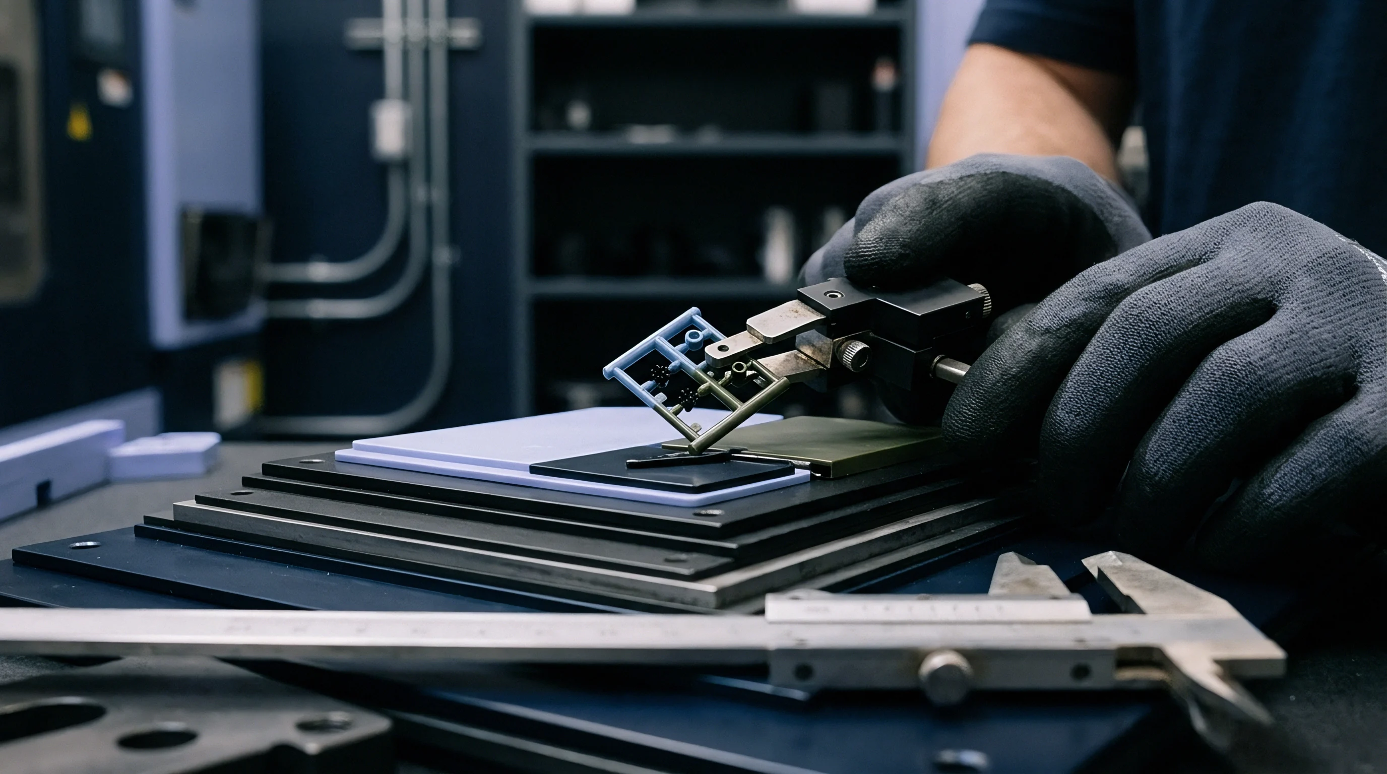
Zone
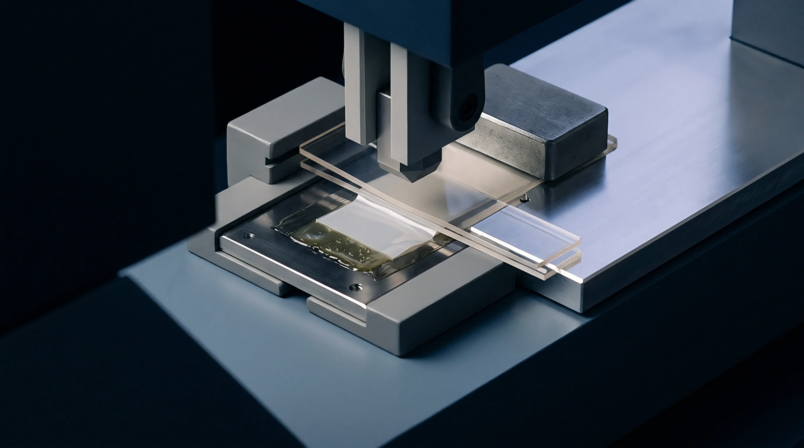
Micro-Gate Shear Heating and Localized Heat Flux
Forcing melt through micro-gates under high injection pressure generates severe viscous shear heating. In gates under two hundred micrometers, shear rates routinely exceed one hundred thousand reciprocal seconds. That mechanical shear converts directly into thermal energy, spiking local melt temperatures by twenty to forty degrees Celsius within the gate land.
The heat conducts immediately into the surrounding gate steel, creating an isolated, high-temperature expansion zone.
That local thermal expansion chokes the gate opening. As steel expands inward, it narrows the gate aperture during high-speed injection. The tighter constriction drives shear rates and melt temperatures higher still.
Left unaddressed, this cycle degrades shear-sensitive resins, produces gate blush or discoloration, and causes dimensional inconsistency in features adjacent to the gate.
| Gate Diameter (µm) | Volumetric Flow Rate (cm³/s) | Calculated Shear Rate (1/s) | Local Melt Temp Rise (°C) | Steel Zone Growth (µm) |
|---|---|---|---|---|
| 300 | 2.5 | 37,700 | 8.2 | 0.8 |
| 200 | 2.5 | 127,300 | 18.5 | 1.9 |
| 150 | 2.0 | 226,300 | 27.4 | 2.8 |
| 100 | 1.5 | 382,000 | 41.1 | 4.2 |
| 50 | 0.8 | 651,900 | 63.8 | 6.7 |
Pulling heat away from micro-gates requires high-conductivity inserts. Copper-beryllium or copper-nickel-silicon alloys seated around the gate drop draw heat away from the land area and route it into primary cooling lines. Dissipating that energy stabilizes gate dimensions and keeps fill rates uniform across cavities.

Hot Runner Thermal Leakage into Cavity Blocks
Direct hot runner drops eliminate runner waste in micro-molding, but they complicate heat management. Nozzles run at processing temperatures between two hundred to three hundred fifty degrees Celsius, positioned millimeters away from cavity steel held at forty to eighty degrees Celsius. Even with insulating air gaps and seals, heat bleeds across by conduction and radiation.
Nozzle heat leakage creates hot zones around cavity gate entries. The steel near the nozzle runs warmer than surrounding plate areas and expands accordingly. Higher local steel temperatures slow resin cooling in the gate region, setting up differential shrinkage across the part.
Parts warp toward these hotter gate areas as cooling rates diverge across the geometry.
Maintaining turbulent flow inside micro-channel cooling circuits prevents localized heat accumulation near narrow runner entrances.
Halting thermal leakage requires tip insulators machined from low-conductivity ceramics like zirconia. Zirconia supports heavy clamp loads while blocking heat transfer from nozzle to cavity plate. Tight machining on nozzle seats prevents plastic leakage while keeping metal contact to a minimum, preserving the thermal break between runner and cavity.
Unmanaged shear heating and hot-runner leakage cause localized thermal distortion that permanently compromises cavity geometry.
Gap
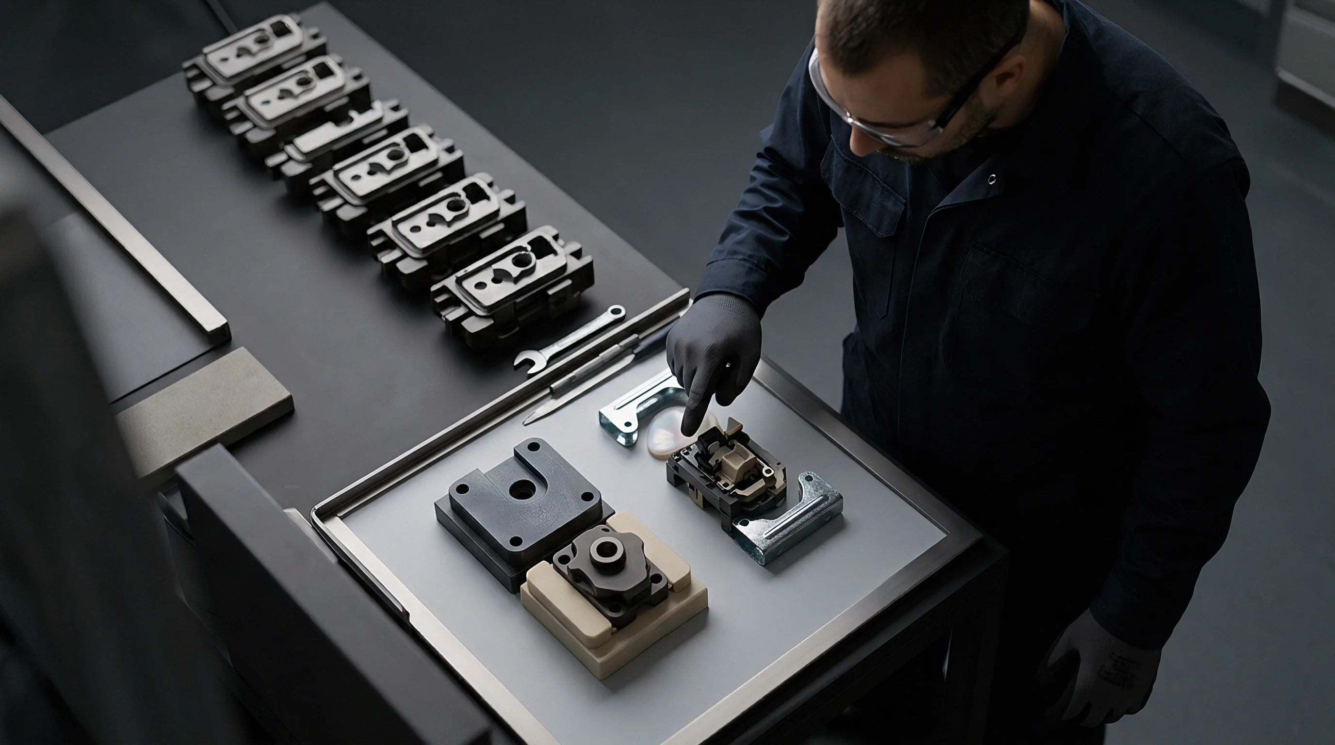
Interstitial Clearance Thresholds and Flash Mechanics
Micro injection molding relies on low-viscosity, high-flow resins formulated to pack out sub-millimeter features. Under injection pressure, these materials flash into microscopic gaps. Tooling clearances around sliding cores, ejectors, and parting lines must stay below tight mechanical thresholds.
Flash on micro-components interferes with downstream automated assembly, damages mating parts, and throws functional dimensions out of tolerance.
Thermal expansion alters these clearances during production. A tool fitted to tight tolerances on the bench changes as it heats. Differential growth either opens clearances or locks components together.
When adjacent steel blocks expand away from one another, sliding gaps widen and invite flash; when components expand toward each other, moving faces bind, gall, and halt production.
| Polymer Family | Viscosity Grade Class | Melt Temp Range (°C) | Flash Gap Threshold (µm) | Critical Tool Temp (°C) |
|---|---|---|---|---|
| LCP (Vectra) | Ultra Low Viscosity | 330 – 350 | 2.0 | 90 |
| PA66 (Zytel) | High Flow Unfilled | 280 – 300 | 3.5 | 80 |
| POM (Delrin) | Standard Micro Grade | 190 – 215 | 5.0 | 65 |
| PEEK (Victrex) | Low Viscosity Micro | 380 – 400 | 2.5 | 160 |
| PC (Lexan) | High Flow Optical | 290 – 310 | 6.0 | 85 |
Calculating working clearances demands mapping thermal growth through every assembled layer. Designers apply temperature-dependent expansion calculations to each detail drawing to ensure clearances remain inside flash limits at steady-state operating temperatures. Because these growth values match the scale of micro-features, tool inserts must be machined to sub-micrometer tolerances.
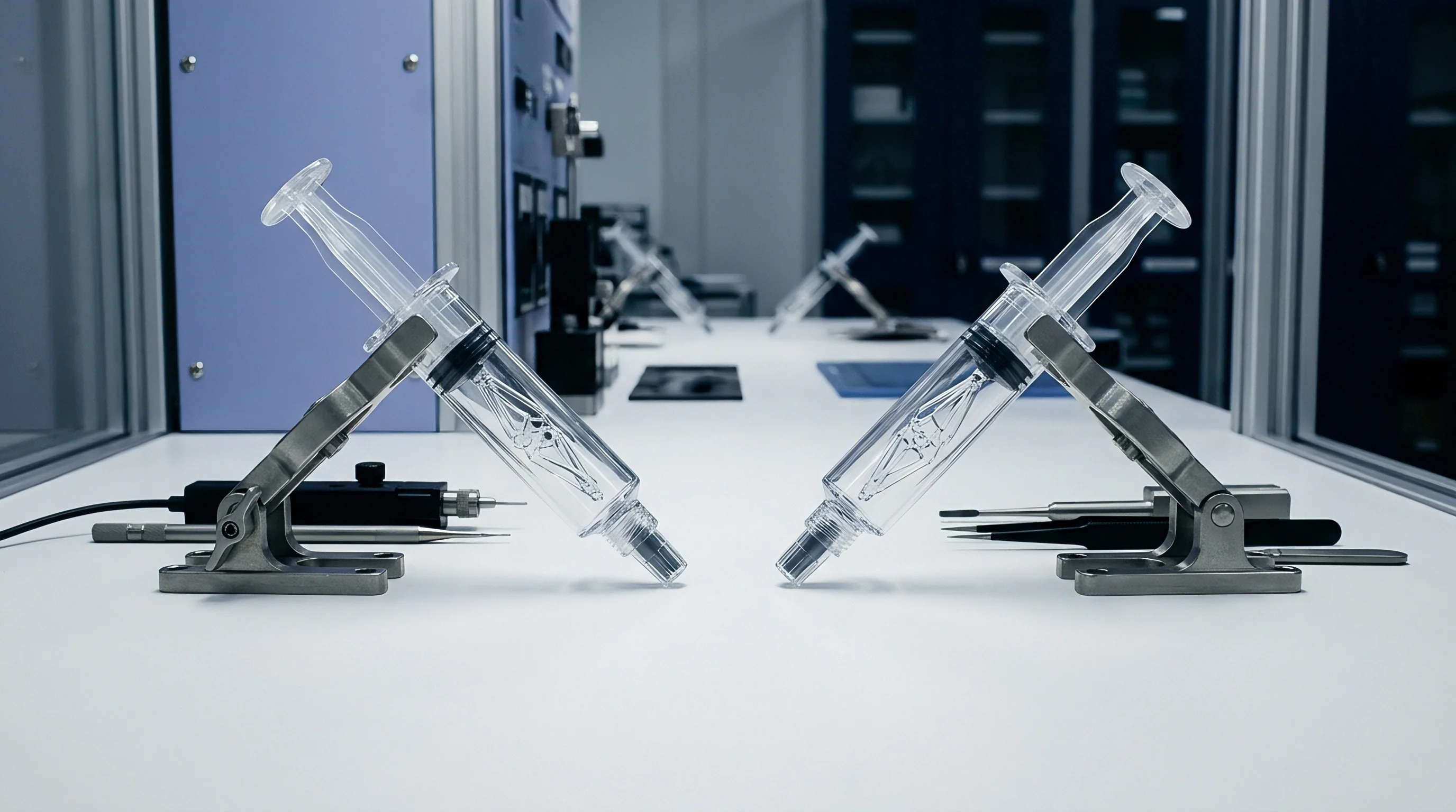
Thermal Adjustment Protocol for Sliding Micro-Cores
Establishing clearance stability across operating states requires a disciplined commissioning sequence.
- Measure ambient baseline dimensions for all sliding cores, guiding tracks, and pocket walls using optical coordinate measurement equipment at twenty degrees Celsius.
- Calculate theoretical thermal expansion vectors for each individual component using maximum hot runner radiation and process oil bath heating parameters.
- Grind initial fitting clearances into core guide surfaces, incorporating differential expansion offsets calculated between steel plates and copper alloy inserts.
- Mount cavity plates onto temperature-controlled hot plates, heating assemblies to target steady-state production operating temperatures.
- Perform high-contrast optical inspection of interstitial gaps at parting lines and sliding interfaces to verify gaps remain under two micrometers.
- Inject low-viscosity trial resin at working pressures and perform flash verification checks under fifty-times optical magnification.
- Adjust oil controller temperatures in one-degree increments to fine-tune final thermal expansion clearances before starting production approval runs.
Failure to maintain physical gap limits under elevated thermal conditions makes it difficult to determine whether resin flow exceeded specification or thermal expansion forced the parting line open.

Correction
CAD Scaling and Toolroom Compensation Strategies
Molded parts shrink as they cool from melt temperatures to ambient. Toolmakers typically account for this by scaling CAD cavity models larger than target part dimensions. Standard molding relies on uniform, isotropic shrink values taken straight from material datasheets.
For micro-molding, uniform scaling fails.
Volumetric shrinkage in micro-features is highly anisotropic, driven by high molecular orientation, rapid thermal quench, and geometric constraint. At the same time, mold steel expansion counteracts polymer shrinkage: the final part dimension is the net difference between tool thermal growth and polymer contraction. Designing micro-cavities requires calculating a combined offset for both variables at once.
Accurate cavity sizing relies on non-linear dimensional compensation. High-heat regions of a cavity expand more during molding, requiring smaller shrinkage allowances in those zones. Very thin ribs freeze almost instantaneously on contact with the mold and show almost no post-mold shrinkage compared to thicker bosses or walls.
Toolmakers therefore cut micro-cavities using localized, variable scaling factors across the geometry.
Electrode design for electrical discharge machining must incorporate these same thermal adjustments. EDM spark overcut, electrode expansion during fabrication, and tool steel operating growth must be calculated as an integrated chain. An error at any stage propagates straight into the molded product.
Verification and Qualification under ISO 20753 Standards
Validating micro-molds requires rigid dimensional inspection under tightly controlled conditions. ISO 20753 outlines standard test specimens and methods, but micro-scale parts demand non-contact metrology. Mechanical calipers and coordinate-measuring touch probes deflect micro-features and generate false readings.
Isothermal tool stabilization during initial production setup eliminates early-shot dimensional variance prior to part collection.
Non-contact systems ~ including white-light interferometry and confocal microscopy ~ deliver reliable profiles of micro-cavities and molded parts. Metrology must be conducted in labs maintained at twenty degrees Celsius per international standards. Parts ejected from micro-tools require twenty-four hours of conditioning in that controlled atmosphere to reach dimensional stability before inspection.
Tool qualification demands measuring cavities cold at ambient and hot at operational steady state. Comparing ambient and operating measurements validates thermal growth models against physical reality, proving the tool expands as engineered. Quality dossiers require both datasets to establish baseline dimensions for future wear analysis.
Procurement contracts require tools that fail hot thermal validation to undergo shop rework before final acceptance.
- Thermal Audit Baseline Verification validates cold cavity optical measurements against master CAD files using three-dimensional coordinate point clouds.
- Operational Heat Soak Testing tracks cavity plate growth across four hours of continuous heating using laser displacement sensors.
- Multi-Cavity Array Uniformity Checks confirm that thermal expansion remains equal across all cavity positions within a two-micrometer window.
- Post-Mold Shrinkage Stabilization Tracking records part dimensional changes over seventy-two hours to isolate structural thermal relaxation from tool growth errors.
Capturing accurate thermal growth baselines ensures dimensional repeatability during multi-site manufacturing transfers.


Cost

Amortization of High-Precision Thermal Hardware
Stabilizing mold temperature at micro tolerances demands considerable capital investment. Adding conformal cooling inserts, isolated hot runner systems, high-conductivity copper alloys, and multi-zone oil controllers can easily double or triple mold build costs. A conventional single-cavity micro-mold in hardened steel might run twenty-five thousand dollars, while an insulated, conformally cooled tool with embedded sensors can top seventy-five thousand dollars.
Evaluating that spend requires looking at cost per good part over the life of the program. Controlled thermal tooling eliminates warm-up scrap, trims cycle time with faster cooling, and prevents thermal fatigue cracking in fragile details. In high-volume medical micro-molding, eliminating a two percent scrap rate across a ten-million-part run pays back the tooling premium within months of commissioning.
Tool maintenance budgets must also factor in thermal fatigue. Repeated expansion and contraction cycles concentrate stresses at sharp corners and insert boundaries. High-conductivity copper alloys lack the yield strength of hardened tool steels, meaning insert replacement is a regular operating expense across multi-million-shot production runs.

Scrap Financial Impact Driven by Process Instability
Running micro-tools without precise thermal regulation produces hidden costs that eat into margins. Scrapped parts during thermal transitions burn expensive engineering resins, press hours, and cleanroom operator time. Specialty polymers like PEEK or LCP cost over one hundred dollars per kilogram, meaning two hours of unstable startup cycling on a multi-cavity tool bins hundreds of dollars in resin alone.
Unnoticed dimensional drift mid-run carries far larger commercial consequences. Out-of-tolerance micro-parts delivered to customer automated assembly lines trigger line stoppages, warranty exposure, and complete lot rejections. In-line vision systems positioned at the press catch thermal drift immediately, stopping cycles the moment critical dimensions begin migrating out of tolerance.
Supply agreements increasingly feature tool capability clauses that assign the cost of thermal instability to the toolmaker. If a mold cannot maintain required cavity dimensions at production temperatures, the builder carries the cost of re-machining, modifications, and re-qualification until the process proves capable.
Addressing thermal management early in tool design fixes piece costs, protects operating margins, and ensures reliable production over the long haul.