Calculating Thermal Expansion Offsets in Hot Runner Manifolds
Hot runner manifold expansion calculations require reducing cold nozzle pitch dimensions relative to a fixed locating center based on steel thermal growth.
Steel
A toolroom measurement of 150.00 mm between nozzle drops on an ambient manifold becomes an engineered misalignment once the manifold reaches 280°C while the surrounding mold plate remains at 30°C. Steel expands predictably under thermal load. When a toolmaker cuts nozzle pocket centers into a cavity plate, those pockets sit at positions governed by mold base temperature. The manifold block, insulated inside pocket clearances and heated by internal cartridges or cast-in elements, expands outward from its central locating point.
Offsetting the cold nozzle tips in their pockets allows thermal growth to draw the nozzle centerlines into alignment with the cavity gates at operating temperature.
The scale of this shift depends on alloy selection, the thermal delta between the manifold and surrounding tool plates, and distance from the locating dowel. Tool steels common in hot runner construction have mean linear thermal expansion coefficients between 11.5 × 10⁻⁶ /°C and 13.2 × 10⁻⁶ /°C within normal processing ranges. Titanium backup pads and ceramic insulators curb conductive loss into the mold frame, but the temperature delta across the manifold body itself still drives overall dimensional growth.
Calculating the expansion vector starts from the manifold’s fixed reference point—typically a hardened center ring or central dowel pin that sees zero lateral shift against the tool frame. Every drop nozzle travels radially outward from this datum. A two-drop linear manifold expands along a single axis, but a sixteen-drop matrix expands along two orthogonal axes at once, compounding pitch errors at outlying drops whenever cold offsets are neglected.
| Material Designation | Standard Alloy Equivalent | Temperature Range (°C) | Mean Expansion Coefficient (10-6 /°C) |
|---|---|---|---|
| 1.2344 / H13 | X40CrMoV5-1 | 20 to 300 | 12.4 |
| 1.2312 / P20+S | 40CrMnMoS8-6 | 20 to 200 | 12.8 |
| 1.2738 / P20+Ni | 45NiCrMo16 | 20 to 200 | 13.0 |
| 1.2316 / Stainless | X38CrMo16 | 20 to 300 | 11.8 |
| 3.7165 / Ti6Al4V | Grade 5 Titanium | 20 to 300 | 9.2 |
| 1.3343 / M2 | HS6-5-2 High Speed Steel | 20 to 300 | 11.9 |
Ignoring thermal growth during tool design forces severe mechanical stress into the hot runner assembly and cavity plates, with failure following distinct paths depending on system rigidity and nozzle sealing:
- Nozzle Stem Shearing occurs when rigid valve sleeves or nozzle bodies crowd against cold pocket walls until tips bend past their yield point.
- Melt Seal Decoupling happens on sliding pressure seal interfaces when thermal movement alters seal pre-load, spilling polymer into the manifold pocket.
- Gate Wall Scoring develops as un-centered nozzle tips scrape against hard cavity inserts during warmup, gouging polished gate lands.
- Dowel Pin Deformations result from constrained expansion where manifold locating pins absorb uncompensated lateral thrust, galling alignment bores in the backing plate.
A hot runner manifold operating at 280°C inside a 30°C mold plate expands 0.310 mm across a 100 mm pitch distance when constructed from standard H13 tool steel.
Failing to program cold offsets into CNC routines leaves a tool that binds during thermal preheating. When steel yields under that expansion pressure, plasticized resin floods the void between the galled manifold body and the pocket housing, destroying heater elements and forcing a costly teardown.
Pitch
Centerline spacing between cavity gates dictates runner layout, but an engineering pitch callout of 180.00 mm belongs strictly to the cold cavity inserts and the finished plastic part. Machining the manifold drops to that exact spacing guarantees axial runout once the block reaches processing temperature. The pitch cut into cold manifold steel must therefore be tighter than the cavity gate pitch.
Determining the necessary offset relies on standard linear thermal expansion to establish growth across a known distance:
ΔL = L0 · α · (Tmanifold – Tmold)
Here, ΔL represents the linear expansion offset in millimeters. L0 is the cold distance from the locating datum to the nozzle centerline. The variable α is the coefficient of thermal expansion for the alloy.
Tmanifold is the stabilized hot runner operating temperature, and Tmold is the regulated temperature of the cavity plates surrounding the pocket.
Grid layouts introduce two-dimensional expansion vectors. A nozzle sitting at X = 120.00 mm and Y = 80.00 mm from the central dowel moves along a diagonal determined by its Pythagorean distance from center, rather than tracking parallel to the tool edges.
Calculate the cold coordinate position for any two-dimensional drop location using orthogonal displacement components:
Xcold = Xhot / (1 + α · ΔT)
Ycold = Yhot / (1 + α · ΔT)
Subtracting Xcold from Xhot yields the machining offset required for the X-axis CNC milling operations. The radial displacement vector equals the hypotenuse of the X and Y expansion components. Matching cold tool geometry to hot thermal equilibrium prevents off-center gate entry, valve pin binding, and uneven melt shear during injection high-pressure phases.
Cold manifold nozzle drops must sit closer to the central locating dowel than the corresponding cavity gates.
Plate
Housing plates carry the clamping and injection loads while maintaining runner alignment. Air gaps, insulation boards, and expansion dowel channels separate the hot block from the mold structure. Sizing the manifold pocket accurately means accounting for both outward expansion of the runner block and the modest thermal growth of the housing plates as they soak up heat during production.
Why Do Hot Runner Dowels Shear during Warmup?
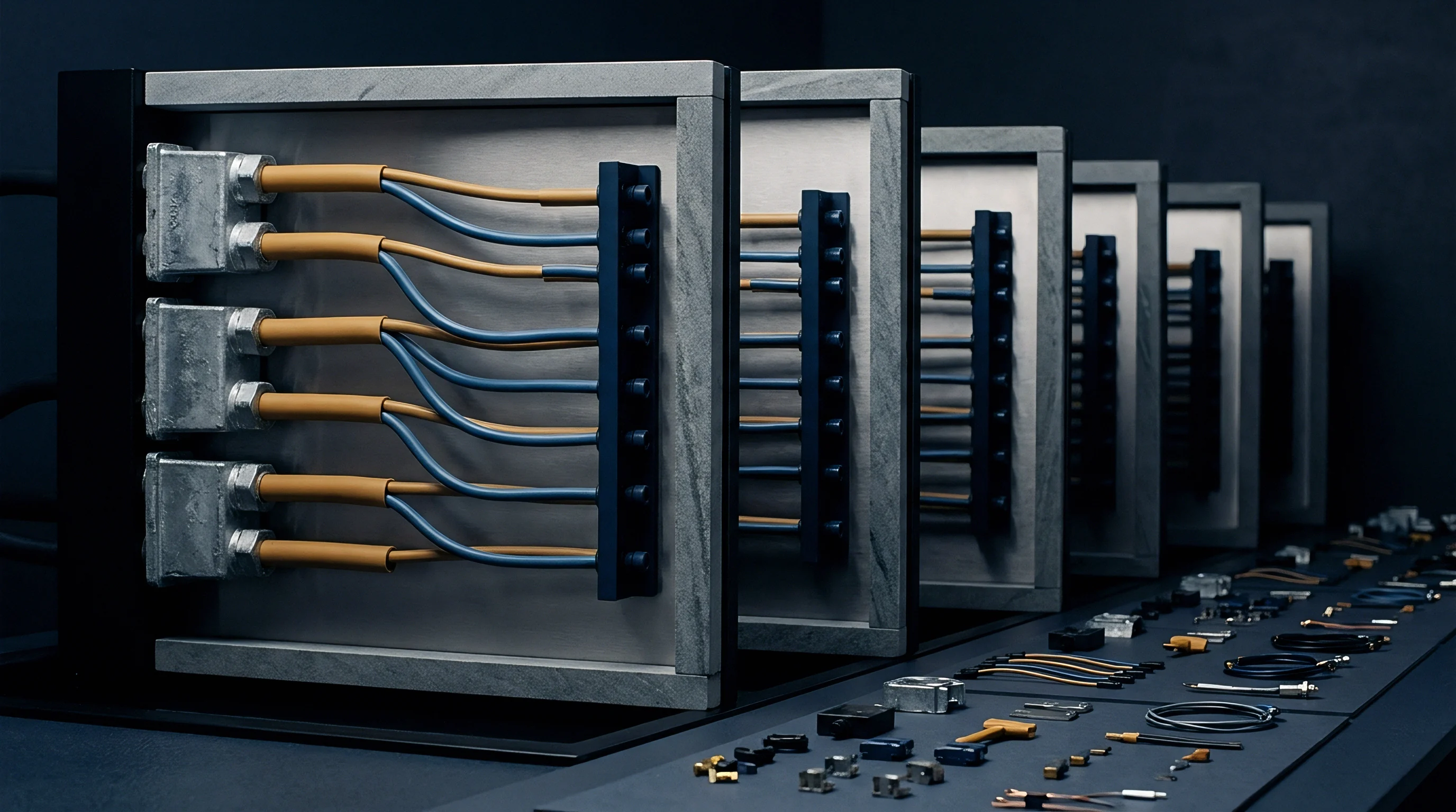
Locating pins shear when thermal expansion runs into rigid constraints without expansion clearance. Placing standard cylindrical dowels at the outer corners of a manifold anchors the steel where it needs to move, building up severe shear loads. Hardened pins bend or gouge into soft backing plates as the block pushes outward.
Sound design relies on a single central dowel pin for the absolute X-Y zero datum, paired with precision sliding keys or slotted dowel channels along the principal axes. These slots allow guided radial travel while maintaining angular alignment of the manifold assembly.
Pocket clearances in the main plate must handle maximum thermal growth plus wire routing space. An uncompensated pocket wall limits the expansion path, turning the manifold into a hydraulic ram that deforms outer plate walls and shifts cavity alignment.
Select locating hardware and pocket clearances according to specific structural function:
- Central Locating Rings fix the central sprue axis in place, anchoring the manifold against rotational and lateral translation.
- Axial Guide Keys permit linear slide along the centerlines while preventing angular twisting of long manifold bars.
- Slotted Dowel Bushes absorb differential expansion along the long axis without losing perpendicular guidance on high-drop count tools.
- Titanium Support Buttons minimize heat transfer to cavity plates while sustaining clamping force loads across the sealing plane.
Machining housing pockets without thermal expansion allowances violates tool construction standard DIN 16742, voiding core concentricity tolerances on precision molded parts.
Toolrooms frequently diagnose valve stem drag during initial heat-up as contamination in the guide bushings. In most cases, the real culprit is an undersized manifold clearance pocket that forces the expanding block against guide pins, tilting the valve pin guide sleeves out of perpendicularity.

Arithmetic
A four-drop inline manifold producing medical polycarbonate components illustrates how these offsets translate to CNC machining coordinates. The part print specifies four gates spaced on a straight line at 120.00 mm intervals, giving a 360.00 mm span from drop one to drop four. The locating dowel sits midway between drops two and three, establishing the origin datum at the geometric center.
System operational parameters establish the precise thermal delta:
- Define the manifold alloy as H13 tool steel with a CTE of 12.4 × 10⁻⁶ /°C.
- Set the target hot runner operating temperature to 290°C for processing polycarbonate.
- Establish the regulated mold base plate temperature at 80°C.
- Calculate the thermal differential: ΔT = 290°C – 80°C = 210°C.
- Determine hot distances from central datum: Drop 2 = 60.00 mm; Drop 1 = 180.00 mm.
- Calculate cold position for Drop 2: Lcold = 60.00 / (1 + (12.4 × 10-6 × 210)) = 59.844 mm.
- Calculate cold position for Drop 1: Lcold = 180.00 / (1 + (12.4 × 10-6 × 210)) = 179.533 mm.
- Subtract cold position from hot position to find required machining offset: Drop 2 offset = 0.156 mm inward; Drop 1 offset = 0.467 mm inward.
Drop 1 requires an inward shift of almost half a millimeter. Cutting the cold manifold at nominal 120.00 mm pitch leaves Drop 1 roughly 0.467 mm off-center relative to its gate once hot, binding valve pins and blowing past nozzle seals under pressure.
| Datum Pitch Distance (mm) | Offset at ΔT = 150°C (mm) | Offset at ΔT = 200°C (mm) | Offset at ΔT = 250°C (mm) |
|---|---|---|---|
| 50.00 | 0.093 | 0.124 | 0.155 |
| 100.00 | 0.186 | 0.248 | 0.310 |
| 150.00 | 0.279 | 0.372 | 0.465 |
| 200.00 | 0.372 | 0.496 | 0.620 |
| 300.00 | 0.558 | 0.744 | 0.930 |
| 400.00 | 0.744 | 0.992 | 1.240 |
Two-dimensional layout profiles expand on radial vectors that require individual coordinate decomposition. For a matrix tool with drops positioned at X = 150.00 mm and Y = 100.00 mm under the same 210°C thermal delta, the cold X coordinate becomes 149.611 mm (0.389 mm offset) and the cold Y coordinate becomes 99.740 mm (0.260 mm offset). The total diagonal radial shift equals 0.468 mm along the expansion vector.
Precision nozzle alignment requires calculating thermal expansion from the fixed locating center rather than chaining dimensions from adjacent nozzle drops.
Commercial tooling contracts specify that manifold components must achieve dimensional alignment within a tolerance band of ±0.015 mm at setpoint temperature. A deviation outside this range transfers mechanical shear to nozzle tips, invalidating supplier warranty coverage for leak integrity.
Verification
Validating thermal calculations requires physical checks on the bench and in the press before injecting molten resin. Initial inspection uses dial indicators or an optical coordinate measuring machine at ambient room conditions to verify that cold drop spacing matches the offset dimensions on the tooling prints.
Dry heat trials check expansion under temperature without melt pressure. Thermocouples across all zone controllers confirm even heating; a manifold block with non-uniform heat distribution expands unevenly, bowing long bar faces. The assembly needs at least 45 minutes at operating setpoint to reach full thermal saturation throughout the core steel before measuring nozzle alignment.
Feeler gauges inserted through tool ports confirm that expansion clearances close to design specifications. High-temperature layout dye on nozzle seating rings verifies concentric engagement with cavity gates. Once the mold reaches heat, stroking the valve pin hydraulic or pneumatic actuation plates confirms free travel across every drop.
Any hesitation or binding signals axial misalignment caused by incorrect thermal expansion calculations.
Laser tracker measurements taken through open mold frames confirm that H13 hot runner blocks reach 98 percent of calculated expansion within 30 minutes of thermal stabilization.
Post-trial inspections verify that contact pressure seal surfaces show uniform compression footprints around the melt bore perimeter. Uneven witness marks indicate asymmetric expansion, requiring micro-shimming of support pads or adjustment of CNC machining offset tables. Catching these discrepancies early prevents blown seals, damaged drops, and recurring downtime across millions of injection cycles.