Selecting Injection Mould Cavity Alloys Based on Resin Filler Abrasiveness
Selecting cavity alloys for abrasive resins requires matching filler Mohs hardness and loading against steel carbide structure and toughness.

Grit
During the injection stroke, abrasive fillers strip steel from cavity walls through mechanical micro-ploughing and impact erosion. The rate and severity of that surface loss depend directly on particle morphology. Glass fibers, glass beads, mineral talc, calcium carbonate, and ceramic powders each behave differently when forced through restricted tooling channels under elevated pressure.
Polymer Matrix Filler Dynamics
Inorganic additives suspended in the resin follow velocity vectors governed by runner layouts and gate dimensions. Near obstructions, fibers quickly tumble out of parallel alignment and strike cavity walls at steep angles. Short glass fibers with high aspect ratios act as microscopic chisels whenever melt turbulence flips their orientation against the metallic substrate.
Round glass beads, by contrast, distribute compressive loads across blunt contact points, reducing localized shearing compared to sharp-edged milled fibers. Wear severity also compounds exponentially with filler concentration: increasing short glass fiber loading from fifteen percent to forty percent by weight elevates wear depth by a factor of six under identical injection speeds. In high-viscosity resins like polyetheretherketone or polysulfone, elevated shear stress pins hard particles against tool walls, accelerating surface loss.
Hard glass fibers aligned parallel to cavity surfaces create polished burnish paths, while high shear rates at restrictive gates flip fiber ends perpendicular to the melt stream and gouge tool steel.

Abrasive Hardness Ratings and Aspect Ratios
Crystalline structure governs how mineral and synthetic reinforcements interact mechanically with metallic tool surfaces. Mohs hardness ratings offer a reliable baseline for evaluating scratch potential against standard tool steel. Calcium carbonate sits low on the hardness scale and presents minimal wear risk under standard melt temperatures.
Solid glass reinforcement exceeds the hardness of pre-hardened mould steels, leaving unhardened cavity inserts vulnerable to rapid dimensional degradation. Synthetic ceramic reinforcements like silicon carbide or boron nitride present extreme hardness levels that scratch even hardened tool steels upon brief exposure.
| Filler Material | Mohs Hardness | Particle Geometry | Typical Loading Range (wt%) | Primary Wear Mechanism |
|---|---|---|---|---|
| Calcium Carbonate | 3.0 | Irregular Blocky | 10 – 40 | Mild Hydrodynamic Abrasion |
| Talc Mineral | 1.0 | Platy / Lamellar | 5 – 35 | Low Friction Sliding |
| E-Glass Fibers | 6.5 | Cylindrical Aspect Ratio 20:1 | 15 – 50 | Micro-Ploughing and Gouging |
| Wollastonite | 4.5 – 5.0 | Acicular Needles | 10 – 40 | Linear Scratch Abrasion |
| Silicon Carbide | 9.0 – 9.5 | Angular Crystalline | 5 – 20 | Severe Impact Erosion |
Particle geometry largely dictates whether sliding contact polishes or cuts into the mold steel. Cylindrical glass fibers maintain low drag along straight runner channels, yet create destructive impact patterns when striking core pins or wall radii. Acicular mineral structures like wollastonite exhibit moderate wear characteristics between talc and glass.
Matching cavity steel hardness to filler particle hardness remains an essential step in preventing premature cavity failure. Adding mineral talc to a glass-filled compound dampens fiber alignment perpendicular to the steel wall, reducing wear depth near high-velocity gate entries.
Substrate
Cavity steel selection establishes baseline resistance against physical wear, mechanical shock, and clamping tonnage across production runs. Mold designers weigh compressive strength, thermal conductivity, and microstructural carbide density when specifying cavity alloys. Standard pre-hardened steels suit non-abrasive resins, whereas heavily reinforced polymers require tool steels with dense vanadium or chromium carbide networks.
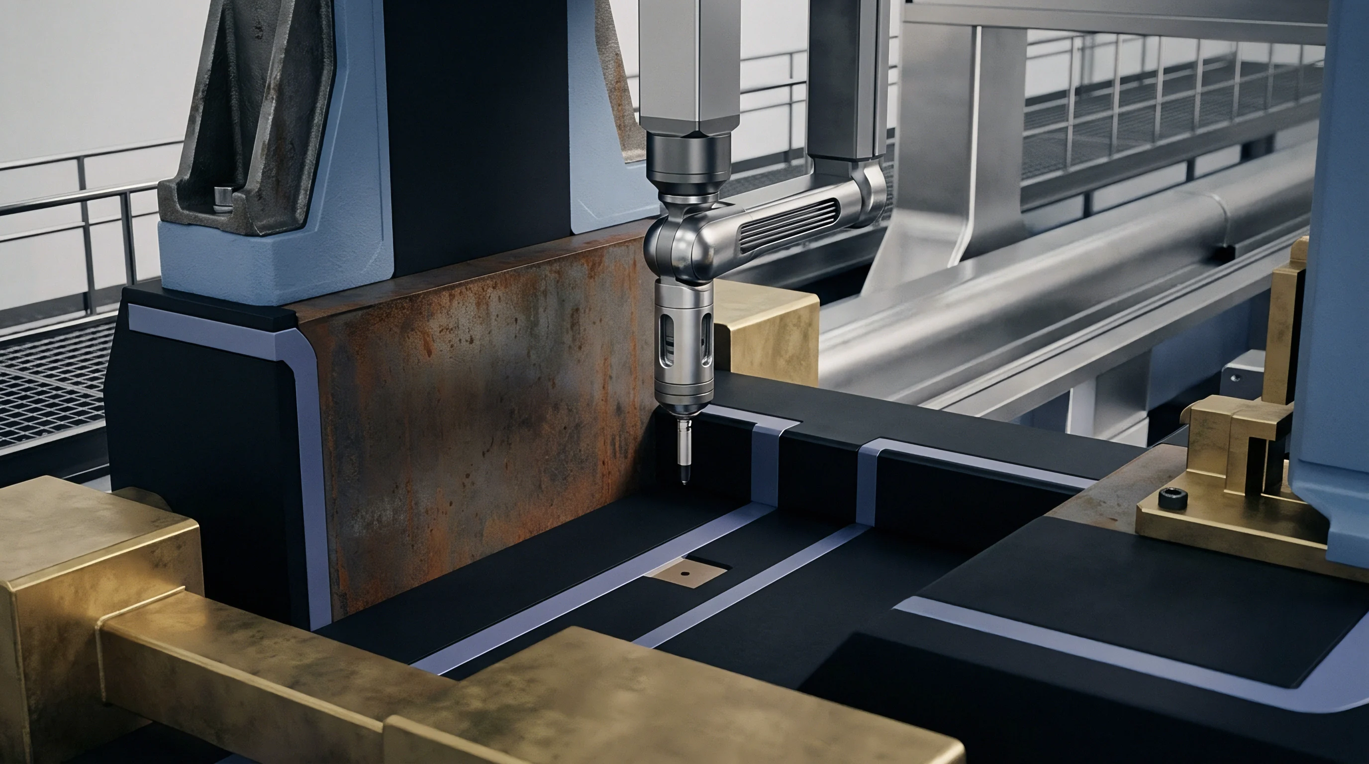
Tooling Steel Metallurgy and Hardness Horizons
Conventional pre-hardened grades perform adequately with unreinforced resins but degrade rapidly when exposed to glass reinforcement. AISI P20 offers excellent machinability and uniform structure at thirty Rockwell C, yet lacks sufficient carbide volume to prevent fiber gouging. Upgrading to AISI H13 through-hardened tool steel provides fifty-two Rockwell C hardness, doubling surface wear resistance under moderate glass loadings.
High-chromium stainless steels like AISI 420 combine forty-eight to fifty-two Rockwell C hardness with protection against corrosive degradation when processing flame-retardant glass-filled compounds.
Powder metallurgy cold-work steels carrying ten percent vanadium carbide maintain dimensional stability beyond one million shots in thirty percent glass-reinforced polyamides.
Powder metallurgy processing produces alloys with fine, uniform distributions of hard primary carbides that cannot be produced through conventional ingot casting. Alloys like CPM 10V or Vanadis 4 Extra incorporate elevated levels of vanadium carbide measuring nearly two thousand Vickers hardness. These hard carbide islands sit embedded within a hardened steel matrix, effectively blocking abrasive particles from ploughing through the material.
High-hardness tool steels prevent local gouging while preserving sharp corner radii across extended production cycles.

Copper Alloy Inserts and Carbide Dispersions
High thermal conductivity metals accelerate cooling cycles while specialized powder metallurgy formulations embed hard microscopic particles directly within the ferrous matrix. Copper-beryllium alloys like Moldmax HH achieve forty Rockwell C hardness while providing thermal conductivity four times greater than standard tool steel. These alloys suit gate inserts where heat extraction takes priority, though un-coated copper alloys experience elevated erosion rates when processing resins with glass fiber fractions above twenty percent.
High-strength copper-nickel-silicon alloys like Ampcoloy 940 offer safer handling during machining while matching thermal performance in high-wear core regions.
- Micro-chipping at Shut-offs occurs when high-hardness powder metallurgy steels lack sufficient Charpy impact toughness under heavy clamping force.
- Thermal Fatigue Cracking develops around water channels when high-hardness cavity inserts undergo aggressive cycling without adequate thermal conductivity.
- Gouge Formation at Gates emerges as high-velocity particulate streams strip unhardened martensitic matrix material from around iron carbides.
- Parting Line Roll-over happens when softer pre-hardened steels yield under continuous compressive loading alongside abrasive particulate entrapment.
| Alloy Grade | Standard Designation | Hardness Range (HRC) | Thermal Conductivity (W/m·K) | Charpy Impact V-Notch (J) | Glass Fiber Loading Threshold |
|---|---|---|---|---|---|
| AISI P20 | 1.2738 | 28 – 32 | 29 | 20 | Below 10 wt% |
| AISI H13 | 1.2344 | 48 – 54 | 24 | 18 | Up to 30 wt% |
| AISI 420 Stainless | 1.2083 | 48 – 52 | 20 | 14 | Up to 30 wt% (Corrosive) |
| CPM 10V | PM A11 | 58 – 62 | 21 | 10 | Exceeds 50 wt% |
| Ampcoloy 940 | C18000 | 28 – 32 | 208 | 25 | Requires Hard Coating |
Selecting a standard pre-hardened steel for forty percent glass-filled polyetheretherketone causes premature gate expansion, dimensional drift across critical wall sections, and unbudgeted tool replacement before the production order completes.


Coating
Surface engineering technologies deposit thin protective layers over cavity steel to reduce wear rates without altering core mechanical properties. Hard physical coatings act as sacrificial shields against particle scratching while low-friction formulations reduce drag along runner walls. Deposition methods must align with substrate heat treatment parameters to avoid annealing underlying tool steel.

Physical Vapor Deposition and Chemical Diffusion
Vacuum processing methods introduce hard nitrides or carbides directly onto tool steel surfaces at controlled vacuum pressure. Physical Vapor Deposition applies uniform layers of Titanium Nitride or Chromium Nitride at low processing temperatures, preserving substrate dimensions without phase transformation. Chromium Nitride provides a smooth surface finish with a low coefficient of friction, reducing resin drag and preventing glass fibers from gouging metal surfaces.
Titanium Aluminum Nitride yields superior oxidation resistance and hardness exceeding three thousand Vickers, protecting gates exposed to high-temperature abrasive polymers.
Compliance with DIN EN ISO 14923 for thermal sprayed and vapor-deposited coatings requires substrate stress-relief tempering before deposition to prevent core hardness loss.
Chemical diffusion processes modify the steel surface layer directly through atomic migration rather than physical adhesion. Plasma nitriding diffuses nitrogen atoms into the ferrous lattice at temperatures between four hundred eighty and five hundred thirty degrees Celsius. This creates a hard compound layer backed by a supporting diffusion zone that resists delamination under high mechanical pressures.
Diamond-Like Carbon deposits amorphous carbon matrices that combine extreme hardness with exceptional surface slipperiness, reducing ejector pin friction alongside filler abrasion protection.

Deposition Temperature and Core Tempered States
Applying surface treatments requires thermal balancing so the underlying substrate retains its heat-treated grain structure and yield strength. PVD coatings applied below five hundred degrees Celsius avoid tempering back hardened tool steels like H13 or CPM 10V. CVD techniques operating near nine hundred degrees Celsius require subsequent re-hardening and tempering steps in a vacuum furnace, introducing dimensional distortion risks on complex cavity details.
Inter-laminar flaking on sharp radii can stem from either non-uniform plasma density during deposition or extreme part geometry.
Erosion
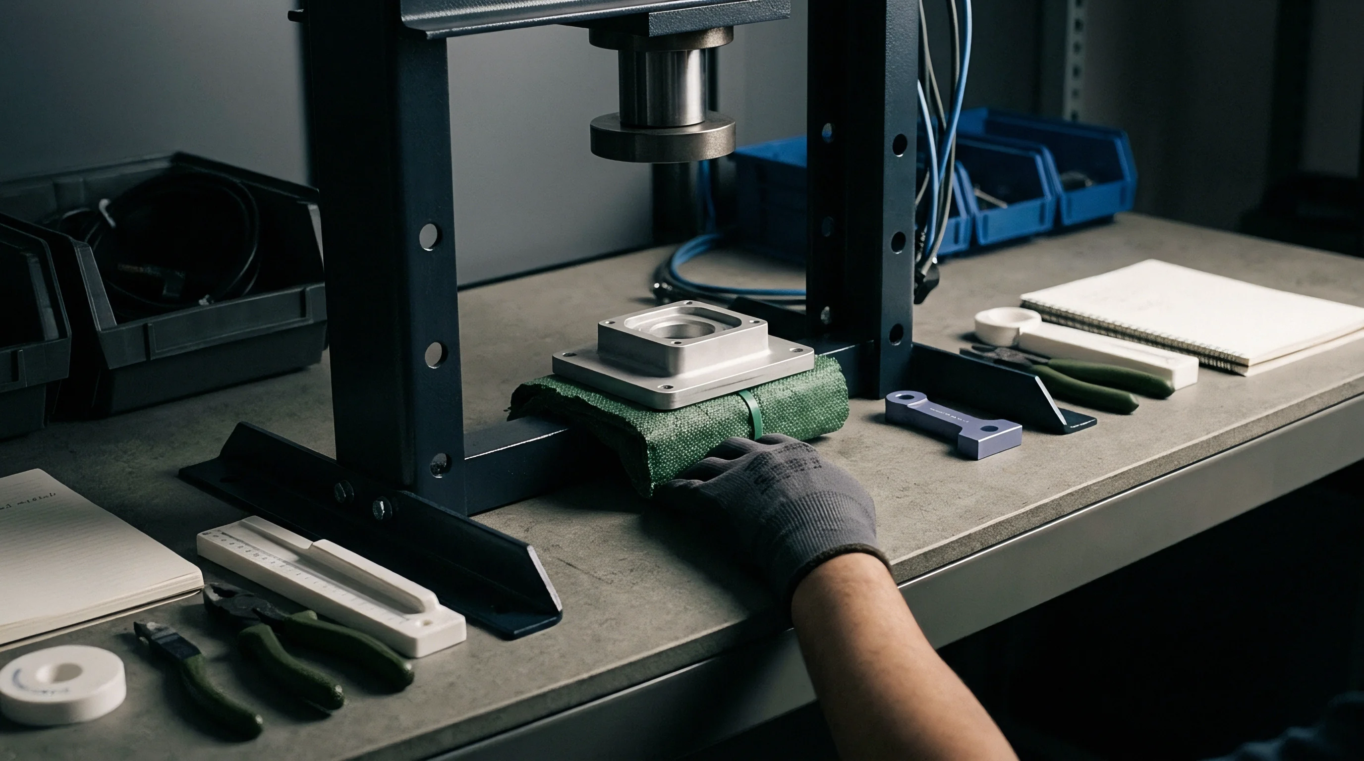
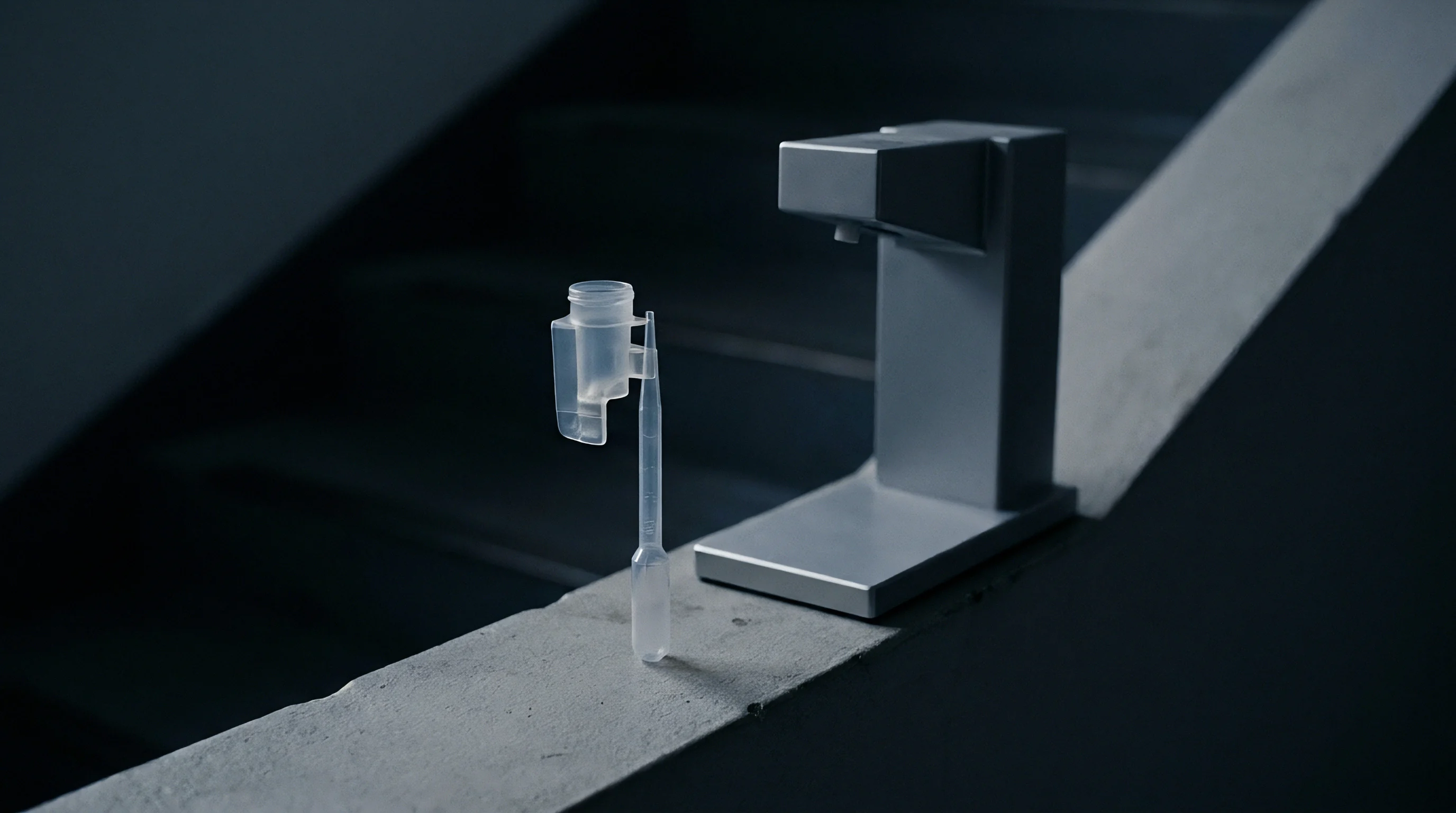
High-velocity resin flow strips metallic particles from mold surfaces, altering critical tolerances and gate geometries over time. Wear concentrations develop predictably wherever melt paths narrow, pivot, or encounter mechanical core features. Identifying wear zones allows engineers to implement localized insert strategies rather than manufacturing complete cavity blocks from expensive alloys.
Gate Washout and Divergent Shear Flow
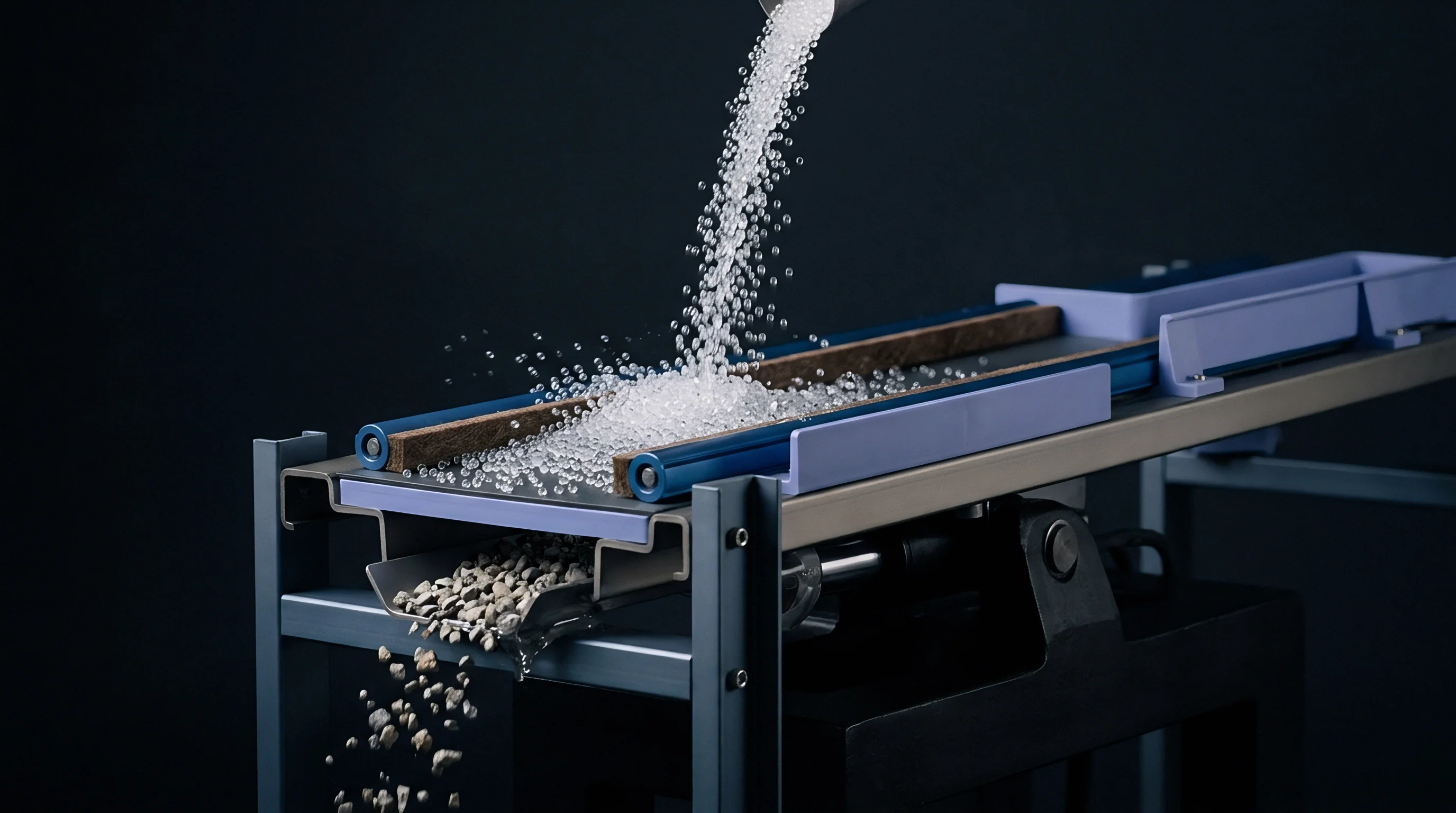
Restricted entry channels subject local steel to extreme melt velocities, producing localized pocketing where fluid orientation transitions abruptly. Submarine gates and pin-point gates endure intense shear forces as pressurized melt forces suspended fillers through orifice diameters under one millimeter. As steel erodes, the gate cross-section expands, causing pressure drops during cavity filling and generating unsightly vestige posts on ejected components.
Divergent flow areas behind core pins suffer double-sided impingement wear where split melt streams recombine under pressure.
- Calculate Melt Shear Rate at the restrictive gate region using maximum injection speed and gate cross-sectional dimensions.
- Evaluate Filler Concentration and mechanical hardness on the Mohs scale against substrate yield limits.
- Specify Insert Metallurgy that matches the expected abrasive loading and mechanical impact stress.
- Define Surface Treatment Parameters to preserve substrate core hardness while establishing hard surface protection.
Corrosion Wear Interdependence in Fluoropolymers
Aggressive outgassing during high-temperature melt processing weakens metallic crystal boundaries, accelerating mechanical removal by hard fillers. Fluoropolymers and halogenated flame retardants release acidic compounds like hydrofluoric or hydrochloric acid during plasticization. These acids attack iron matrices surrounding hard carbide phases, stripping support from tungsten or chromium carbides.
The combined action of chemical corrosion and mechanical abrasion destroys unprotected tool steel at three times the rate of mechanical wear alone. Hard stainless steels or high-nickel protective coatings prevent acid attack from loosening primary carbide particles.
Abrasive resin wear accelerates rapidly wherever runner systems force liquid polymer to make sharp right-angle directional changes.
Parting line edges experience edge-collapse under high clamp tonnages combined with abrasive flash infiltration. Including a wear-limit clause referencing ISO 2808 surface profile testing in the tooling contract establishes objective criteria for declaring cavity insert failure.
Trial
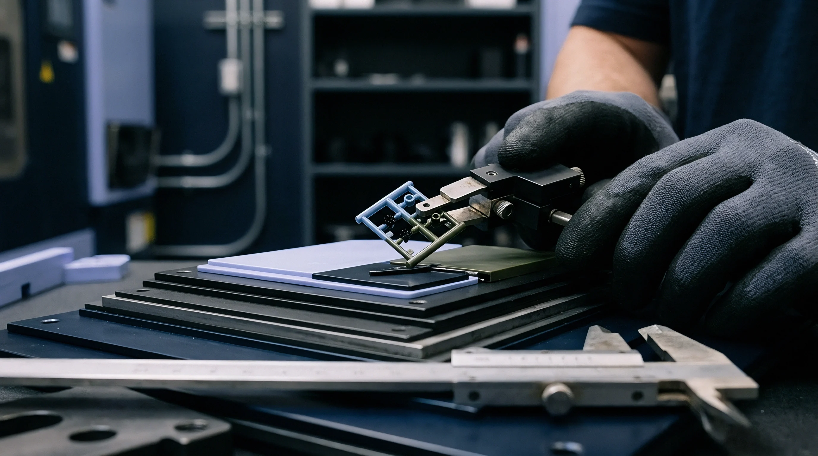
Measuring cavity degradation during initial production runs validates alloy selection before full-scale manufacturing commitments. Toolroom technicians apply non-contact profiling and mass balance checks during mold maintenance tear-downs. Systematic inspection identifies unexpected erosion patterns, allowing toolmakers to optimize gate entry shapes or upgrade insert alloys prior to high-volume production schedules.
How Do Toolrooms Quantify Gate Erosion Field Rates?
Dimensional inspection of first-article mouldings combined with laser scanning reveals microscopic material removal around entry channels. Toolmakers record baseline dimensions on pristine steel inserts using three-dimensional coordinate measuring machines before initial plastic sampling. Comparing moulded component gate vestige against historical baseline dimensions establishes real-world steel wear per ten thousand injection cycles.
Sudden increases in component weight indicate widespread cavity wall thinning caused by abrasive scouring.
- Cavity Mass Verification tracks tool steel removal through high-precision analytical balance weighing during routine tool teardowns.
- Optical Profile Scanning maps two-dimensional surface deviation at gates and flow deflectors against original computer-aided design files.
- Moulded Part Inspection measures resin flash thickness and edge wall erosion on production components under optical comparators.
- Replica Impression Profilometry uses polymer casting resins applied to cavity walls to capture wear depth without dismantling tool assemblies.

Optical Profilometry and Surface Roughness Mapping
Non-contact three-dimensional scanning instruments generate quantitative topography graphs across affected tool insert zones. White light interferometry measures peak-to-valley roughness changes across gate regions down to sub-micron resolution. Baseline cavity finishes measuring Ra zero-point-two micrometers degrade to Ra one-point-five micrometers as glass fibers scour matrix steel away.
Profilometry maps pin-point microscopic gouges, identifying exact flow angles where fiber turbulence strikes steel surfaces. Whether laser surface texturing can redirect glass fiber orientation away from vulnerable steel walls before wear initiates remains an active area of investigation.
Expense
Tooling capital outlays interact directly with component piece prices, mold maintenance intervals, and scheduled cavity downtime. Selecting premium powder metallurgy cavity steels increases upfront tool cost, yet eliminates frequent mold refurbishment expenses. Sourcing managers evaluate total landed manufacturing outlay over complete project lifecycles rather than comparing initial steel quote figures alone.
Modular Insert Engineering and Amortization
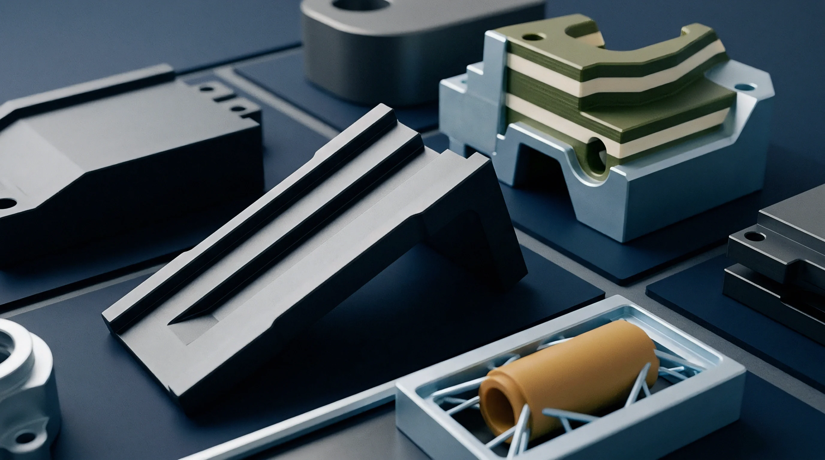
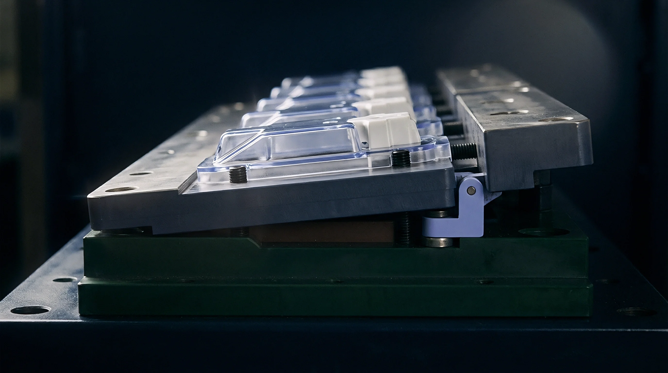
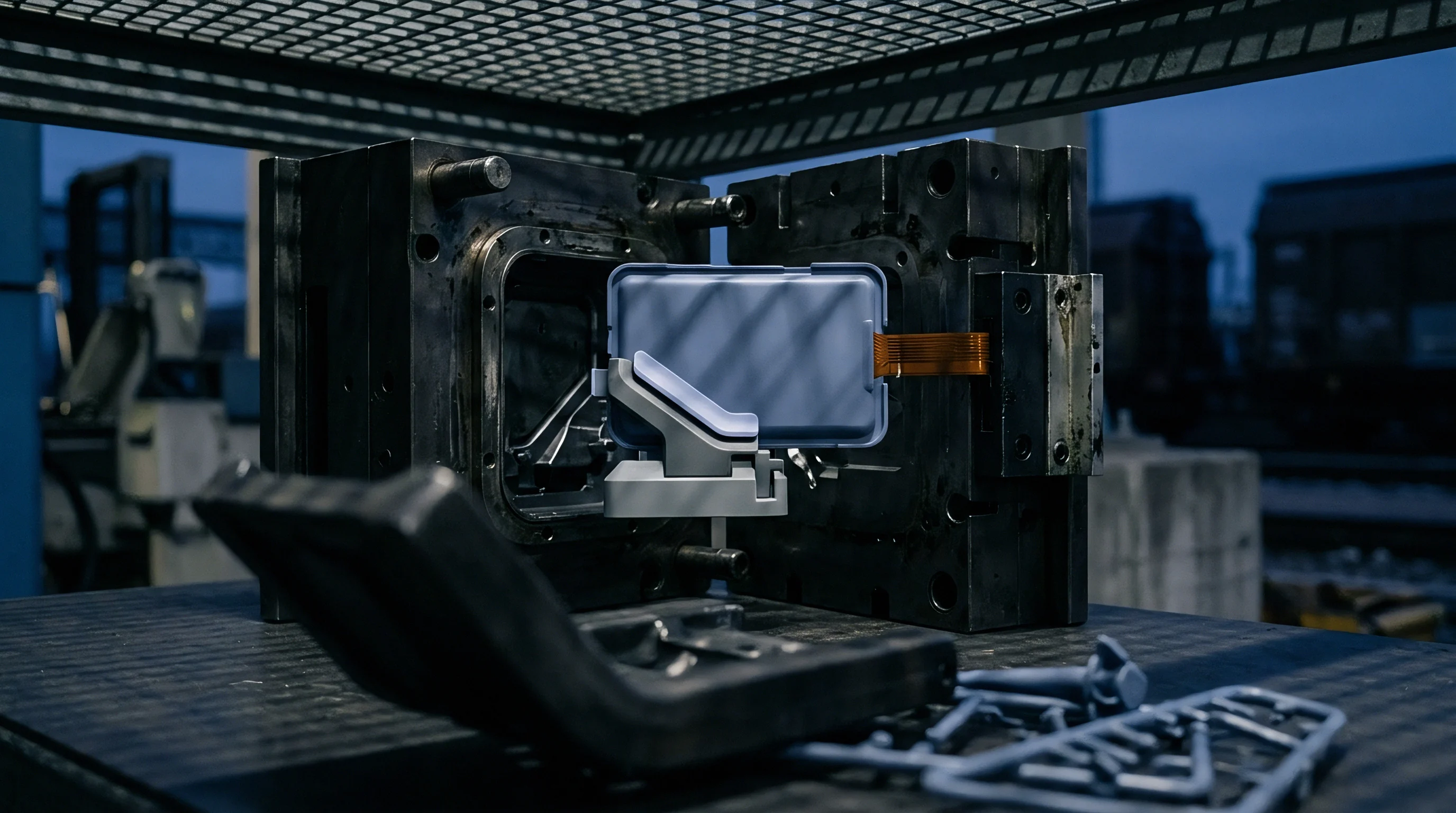
Designing high-wear regions as small, removable steel pockets isolates tool degradation to low-cost components. Gate regions, core tips, and parting line shut-offs degrade far faster than secondary cavity walls. Housing high-wear zones inside modular inserts crafted from CPM 10V steel limits expensive alloy usage to small volumes.
A solid cavity block constructed from standard H13 tool steel costs far less initially, but requires complete CNC remachining or EDM rebuilding when gate washout occurs. Modular inserts allow press-side replacement within hours, preserving continuous manufacturing output.
Worked Economic Sensitivity Analysis for Cavity Upgrades
Evaluating a four-cavity tool producing two million reinforced components demonstrates the financial impact of premium steel selection. An initial tool build using AISI H13 steel requires three scheduled gate insert rebuilds across the production lifecycle, incurring high maintenance labor and press downtime costs. Upgrading high-wear inserts to CPM 10V powder metallurgy steel increases initial tooling capital by four thousand dollars while running two million cycles without insert replacement.
The upfront premium amortizes to less than one-fifth of a cent per component, eliminating tens of thousands of dollars in unscheduled downtime and toolroom repair charges.
- Record baseline cavity quote using AISI P20 steel for a fifty-thousand shot production commitment.
- Calculate total steel replacement frequency when running thirty percent glass-filled nylon through unhardened inserts.
- Add toolmaker labor costs for three scheduled cavity insert replacements over a five-hundred-thousand shot tool life.
- Compare total lifetime maintenance outlay against the initial capital premium of vanadium powder metallurgy inserts.
Modular cavity construction isolates high-wear gate zones onto small interchangeable inserts, allowing toolmakers to restore original drawing dimensions within hours rather than remaking complete cavity blocks.