Real Time Melt Viscosity Monitoring and Part Dimensional Stability in Tooling
Real-time melt viscosity tracking decouples machine stroke from cavity dynamics, holding DIN 16742 tolerances across raw material batch shifts.

Shear
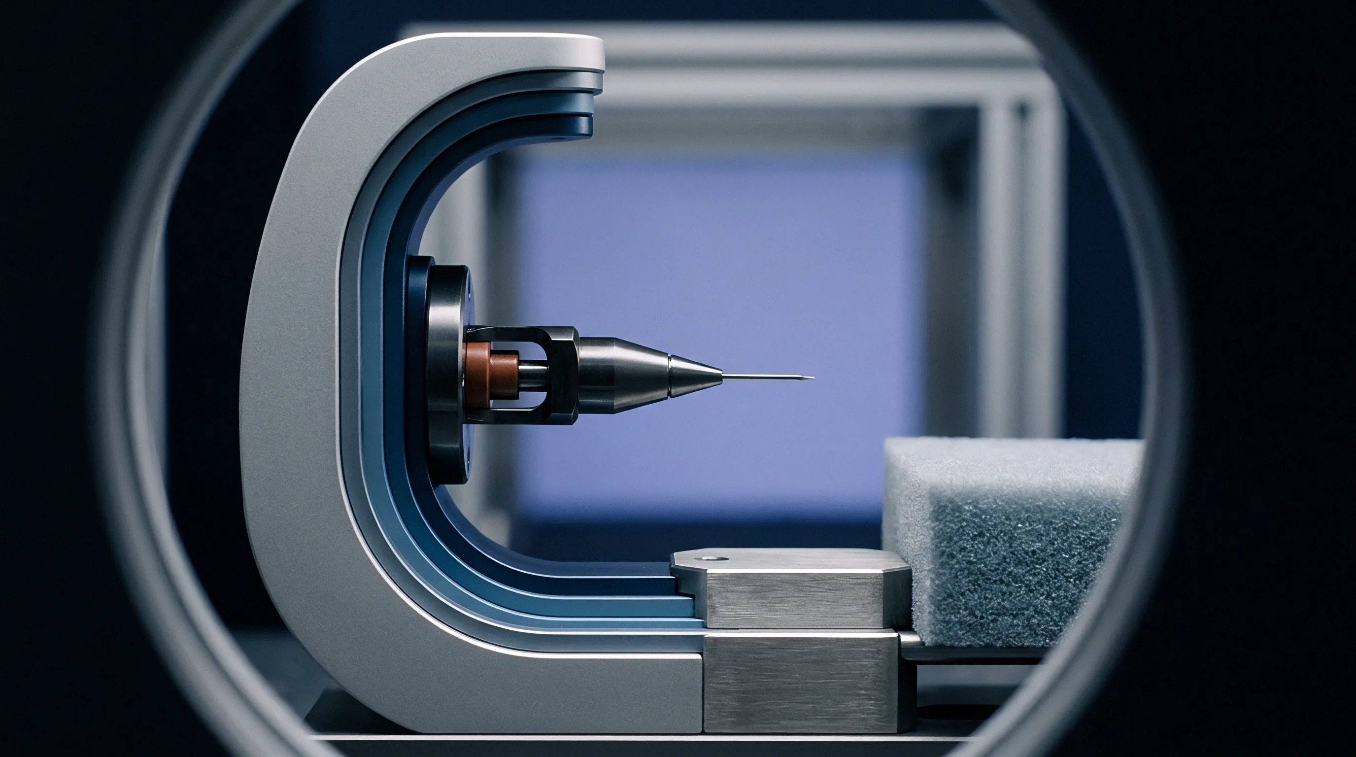
Polymer melt entering a runner system undergoes non-Newtonian thinning governed by the velocity gradient between the barrel center and the screw root. Resins exhibit variation in molecular weight distribution across lot deliveries, causing effective viscosity shifts under identical barrel setpoint temperatures. When material viscosity drops within the runner, the injection screw experiences lower resistance during velocity-controlled filling, advancing through stroke displacement faster than baseline settings predict.
This acceleration deposits an excess melt mass inside the cavity before the machine transfers control to packing pressure. A heavier shot packs out ribs and bosses beyond nominal tooling calculations, altering crystalline freeze rates and warping planar sections during cooling.
Injection units calculate apparent melt viscosity through the ratio of specific melt pressure to injection screw velocity during the filling phase. Screw stroke positions between twenty percent and eighty percent of volumetric fill establish an effective measurement interval, avoiding deceleration artifacts near the switchover boundary. The machine controller integrates the pressure-stroke curve to compute real-time viscosity indexes per cycle.
Variations exceeding five percent indicate thermal degradation, moisture exposure, or inconsistent regrind percentages blended at the hopper loader.
Viscosity increases lengthen filling time under constant hydraulic drive, lowering effective cavity pressure transmission prior to gate freeze.
Tooling cut for semi-crystalline materials relies on precise volumetric pressurization to maintain isotropic volumetric shrinkage. When melt viscosity climbs unexpectedly, the machine expends hydraulic pressure overcoming runner restriction rather than pressurizing cavity extremities. Outer dimensions shrink away from the cavity wall prematurely, generating internal voids and sink marks on cosmetic faces opposite structural ribs.

Viscous Dissipation across Variable Runner Geometries
Melt entering cold runner systems encounters severe shear heating through sub-millimeter gate restrictions. Viscous heating adds ten to twenty-five degrees Celsius locally to the resin stream, depending on gate velocity and thermal conductivity. An increase in virgin resin viscosity amplifies this shear-heating phenomenon, paradoxically reducing downstream resistance inside the cavity itself.
Machinists often adjust steel gate lands to manipulate shear stress, yet real-time press monitors register this behavior as an apparent drop in system resistance during the final fifth of volumetric fill.
Predictable gate freeze depends on thermal equilibrium between tool cooling channels and the shear-generated heat inside the melt. Lower viscosity lots generate minimal shear heat, freezing off earlier in the cycle and starving the cavity of packing mass. Higher viscosity lots generate elevated viscous dissipation, maintaining an open flow path that allows sustained pack pressure to over-compress the part core.
Thick gates preserve pressure transmission when melt resistance spikes, while narrow pin gates magnify lot-to-lot viscosity swings across production shifts.

Transducer
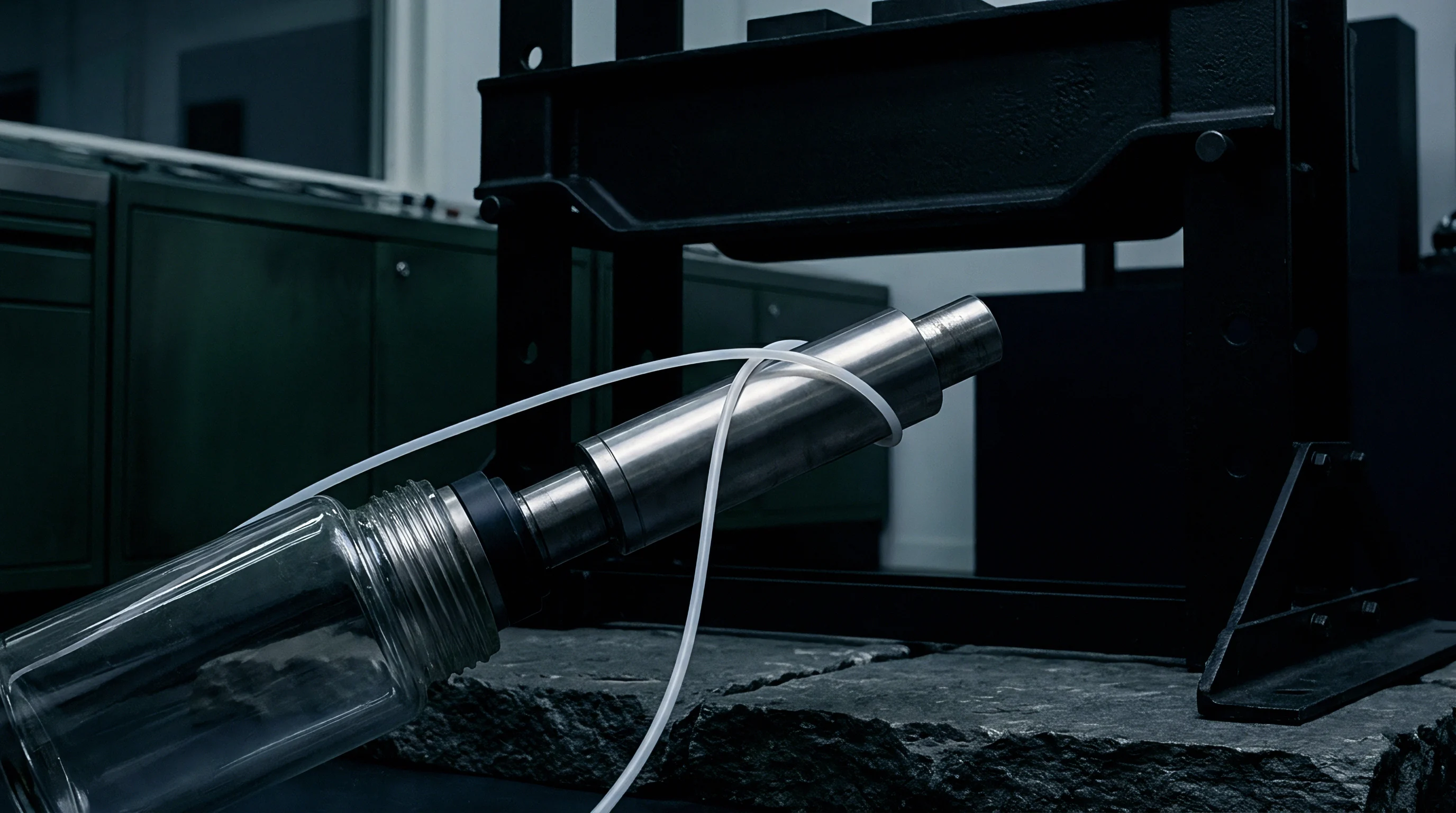
Direct cavity monitoring requires piezoelectric quartz sensors mounted behind ejector pins or flush with the mould wall along the flow path. Positioned near the gate, an initial sensor registers peak injection resistance, measuring the exact moment melt contacts steel. A second sensor placed at the end of fill registers arrival timing, revealing the true in-mould viscosity of the moving plastic front.
Calculating the differential pressure divided by the transit time yields the dynamic melt flow index directly inside the steel tool, eliminating screw slippage and check-ring leakage errors.
Check rings wear unevenly across production campaigns, permitting backflow over the screw flights during high-pressure injection phases. Standard machine barrel stroke monitoring misinterprets this backflow as forward melt injection into the tooling cavities. Direct wall pressure sensors decouple screw movement from cavity reality, exposing check-ring blow-by as an irregular pressure rise slope.
Tooling equipped with multichannel cavity telemetry catches volumetric deficit long before parts reach visual quality sorting benches.
| Sensor Location | Primary Metric Measured | Viscosity Drift Manifestation | Part Dimensional Outcome |
|---|---|---|---|
| Nozzle Bore Adapter | Specific melt pressure before sprue entrance | Pressure integral shifts during velocity stroke | Overall part mass variation across batch lots |
| Runner Post-Sprue | Effective shear rate entering runner branches | Premature pressure rise under low melt index | Incomplete fill in multi-cavity perimeter drops |
| Cavity Near-Gate | Peak packing pressure and gate freeze moment | Steep slope indicates high resistance batch | Thickness growth near gate, sink near boundary |
| Cavity End-of-Fill | Melt front arrival time and cavity seal pressure | Delayed arrival marks excessive melt resistance | Flash on late arrival, short shot on early freeze |
Ultrasonic sensing arrangements offer non-intrusive viscosity monitoring through tool steel without leaving sensor witness marks on cosmetic surfaces. Piezoelectric transducers mounted to the exterior tool plate transmit high-frequency sound waves through the mould block toward the cavity boundary. The reflection coefficient changes as plastic replaces air, while wave propagation speed through the polymer tracks density and thermodynamic state during pressurization.
Ultrasonic signatures correlate with instantaneous bulk modulus and shear behavior during the primary packing sequence.

Signal Integration and Data Acquisition Hardware
Charge amplifiers convert picocoulomb outputs from quartz elements into zero-to-ten-volt analogue signals sampled at kilohertz frequencies. Press controllers process these signals into deterministic metrics: maximum pressure slope, integral of cavity pressure over time, and time-to-peak. Digital interfaces pass these values directly to closed-loop controllers within milliseconds of injection completion.
Moulders occasionally claim incoming raw material meets all technical sheet requirements because certified melt volume rates match vendor bulk shipment paperwork.

Tolerance
Tool steel cavity dimensions remain physically static, whereas polymer dimensions vary according to thermal shrinkage coefficients and post-moulding crystallization kinetics. Standard drawing blocks call out DIN 16742 tolerance grades, typically Group 130 or Group 140 for unreinforced technical plastics. Holding a linear dimension within forty micrometers over a fifty-millimeter span demands cavity pressure consistency inside a two-bar window across every cycle.
Viscosity shifts upset this equilibrium by moving the internal pressure distribution away from nominal design parameters.
Unreinforced polyamides exhibit shrinkage rates between one and two percent parallel to flow, with transverse shrinkage often exceeding two point five percent. Variations in lot viscosity alter molecular orientation during the initial filling phase, changing this shrinkage ratio. A higher viscosity resin experiences greater molecular alignment under high shear, causing elevated longitudinal contraction and pronounced out-of-plane distortion upon cooling.
DIN 16742 Group 130 tolerance boundaries collapse when cycle pressure integrals shift past three percent of baseline.
Engineers calculate tooling shrink factors from empirical laboratory plaques pressed under static packing conditions. Real production tools experience differential cooling rates across core pulls, lifters, and slide faces. High-viscosity resin lots freeze quickly against chilled steel, developing a frozen layer that constricts subsequent flow.
The remaining liquid core cools under diminished pack pressure, creating an asymmetric stress profile across the wall section.
| Polymer Chemistry | Nominal Shrinkage Rate | Viscosity Offset Condition | Achieved Tolerance Range | Primary Geometry Defect |
|---|---|---|---|---|
| PA66 GF30 | 0.40 percent parallel, 0.90 percent transverse | Plus fifteen percent relative viscosity | DIN 16742 Group 130 | Differential warp across rib matrix |
| Polycarbonate Optical | 0.65 percent isotropic | Minus ten percent relative viscosity | DIN 16742 Group 120 | Parting line flash, lens birefringence |
| POM Copolymer | 2.10 percent isotropic | Plus twenty percent relative viscosity | DIN 16742 Group 140 | Pin boss diameter shrinkage below limit |
| PBT Unfilled | 1.80 percent isotropic | Minus twelve percent relative viscosity | DIN 16742 Group 130 | Linear sink mark on A-surface opposite ribs |
Variations across cavity sets create multi-cavity tooling challenges. An eight-cavity tool running naturally balanced runners will unbalance when processing batches of differing viscosity. Shear rates vary slightly across individual runner bifurcations due to minor manufacturing variations in runner steel geometry.
High-viscosity resin magnifies these geometric discrepancies, delivering unequal flow volumes to distal cavities.
Tooling that fails to regulate cavity pressure against viscosity fluctuations yields assemblies with mismatched snap fits, jammed slide mechanisms, and leaking gasket channels.
Switchover
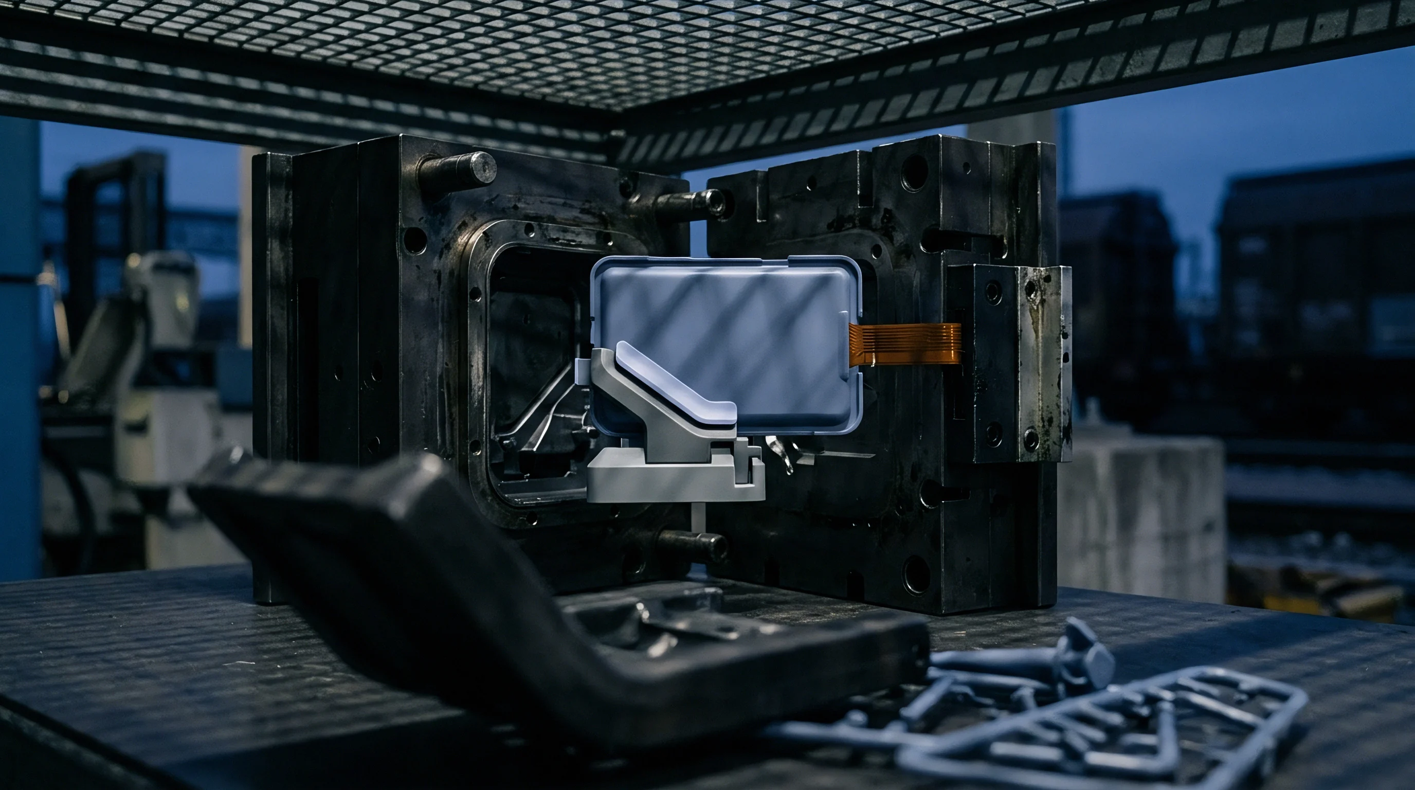
Controllers initiate packing pressure transfer through position, hydraulic pressure, cavity pressure, or elapsed injection time. Position-based changeover represents the conventional industrial baseline, switching control when the screw tip reaches a defined cushion point. This strategy functions reliably only when resin viscosity remains stable across cycles.
If material viscosity rises, the press expends excessive pressure during the filling stroke, reaching the changeover position with reduced melt velocity and degraded momentum.
Dynamic transfer systems monitor nozzle pressure gradients in real time, calculating the instantaneous work delivered to the melt stream. When incoming viscosity increases, the machine controller detects the elevated pressure integral early in the stroke. Advanced systems modulate the switchover position automatically, compensating for resin resistance by advancing the transfer stroke forward or holding higher velocity profiles deeper into cavity fill.
- Baseline Calibration establishes reference injection pressure profiles using virgin resin lots verified against capillary rheometer standards.
- Velocity Curve Tracking measures real-time screw hydraulic force continuously between ten and seventy percent of total volumetric shot travel.
- Dynamic Cutoff Compensation advances the position setpoint forward when viscosity registers high, preventing premature volumetric freeze inside runner branches.
- Cavity Pressure Transfer triggers packing mode precisely as the melt front contacts the end-of-fill transducer, independent of screw position.
Cavity-pressure-driven switchover insulates part geometry from lot variation more effectively than barrel metrics alone. An end-of-fill sensor trips transfer control precisely when plastic reaches cavity capacity, accommodating batch viscosity shifts without producing flash or underfill. The injection cylinder transitions to packing without relying on assumptions regarding check-ring seating repeatability.
Packing phase duration determines the final frozen part mass. Thick wall sections require extended pressure holding to feed volumetric shrinkage as resin transitions from liquid to solid state. Real-time viscosity measurements allow dynamic pressure profiling during holding, applying higher pack pressure to dense melt and reduced pressure to low-viscosity batches.
Melt compressibility averages half a percent per one hundred bar of applied hydrostatic holding pressure.
ISO 20457 defines standard operational boundary parameters for injection moulding production cells, binding suppliers to maintain documented process control windows across production contracts.

Yield
Scrap rates climb rapidly when tools run unattended during night shifts without automated viscosity compensation. A tool running forty-second cycles across a sixteen-cavity frame generates one thousand four hundred and forty parts per machine hour. When incoming resin viscosity swings five percent, unmonitored tools produce out-of-spec dimensions across entire shift runs before morning metrology benches flag the deviation.
Tool wear accelerates simultaneously as operators apply excessive packing pressure to force viscous plastic into stubborn cavity extremities.
Cavitation decisions define the commercial risk profile of precision tooling projects. High cavitation tooling magnifies the cost of process instability, compounding maintenance expenses when unbalanced cavities flash or gall sliding cores.
- Gate Erosion Rates accelerate when processing high-viscosity abrasive compounds, expanding steel orifices by fifteen micrometers over two hundred thousand cycles.
- Parting Line Hobbing occurs when excessive packing pressure drives mold halves apart, exceeding machine clamp tonnage and crushing parting surfaces.
- Core Deflection Damage bends thin shut-off pins as unbalanced viscous melt fronts apply asymmetric hydraulic side loads during high-speed injection.
Machining hardened steel cavities to nominal print dimensions leaves zero margin for material rheology fluctuations. Progressive toolmakers cut core pins slightly oversize and cavity walls slightly undersize, maintaining steel-safe conditions for future adjustments. Integrating real-time melt monitoring into the initial tool qualification phase verifies whether steel modifications are genuinely warranted or if dimensional drift stems from unregulated batch viscosity.
Suppliers track tool amortisation against clean cycle counts, yet tool depreciation accelerates when high packing stresses induce thermal fatigue cracking across sharp internal corners. Cavities running under closed-loop viscosity control maintain stable peak pressure profiles, doubling tool life spans and preserving dimensional repeatability over millions of cycles.
What remains undetermined is the degree to which ultrasonic cavity monitoring will replace physical quartz pressure transducers in high-cavitation production tooling over the coming decade.