Process Window Expansion Strategy for Glass Filled Polymer Dimensional Control
Expanding process windows for glass-filled polymers requires decoupling fill from pack pressure and controlling gate freeze to manage anisotropic shrinkage vectors.


Melt
Polyamides reinforced with thirty percent glass fibers exhibit complex rheological shifts when exposed to excessive shear rates inside the injection barrel. The addition of rigid glass strands changes the polymer matrix from a purely pseudoplastic fluid into a non-Newtonian suspension where shear viscosity depends heavily on screw rotational speed and injection rate. Processing glass-filled compounds within a stable dimensional window requires holding shear rates below the threshold where mechanical fiber fracture occurs.
High shear destroys fiber length. When average fiber length drops below the critical reinforcement threshold of approximately 150 micrometers for polyamide grades, stress transfer between the polymer matrix and the glass fibers breaks down, causing unpredictable post-mould shrinkage spikes.
Barrel temperature profiles must be stepped progressively from the feed zone to the nozzle to prevent premature resin degradation while maintaining uniform melt enthalpy. Heat drives polymer chain scission. Excessive residence time inside the barrel causes thermal degradation of the polymer chains, which alters the melt flow index during production runs.
A shift in melt flow index directly alters cavity pressure transmission, shifting the physical dimensions of the moulded part away from the nominal tool drawing targets.
Polymer Degradation Mechanics
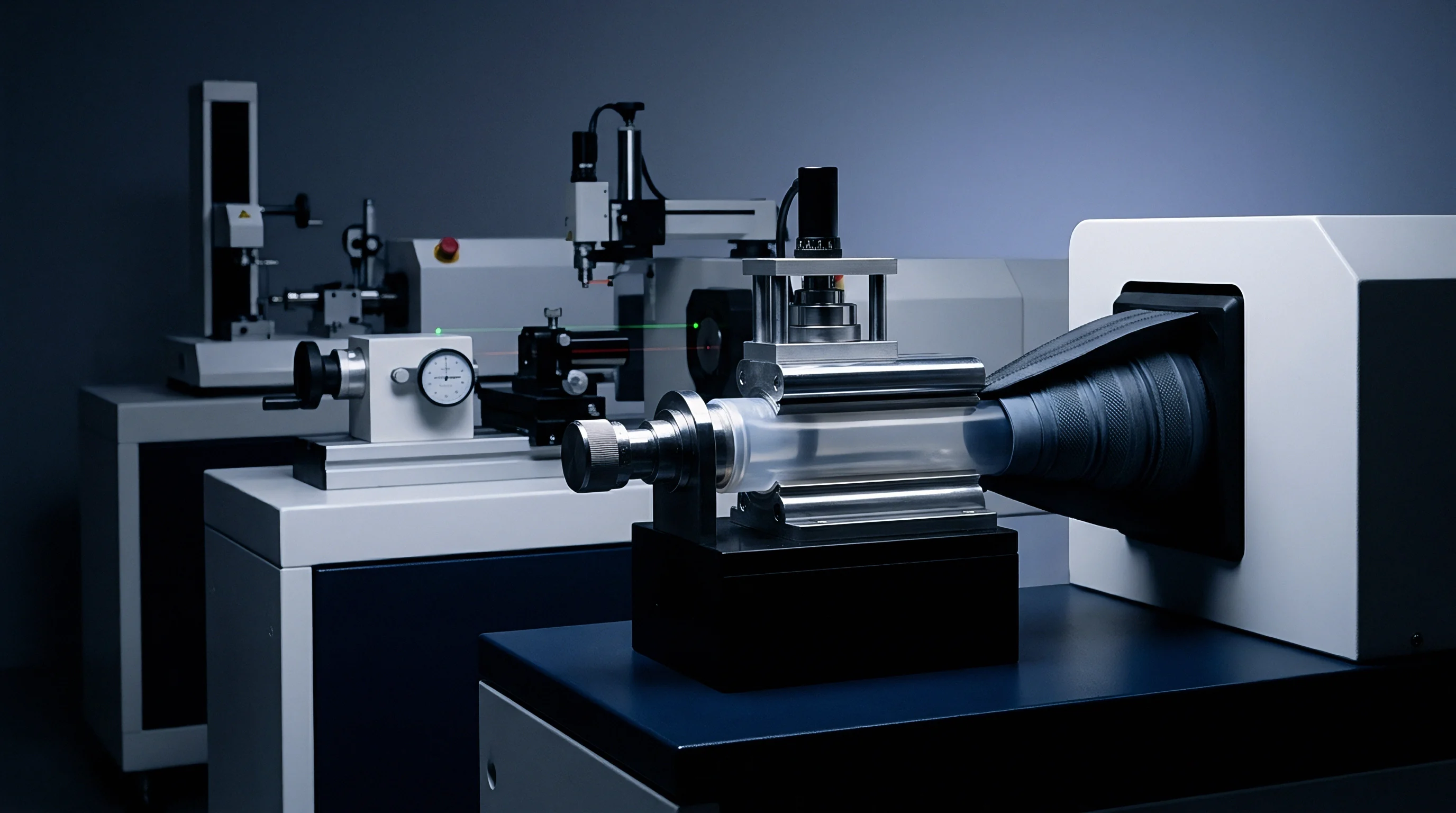
Thermal decomposition alters molecular weight distributions during prolonged heating cycles. Moist polymer pellets subjected to elevated processing temperatures undergo rapid hydrolytic degradation, which cleaves the amide linkages in polyamides and reduces the intrinsic viscosity of the matrix. Moisture thresholds prior to moulding ought to remain strictly under 0.04 percent weight by weight for polyamide 66 and below 0.02 percent for polybutylene terephthalate to prevent matrix embrittlement and dimensional instability.
Screw design plays a controlling role in preventing fiber degradation during the plasticization phase. Low compression ratio screws with deep flight depths reduce mechanical attrition on glass fibers during metering. Barrel back pressure kept between 3 and 7 MPa helps homogenize the melt temperature without generating destructive shear forces that shorten the reinforcement fibers.
Viscosity Curve Stabilization
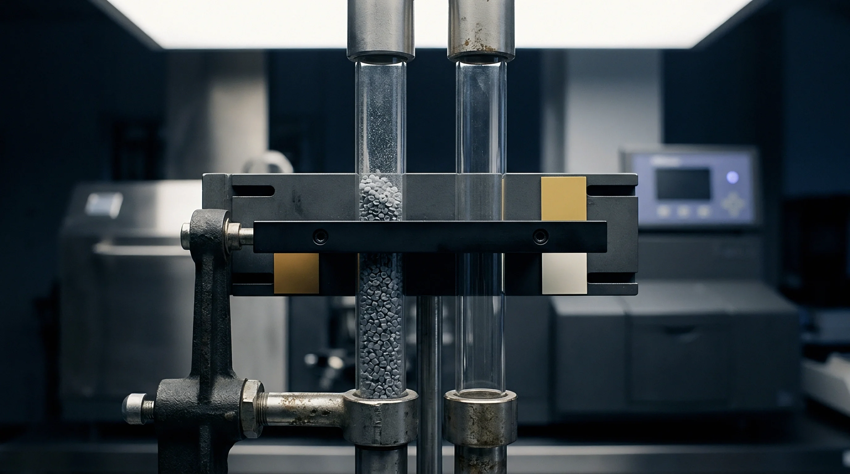
Rheological audits establish injection velocity boundaries across varying shear stress states. Running a viscosity curve trial by injecting material at incremental speeds from 10 millimeters per second to 160 millimeters per second identifies the flat Newtonian plateau where viscosity shifts become minimal. Operating within this plateau protects the moulding process against minor pressure variations on the factory floor.
| Resin Designation | Glass Weight (%) | Max Shear Rate (s⁻¹) | Max Barrel Residence (min) | Moisture Limit (% w/w) |
|---|---|---|---|---|
| PA66-GF30 | 30 | 40000 | 8 | 0.04 |
| PBT-GF30 | 30 | 35000 | 6 | 0.02 |
| PPS-GF40 | 40 | 30000 | 10 | 0.02 |
| PPA-GF50 | 50 | 25000 | 5 | 0.03 |
Material suppliers frequently maintain that batch-to-batch viscosity shifts within a ten percent band fall inside standard manufacturing specifications, shifting the burden of dimensional adjustment back onto press adjustments.


Orientation
Fountain flow mechanics force short glass fibers to align along parallel flow lines near the cavity boundary while creating transverse alignment in the central core. This classic skin-core-skin microstructure causes anisotropic physical properties throughout the moulded part. The outer skin layer, comprising roughly fifteen percent of the local wall thickness on each side, experiences high shear stresses during flow front propagation, leading to high fiber alignment in the direction of flow.
Fiber breakdown degrades structural integrity.
The central core experiences extensional flow during cavity filling, forcing glass fibers to reorient perpendicular to the primary flow vector. Core fibers align crosswise. This structural divergence causes linear thermal expansion and volumetric mold shrinkage to vary significantly based on directional measurement vectors.

Skin Core Microstructure Dynamics
Velocity profiles across the wall cross-section govern the relative depth of shell and core zones. Fast injection rates form thin skin layers and widen the central core zone, whereas slow injection rates allow the solidifying shell layer to grow inward, increasing parallel fiber orientation. Controlling wall thickness uniformity prevents local flow front acceleration that disrupts this microstructural balance.
Fibers aligned parallel to the flow vector exhibit one-third the thermal expansion coefficient of transverse core fibers.
Wall thickness variations greater than ten percent introduce local stress concentrations and velocity gradients. These gradients force the core layer to shift off-center, producing asymmetric stress distributions across the part cross-section upon cooling.
Gate Geometry Influences
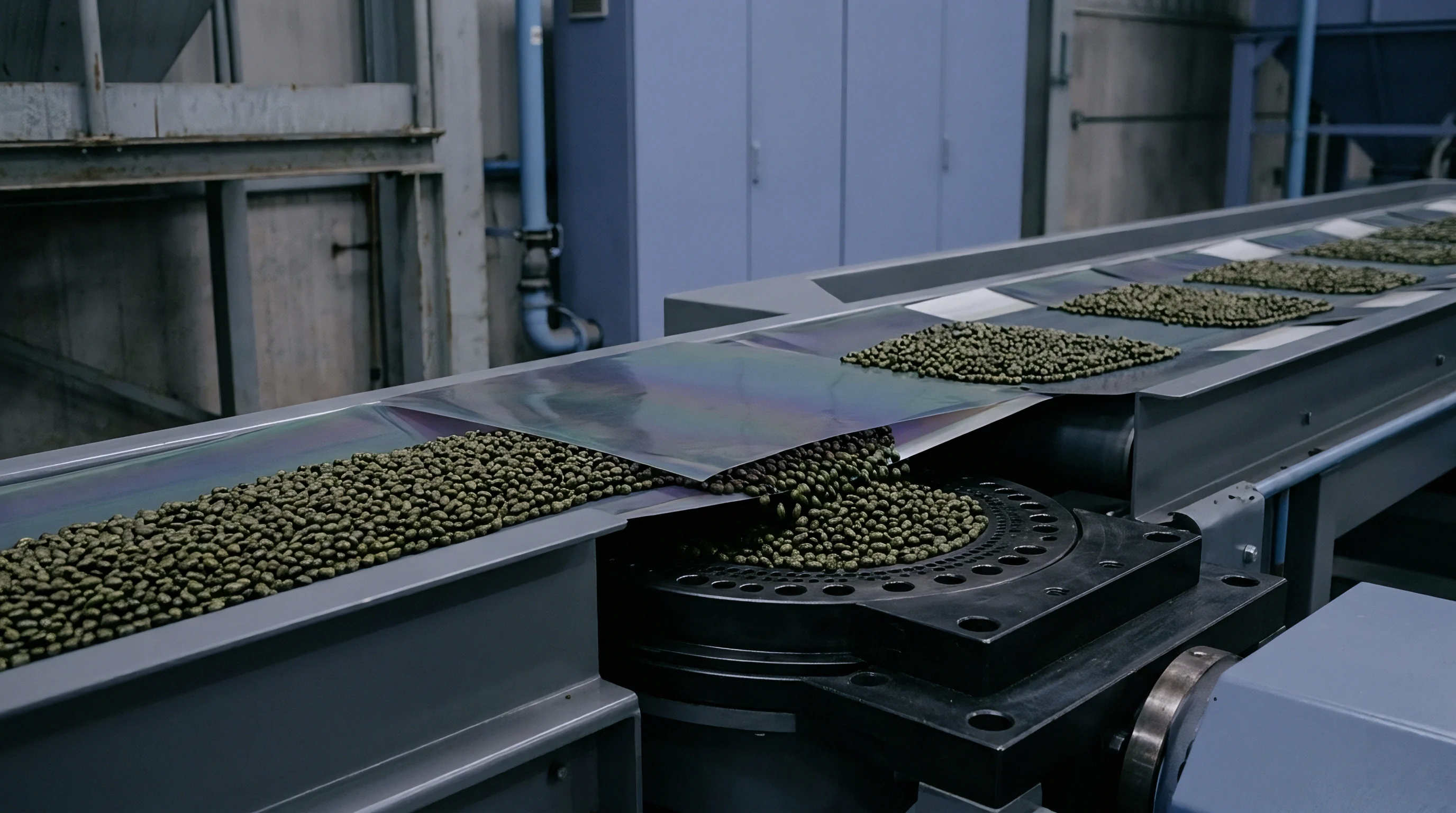
Tooling entrance dimensions alter fiber shear breakdown and initial jetting behavior inside the pocket. Pinpoint gates and small submarine gates create localized shear hotspots that degrade glass fiber lengths down to under 100 micrometers, destroying the mechanical reinforcement envelope. Submarine gate lands ought to feature generous cross-sectional areas to minimize shear stress during gate passage.
Fan gates spread the polymer flow front uniformly across broad flat geometry sections, establishing parallel flow lines and suppressing radial flow patterns. Radial flow fields generated by central sprue gates create circular orientation patterns that lead to severe dish-shaped warpage on disc geometries.
Thicker wall sections enlarge the transverse core zone, increasing isotropic tendencies at the expense of linear tensile modulus.


Cavity
Transducer signals placed near the end of fill reveal real-time pressure transfer efficiency during the transfer from injection to packing. Scientific injection moulding relies on Decoupled II or Decoupled III methodologies to decouple volumetric fill rate from hydraulic hold pressure. The high-speed injection phase fills ninety-five percent of the tool volume under stroke control, leaving the remaining volume to be packed out under precise cavity pressure regulation.
Sensor placement dictates feedback accuracy. Placing quartz piezoelectric sensors directly behind ejector pins located near the gate and at the last area to fill allows the press controller to track real-time pressure drops across the flow path.

Pressure Transfer Loss Profiles
Hydraulic pressure exerted at the screw tip drops substantially before reaching remote geometry features. Viscous resistance through small runner diameters and narrow gate orifices consumes a large fraction of the available machine injection pressure. As the polymer shell solidifies against cold tool walls, the effective cross-sectional flow channel narrows, accelerating pressure drop across the runner system.
Pressure drops across long runners. Holding pressure must overcome this dynamic wall-freezing effect to deliver material into the shrinking core section until gate seal occurs.
Decoupled Moulding Phase Transitions
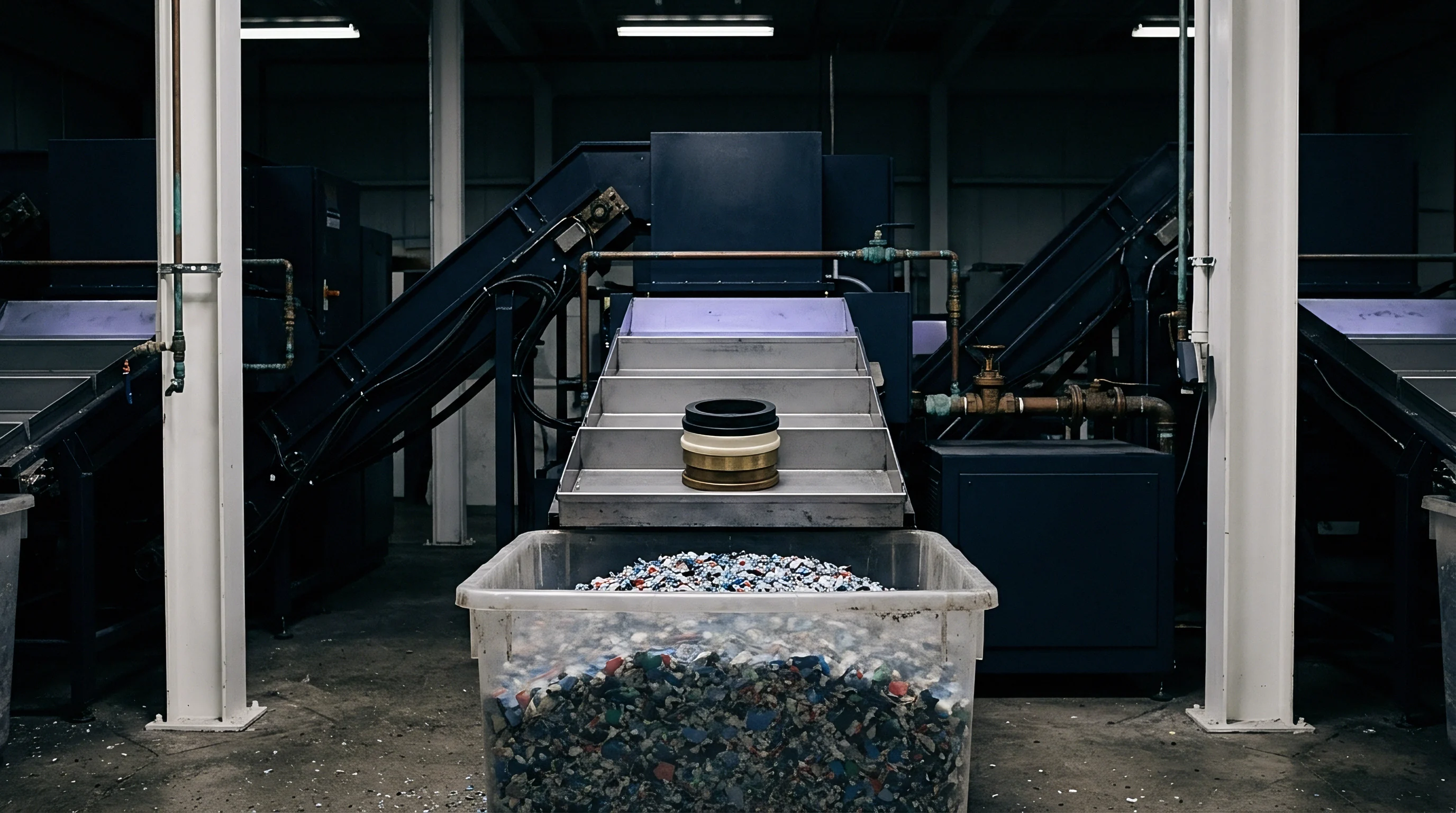
Physical decoupling separates high-speed fill velocity from steady hydraulic packing. Transferring from fill to pack based on cavity pressure thresholds eliminates part weight variation caused by batch-to-batch material viscosity shifts. Gate freezing seals cavity pressure.
- Sink Mark Formation occurs when pack pressure drops prematurely before gate freeze.
- Flash Generation develops when peak cavity pressure exceeds machine clamp tonnage.
- Dimensions Undersized manifest when hold pressure duration terminates prior to gate solidification.
- Internal Voiding originates from thick section vacuum formation during uncompensated cooling.
DIN 16742 Tolerance Group TG4 applies only when cavity pressure variations remain under two percent across the production lot.
Failing to compensate for hydraulic pressure drops across long flow channels leads to sink marks and non-conforming part dimensions that force premature scrap sorting.


Warp
Differential shrinkage vectors between flow parallel directions and flow transverse directions generate residual internal stresses that distort unconstrained part geometries. Glass-filled polymers exhibit isotropic volumetric contraction in the unreinforced matrix state, but glass orientation blocks shrinkage along the fiber longitudinal axis. Transverse shrinkage typically runs three to four times higher than longitudinal shrinkage in thirty percent glass-filled polyamide 66 components.
Thermal gradients drive residual stress. Variations in mold surface temperature between the fixed side and moving side of the tool cause asymmetric cooling rates across the part thickness, compounding the dimensional distortion caused by fiber orientation anisotropy.
Anisotropic Shrinkage Vector Balancing
Volumetric contraction rates in thirty percent glass-filled polyamide 66 range from 0.3 percent along flow lines to 1.1 percent across flow lines. Differential cooling bends flat geometry. Part design rules must account for this directional divergence by orienting primary critical tolerances parallel to the anticipated fill pattern.
Core and cavity cooling circuits must be engineered with independent temperature control loops. Operating the core circuit at a lower temperature than the cavity side can counteract thermal bowing by inducing compensating bending moments within the cooling solid shell.

Which Processing Factors Expand Mechanical Process Windows?
Mould surface temperatures elevated to 90°C promote polymer crystallization uniformity while reducing residual internal stresses. Higher mold temperatures extend the cooling cycle slightly but yield parts with greater dimensional stability over their service life. Lower mold temperatures freeze in high stress levels, leading to post-mould warping when parts are exposed to elevated operating temperatures.
| Process Variable | Baseline Value | Expanded Boundary | Parallel Shrink (%) | Transverse Shrink (%) | Flatness Distortion (mm) |
|---|---|---|---|---|---|
| Mold Temp (°C) | 60 | 95 | 0.28 | 0.85 | 0.42 |
| Hold Pressure (MPa) | 50 | 85 | 0.31 | 0.72 | 0.28 |
| Injection Speed (mm/s) | 30 | 110 | 0.25 | 0.98 | 0.55 |
| Melt Temp (°C) | 275 | 295 | 0.30 | 0.88 | 0.36 |
A twenty degree Celsius increase in core mold temperature reduces transverse flatness deviation by 0.35 mm on a 150 mm structural plate.
Engineers continue to debate whether gate positioning or cooling circuit velocity plays the dominant role in minimizing long-term creep-induced distortion in high-temperature environments.


Envelope
Dimensional control strategies demand structured parameter mapping to establish upper and lower boundary limits for acceptable part tolerances. Design of Experiments execution maps the interplay between melt temperature, mold temperature, injection velocity, and pack pressure, defining the operational window inside which parts comply with engineering drawings under ISO 20457 capability standards.
Tight tolerances demand strict process windows. Broadening this operating envelope allows the moulding press to absorb minor environmental fluctuations, machine wear, and material lot variance without yielding non-compliant parts.

Design of Experiments Parameter Boundaries
Statistical screening designs evaluate melt temperature, mold temperature, injection speed, and pack pressure against tight engineering specifications. Response Surface Methodology constructs quadratic model surfaces that pinpoint the center of the acceptable process window. Operating near the geometric center of this envelope prevents minor thermal drift from pushing dimensions beyond critical specification limits.
Machine wear shifts fill rate. Hydraulic valve response drift and screw check-ring leakage alter volumetric fill repeatability, making continuous sensor monitoring essential for maintaining process position inside the optimized parameter window.

Multi Cavity Tolerance Stack Allocation
Runner volume balance across multi-pocket tooling determines dimensional capability distribution. Imbalances in flow length or runner diameter cause pressure differences between inner and outer cavities, producing dimensional variation across parts moulded in the same cycle shot.
- Measure runner pressure drop across each cavity using identical sensor positions during dry fill.
- Adjust gate orifice diameters using electrical discharge machining to balance volumetric flow within one percent.
- Set up baseline cavity pressure traces across all pockets under nominal process settings.
- Shift pack pressure in five percent increments to plot the lower limit of sink formation against the upper limit of parting line flash.
- Document the resultant dimensional Cpk values across fifty continuous cycles per cavity stream.
Contractual quality agreements invoking ISO 20457 Grade NW tolerances mandate that process parameter shifts remain within documented Design of Experiments boundaries during serial production.


Yield
Tooling investment decisions hinge on balancing cavity counts against unit piece prices and dimensional capability statistics. Higher cavitation lowers machine hour costs per part but narrows the effective process window due to thermal and pressure distribution variances across the tool face. Steel modification remains expensive after hardening.
Tooling budgets must accommodate the cost of core and cavity modification during initial tool tuning trials. Adjusting steel dimensions after analyzing first-shot shrink rates allows toolmakers to center part dimensions within nominal drawing bands.

Tooling Amortization and Cavitation Scenarios
Capital allocation for a four-cavity hot runner mold demands continuous press utilization to achieve target return rates. Two-cavity tools offer broader operational windows and lower upfront tooling costs, making them optimal for low-to-medium production volumes where dimensional tolerances remain tight.
| Cavitation Count | Initial Tool Cost (USD) | Cycle Time (s) | Machine Rate (USD/hr) | Unit Tool Cost at 100k (USD) | Landed Piece Price (USD) |
|---|---|---|---|---|---|
| 2 Cavities | 45000 | 22 | 65.00 | 0.45 | 1.05 |
| 4 Cavities | 78000 | 24 | 85.00 | 0.78 | 1.13 |
| 8 Cavities | 135000 | 26 | 110.00 | 1.35 | 1.59 |
| Calculations assume a production target of 100,000 units, 95% plant efficiency, and PA66-GF30 material cost of $4.20/kg. | |||||

Production Lot Acceptance Verification
Quality inspection protocols rely on statistical sample sizing to clear completed production lots. Statistical process control tracks key feature dimensions across shift changes, generating real-time capability metrics that trigger process halts before non-conforming parts enter the shipping dock.
- Dimensional Cpk Index confirms that critical feature tolerances achieve a minimum statistical capability threshold of 1.33 across thirty consecutive shots.
- Fiber Degradation Analysis verifies that burnoff testing retains an average glass length exceeding 250 micrometers.
- Moisture Content Verification measures residual moisture below 0.04 percent prior to processing using Karl Fischer titration.
- Parting Line Flash Inspection confirms zero flash protrusion exceeding 0.05 millimeters along critical sealing faces.
Production shifts operating outside verified process windows increase scrap rates by up to twelve percent on glass-filled PPA components.
Serialized lot traceability records link machine cavity pressure files to final inspection measurements. When dimensional drift occurs during continuous night shifts, press operators retrieve historical sensor traces to isolate hydraulic instability from raw material batch variance.