Modelling Thread Flank Stress Relaxation in Glass Reinforced Molded Bosses
Glass-reinforced thread flank relaxation depends on fiber orientation mapping and viscoelastic Prony models to prevent clamp load decay in molded bosses.

Flank
Threaded fasteners in glass-reinforced polymers exert severe localized hoop and axial compression against internal helical grooves. Driving a thread-forming screw into a molded boss creates elastic deformations alongside permanent plastic flow in the matrix. Peak contact stresses regularly exceed eighty megapascals at the primary thread crest engage points.
Contact pressure drops rapidly. Over prolonged exposure, the polymer chains reorient under this localized shear field. The embedded glass filaments maintain their stiff response, but the surrounding thermoplastic matrix relaxes, causing a measurable drop in clamp force across the joint assembly.
Quantifying this force decay requires examining the contact geometry between fastener and molded flank. Thread geometry converts axial bolt tension into radial expansion force against the boss wall. Standard thread flank angles of thirty degrees induce tangential hoop stress concentrations that exceed nominal axial stress by a factor of two.
Matrix relaxation under high radial tension allows the internal thread profile to yield radially outward, reducing contact pressure along the flank face.
Contact Stress Distribution
Thread lead angles generate complex triaxial load fields across engaged mating helical surfaces. The highest normal stresses occur at the first two engaged thread pitches, carrying over sixty percent of the total clamping load. Contact pressure distribution across the thread flank is far from uniform, peaking sharply at the thread root fillet and tapering toward the tip.
High hoop stress induces crazing. Matrix deformation causes the thread flank profile to conform to the steel fastener face over initial assembly hours, expanding contact surface area while reducing peak stress magnitude.
Polyamide 66 reinforced with thirty percent glass fibers loses up to thirty-five percent of its initial thread contact pressure within one hundred hours at eighty degrees Celsius.

Viscoelastic Decay Mechanisms
Polymer matrices undergo progressive rearrangement under continuous static load while embedded fibers remain elastic. Viscoelastic creep and stress relaxation occur simultaneously inside the loaded boss region. Primary creep occurs immediately after fastener driving, characterized by high strain rates as amorphous polymer regions realign.
Secondary creep proceeds at a lower, steady-state rate governed by molecular chain slippage and thermal energy levels. Matrix shear drives the decay. Elevated temperatures accelerate matrix relaxation rates according to time-temperature superposition dynamics, reducing the effective modulus of the composite matrix over operational service life.

Fiber Glass Orientation Impact
Filler geometry alters local creep compliance along orthogonal coordinate axes. Glass fibers act as elastic rigid inclusions within the viscoelastic matrix, constraining matrix mobility along their longitudinal axis. Fibers aligned parallel to the thread flank surface resist sliding, reducing shear compliance and limiting local relaxation.
Fibers oriented perpendicular to the contact face offer negligible constraint against normal compressive relaxation, allowing the matrix to creep laterally into microscopic flank voids. Cold flow reduces clamp force. Anisotropic mechanical properties dictate that local relaxation moduli differ drastically across the boss wall thickness.
Ignoring thread flank creep leads directly to field fastener loosening, housing oil leaks, and complete warranty rejection during high-vibration qualification.
Orientation
Melt shear fields inside annular tool cavities dictate how reinforced filaments line up during injection. Molten glass-filled resin flowing into a cylindrical boss split around the central core pin, creating distinct fiber orientation zones across the wall section. High shear rates near the mold wall and core pin surface align fibers parallel to the flow direction, creating an anisotropic skin layer.
The central core region experiences lower shear rates and higher transverse elongation, resulting in random or circumferentially aligned fibers. Radial pressure expands the wall. The local mechanical response of the molded thread depends entirely on this cross-sectional fiber architecture.
Predicting fiber orientation requires coupling mold filling simulations with microscopic anisotropy models. Shear-induced alignment near the thread crests increases local tensile modulus along the helical pathway, but reduces shear modulus perpendicular to the flow. When thread-forming screws drive into the molded pilot hole, they cut or form threads directly through this heterogeneous fiber structure.
Weld lines solidify along the rejoining flow fronts, introducing weak mechanical planes where fibers align parallel to the seam rather than across it.
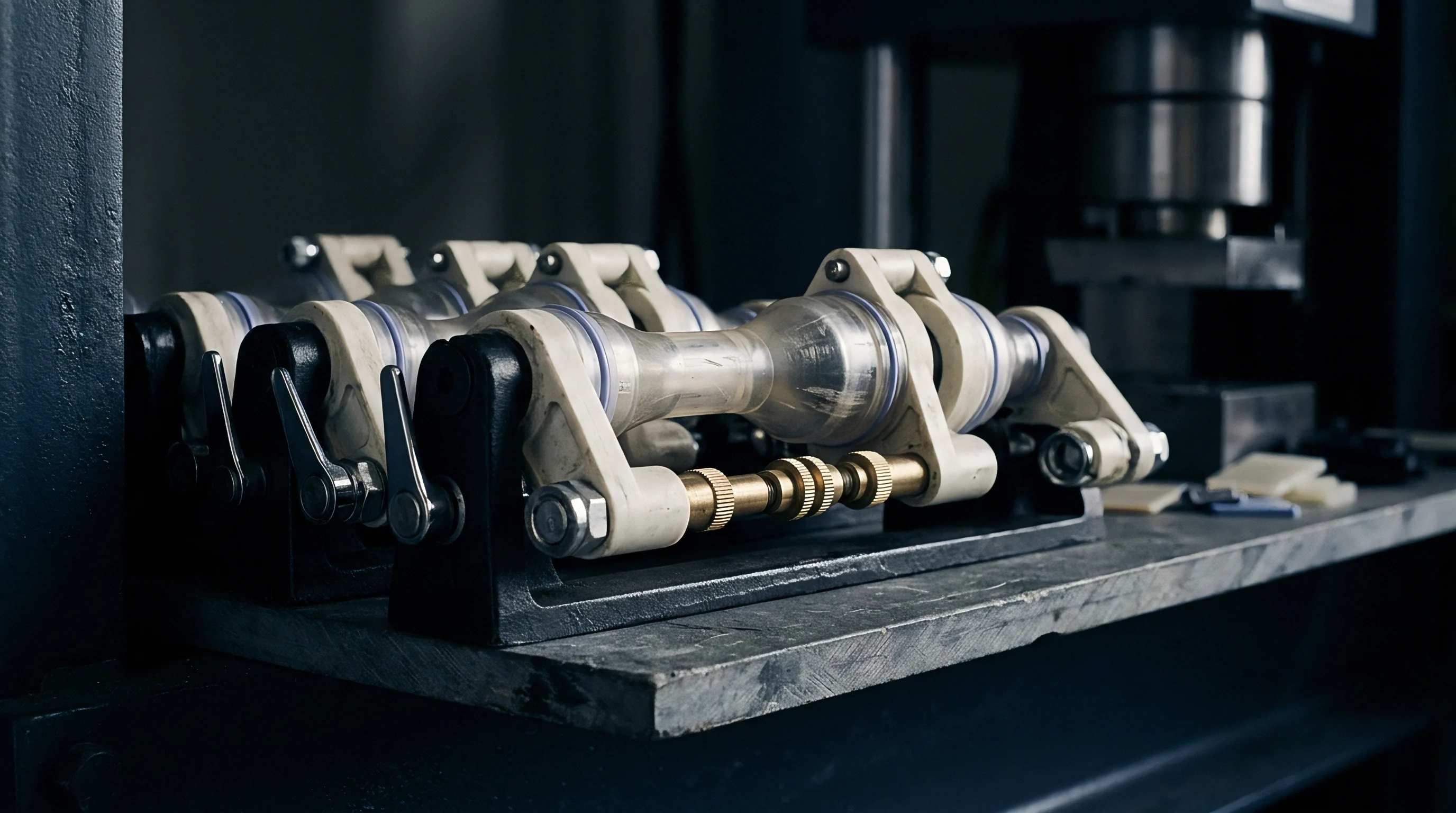
Flow Mechanics in Annular Cavities
Polymer fluid moving past a centered core pin splits into skin, shell, and core layers across the wall cross-section. Dynamic viscosity variations driven by cooling rates alter local fiber rotation rates during cavity fill. Near the cold steel surfaces of the core pin, quick thermal freezing traps fibers in high-shear alignment parallel to the pin axis.
In the mid-wall region, slower cooling allows fibers to align along circumferential flow lines created by advancing fountain flow fronts. Core pin deflection destroys symmetry. Gate location governs fiber alignment.
Asymmetric gate placement creates uneven velocity distributions around the pin, displacing the orientation core off-center and generating localized mechanical soft spots.
Fibers aligned perpendicular to the thread flank face permit up to three times greater compressive relaxation strain than fibers aligned parallel to the load axis.

Tensor Mapping Methods
Second-order orientation tensors quantify directional probability distributions across discrete finite element locations. Advani-Tucker orientation tensor formulations track fiber rotation resulting from velocity gradients inside the melt stream. The principal diagonal components of the tensor describe the statistical alignment probability along three orthotropic axes.
Weld lines weaken thread roots. Translating these spatial tensor values into structural material properties requires micro-mechanical homogenization schemes such as the Mori-Tanaka or Eshelby inclusion models, converting local fiber distributions into orthotropic viscoelastic stiffness matrices.
- Fiber-Matrix Debonding occurs when localized shear stress exceeds the interfacial adhesive bond strength between glass filaments and polymer matrix, accelerating micro-crack growth under sustained flank compression.
- Matrix Micro-Crazing forms under elevated hoop tensile stress near thread roots, reducing structural stiffness and accelerating localized creep relaxation.
- Weld Line Splitting develops along rejoining melt fronts where low cross-seam fiber alignment creates structural weakness under fastener radial pressure.
- Core Pin Displacement Yield arises when non-uniform injection packing pressure flexes the mold core pin, producing variable wall thickness and localized relaxation spikes.
Moulders frequently claim that standard isotropic finite element runs adequately bound safety factors, disregarding local fiber alignment near core pins.
Viscoelasticity
Time-dependent strain accumulation under constant load requires mathematical representation using mechanical analog networks. Classical elastic linear finite element analysis fails to capture long-term clamp load decay in plastic bosses because it ignores matrix time dependency. Viscoelastic constitutive formulations represent material response by combining elastic spring elements with viscous dashpot elements.
The Generalized Maxwell model, expressed as a Prony series, divides stress relaxation into a summation of discrete exponential decay modes, each defined by a characteristic relaxation time constant and material modulus parameter.
Characterizing glass-reinforced resins for relaxation modeling requires extensive dynamic mechanical analysis and tensile creep testing across operational temperature bands. Test data fitting determines Prony series coefficients across time decades ranging from seconds to thousands of hours. Because glass fibers remain purely elastic, the composite relaxation spectrum scales directly with matrix volume fraction and matrix thermal state.
Non-linear viscoelastic behavior emerges at elevated stress levels, requiring stress-dependent shift functions to account for accelerated relaxation under high flank contact pressures.

Generalized Maxwell Formulations
Spring and dashpot units arranged in parallel capture stress decay across multiple logarithmic time decades. The mathematical relaxation modulus function sums an equilibrium modulus with transient exponential decay terms. Measuring these parameters involves step-strain stress relaxation trials performed on standardized injection-molded specimens under controlled temperature regimes.
Glass fibers do not creep. The instantaneous modulus reflects unrelaxed elastic stiffness, while long-term equilibrium modulus defines material resistance after complete matrix stress dissipation.
| Polymer Matrix Grade | Test Temp (Deg C) | Instantaneous Modulus (MPa) | Equilibrium Modulus (MPa) | Primary Relaxation Time (s) | Modulus Loss 1000h (%) |
|---|---|---|---|---|---|
| PA66-GF30 (Dry) | 23 | 9500 | 6200 | 3.2e4 | 22.1 |
| PA66-GF30 (Conditioned 50% RH) | 23 | 6800 | 3900 | 1.1e3 | 38.5 |
| PA66-GF30 (Conditioned 50% RH) | 80 | 4200 | 1800 | 8.5e1 | 52.4 |
| PBT-GF30 | 23 | 8800 | 6100 | 5.4e4 | 18.3 |
| PBT-GF30 | 80 | 5100 | 2900 | 4.2e2 | 39.2 |
| PPA-GF40 | 120 | 11200 | 7800 | 1.8e3 | 26.7 |
Temperature and Time Superposition
Shift factors calculated from the Williams-Landel-Ferry equation translate elevated temperature test data to long-term service predictions. Above the glass transition temperature, structural polymers experience rapid mobility increases in amorphous chain segments. Thermal expansion accelerates relaxation rate.
Empirical horizontal shift factors collapse stress relaxation curves recorded at various elevated temperatures onto a single master curve at a reference operating baseline. This time-temperature equivalence enables simulation of multi-year operational clamp load loss using laboratory data generated over weeks.
Conformity with ISO 899-1 tensile creep standards requires continuous load monitoring across minimum one-thousand-hour test windows to validate non-linear viscoelastic shift factors.

Structural Mesh Mapping Protocols
Exporting localized fiber tensors into structural solvers converts isotropic finite element meshes into orthotropic constitutive domains. Coupling injection molding process software to structural stress packages involves mapping spatial fiber orientation arrays onto structural calculation grids. Interpolation algorithms transfer fiber density and directional vectors, generating localized material coordinate systems for every discrete element.
Thread engagement depth fixes load. Structural solvers then assign orthotropic Prony series properties aligned with local fiber orientation axes, enabling accurate prediction of thread flank relaxation under high assembly loads.
- Run injection molding filling and packing simulation using actual tool geometry, gate locations, and press processing parameters.
- Export spatial second-order fiber orientation tensors and volumetric shrink grids at full element density.
- Import part geometric mesh into structural finite element pre-processor and generate dense thread contact mesh refinement.
- Map orientation tensor data from process mesh to structural mesh using non-linear spatial interpolation algorithms.
- Assign orthotropic material properties using micro-mechanics homogenization models coupled to temperature-dependent Prony series parameters.
- Apply fastener driving torque simulation loads and solve time-dependent non-linear viscoelastic relaxation steps across specified thermal service cycles.
Uncertainty remains regarding whether high-frequency vibrational input accelerates micro-crack nucleation within the physical aging matrix at elevated temperature.
Boss
Cylindrical mounting features require precise geometric ratios to prevent premature burst failure during fastener installation. Outer diameter, pilot hole diameter, engagement depth, and internal draft angles directly govern local stress concentrations. Standard design practice specifies an outer boss diameter equal to two to two-and-a-half times the nominal screw diameter.
Wall section design must balance structural hoop stiffness against molding cycle efficiency. Excessively thick walls induce sink marks, internal voiding, and prolonged cycle times, while thin walls generate excessive hoop stress leading to stress rupture during fastener insertion.
Thread-forming screws displace polymer matrix material during driving, creating internal matching threads through local cold flow and mechanical cutting. Pilot hole taper resulting from core pin mold draft causes non-uniform engagement depth across the fastener length. Tight core cooling prevents sink.
At the top of the hole, larger internal diameter reduces thread engagement depth, lowering stripping torque. At the blind bottom, reduced diameter increases driving torque and radial expansion force, elevating localized matrix stress and accelerating creep relaxation.

Wall Thickness Ratios
Ratio choices between outer diameter and internal pitch diameter govern tangential stress magnitudes. Increasing wall thickness raises radial restraint against thread flank displacement, suppressing local viscoelastic creep. Yield strength drops when internal voids form due to improper wall transitions.
Tool thermal control limits voiding. Molded holes maintain orientation rings. Nominal wall thickness should match adjacent housing wall section within twenty percent to preserve uniform material cooling rates and prevent localized differential shrinkage.
| Boss Outer Diameter to Screw Diameter Ratio (D/d) | Pilot Hole Draft Angle (Degrees) | Initial Thread Engagement Depth (% Pitch) | Peak Radial Hoop Stress (MPa) | Calculated 1000h Relaxation Multiplier |
|---|---|---|---|---|
| 1.8 | 1.0 | 65 | 112 | 1.65 |
| 2.0 | 0.5 | 75 | 88 | 1.32 |
| 2.2 | 0.5 | 80 | 74 | 1.12 |
| 2.5 | 0.25 | 85 | 61 | 1.00 |
| 3.0 | 0.25 | 88 | 54 | 0.94 |
Weld Line Interaction at Thread Roots
Rejoining melt fronts form localized V-notches along interior fastener surfaces. Weld line locations experience poor fiber crossover, resulting in isotropic, matrix-rich zones with low tensile strength. When thread flank pressure exerts outward radial force, weld lines act as structural notch stress concentrators.
Fastener driving torque causes micro-fracturing along these weak seam lines, reducing engagement stiffness. Viscoelastic matrix flow expands these micro-cracks over time, causing accelerated clamp force decay and potential longitudinal wall splitting.

What Governs Thread Stripping Torque after Thermal Aging?
Thermal cycling weakens matrix shear resistance surrounding embedded glass fibers. Matrix relaxation along engaged thread flanks reduces interference fit pressure, directly decreasing friction torque resistance. Lower matrix modulus at elevated service temperatures permits thread crests to deform under axial tension, facilitating thread stripping during re-torque maintenance.
Torque limits prevent strip failure. Preserving stripping torque capacity requires optimizing core pin cooling channels to maximize local matrix crystallinity and minimize amorphous stress relaxation near thread roots.
- Outer Diameter Sizing dictates radial containment stiffness, requiring a minimum diameter ratio of 2.2 times fastener nominal diameter to suppress hoop relaxation.
- Pilot Hole Diameter Calibration sets thread engagement depth, requiring tight tolerance control to guarantee seventy-five percent minimum thread engagement along full drive length.
- Core Pin Draft Minimization limits engagement variation, keeping draft angles below 0.5 degrees per side to prevent bottom-hole stress concentration.
- Countersink Lead-In Chamfer guides fastener entry, preventing top-edge boss cracking and reducing initial driving torque spikes during thread cutting.
Designing boss wall thickness equal to screw outer diameter maintains sufficient hoop stiffness without introducing severe sink marks or internal voids.

Retention
Clamp force preservation over ten-year operational spans relies on accurate initial torque specification. Mechanical joint integrity depends on holding residual tension above minimum critical sealing levels. Fastener installation applies dynamic torque that converts into axial bolt clamp force and friction loss along thread flanks.
As the matrix under the thread flank relaxes, bolt stretch decreases, directly reducing joint clamp load. Initial seating torque must account for expected viscoelastic force losses without exceeding matrix ultimate tensile yield strength during installation.
Specifying initial seating torque requires comprehensive joint relaxation modeling that combines mechanical fastener stiffness, boss elasticity, and matrix creep functions. Over-tightening introduces high initial hoop stresses that accelerate non-linear relaxation rate, yielding lower long-term clamp force than a lower, properly calculated seating torque. Under-tightening provides insufficient initial stretch, allowing complete clamp loss after short thermal exposure cycles.
Joint design sign-off requires setting process windows that guarantee residual clamp load across full manufacturing tolerance stacks and service thermal profiles.

Fastener Preload Loss Calculation
Summing elastic strain recovery in the fastener body and time-dependent matrix creep yields total load decay curves. Equivalent spring stiffness formulations model the joint assembly as series-connected spring elements representing metal screw, boss wall, and thread contact zones. Elastic recovery of the metal fastener offsets initial plastic deformation in the polymer thread flank.
Clamp load loss proceeds exponentially over initial hours before stabilizing into logarithmic decay governed by secondary creep mechanics.
| Resin Matrix & Fill Grade | Initial Clamp Load (kN) | 24h Seating Loss (%) | 1000h Thermal Retained Load (%) | Stripping-to-Drive Torque Ratio |
|---|---|---|---|---|
| PA66-GF15 | 2.4 | 18.5 | 48.2 | 2.6 |
| PA66-GF30 | 3.8 | 11.2 | 68.5 | 3.8 |
| PA66-GF40 | 4.5 | 8.4 | 76.1 | 4.5 |
| PPA-GF50 | 5.8 | 5.1 | 84.3 | 5.2 |

Tooling and Quality Assurance Protocols
Production sign-off requires short-term torque retention testing coupled with analytical relaxation modeling. Tool engineers specify core pin surface finishes and cooling circuit layouts to maximize local density and minimize void formation in production bosses. Quality assurance plans mandate drive-to-strip torque evaluations on first-article tool samples using calibrated electric nutrunners with inline torque-angle sensing.
Production monitoring tracks drive torque profiles to detect core pin wear, resin lot viscosity variations, or moisture conditioning shifts before parts leave the factory.
Standard purchase contracts under DIN 16742 Grade TG4 mandate documented thread relaxation modeling whenever joint clamp retention falls below eighty percent after thermal aging.