Predicting Microstructural Fracture Initiation in Thermally Cyclically Strained Viscoplastic Short Fiber Reinforced Polymers
Predict microstructural fatigue initiation in thermally cyclic short fiber polymers by mapping injection fiber orientation tensors to 3D viscoplastic RVE models.
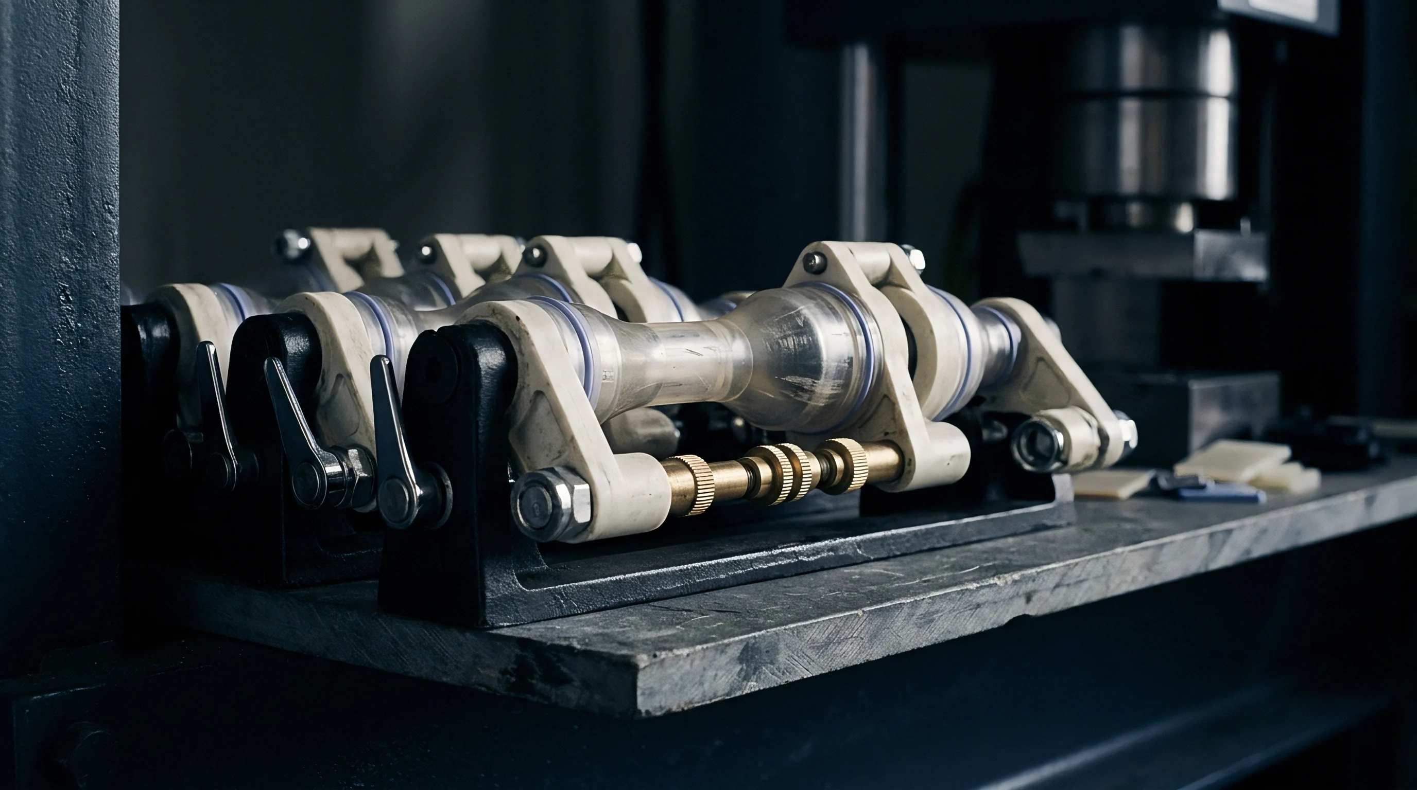

Zone
Injection molding of 30 percent glass fiber reinforced polyamide 66 creates a distinct three-layer structural morphology across part wall thickness. High velocity melt flow produces rapid shear forces near cavity walls, aligning glass fibers parallel to the filling trajectory within outer shell layers. The central core experiences predominant transverse shear flow, forcing fibers into perpendicular orientations relative to the primary flow vector.
Core fibers align transversely.
This microstructural variation creates localized anisotropy in thermal expansion behavior. Glass fibers carry a coefficient of thermal expansion near 0.5 multiplied by 10 to the minus sixth power per Kelvin, whereas the unreinforced polyamide matrix exhibits thermal expansion exceeding 80 multiplied by 10 to the minus sixth power per Kelvin. Shell layers expand minimally along the flow orientation, while the core layer undergoes substantial lateral displacement under identical temperature differentials.
Thermo-mechanical strain concentration builds at the narrow interface separating core and shell regions during rapid temperature changes.
Peak thermal strain concentration factor reaches 2.8 at the core-shell interface of 30 percent glass fiber reinforced polyamide 66 under temperature swings from minus 40 to 150 degrees Celsius.
When the component encounters cyclic thermal shocks, differential strain forces the matrix surrounding fiber tips into a viscoplastic response. Viscoplastic deformation accumulates irreversibly during high-temperature dwell periods. Local plastic strains accumulate.
The mechanical constraint imposed by adjacent, stiff shell layers prevents uniform expansion of the core matrix, escalating shear stresses along the inter-layer boundary.
Micro-cracking initiates at these structural boundaries long before gross component deflection becomes visible. Fiber-matrix debonding begins at fiber ends situated within the core-shell transition zone, driven by stress triaxiality during thermal cooling phases. Standard isotropic or linear elastic fatigue calculations miss this localized damage evolution entirely, leading to non-conservative life predictions in automotive under-hood enclosures and power electronics housings.
- Core-shell boundary mismatch generates persistent shear stresses due to stark differences in directional thermal expansion coefficients between adjacent structural layers.
- Fiber end stress concentration amplifies local matrix strain by factors exceeding two point five relative to far-field nominal strain values.
- Transverse thermal gradients across thick wall sections increase internal thermal stress peaks during rapid transient heating phases.
- Viscoplastic matrix relaxation transfers structural load from matrix to fiber tips during elevated temperature hold periods, accelerating local damage.
Designing component geometry without accounting for process-induced fiber orientation gradients results in localized microstructural cracking within five hundred thermal cycles, causing premature loss of sealing force and dielectric failure across high-voltage enclosures.
Kinetics
Viscoplastic deformation in semi-crystalline thermoplastics displays heavy dependence on temperature, strain rate, and stress state. Polyamides and polyphenylene sulfide exhibit non-linear creep-fatigue interaction under cyclic thermal loading, where time-dependent viscoplastic flow governs local strain accumulation around embedded glass fibers. Matrix yielding dominates.
The yield surface contracts during elevated temperature exposure and expands during thermal cooling, establishing a dynamic cyclic plasticity loop.
Constitutive modeling of this dynamic behavior requires continuous tracking of isotropic and kinematic hardening variables. Kinematic hardening captures the Bauschinger effect during reversed thermal strain paths, while isotropic hardening models matrix softening driven by thermal degradation and cyclic micro-damage accumulation. Norton-Bailey power laws describe secondary creep strain rates during high-temperature hold times, but explicit Chaboche-type viscoplastic formulations prove necessary to capture rate-dependent yield stress recovery across temperature bounds from minus 40 to 180 degrees Celsius.
| Polymer Matrix Grade | Glass Content Percentage | Yield Stress at 23C MPa | Yield Stress at 150C MPa | Creep Exponent n | Activation Energy kJ per mol |
|---|---|---|---|---|---|
| Polyamide 66 Dry | 30 | 175.0 | 62.0 | 4.2 | 142.5 |
| Polyamide 66 Conditioned | 30 | 110.0 | 38.0 | 3.1 | 118.0 |
| Polyphenylene Sulfide | 40 | 195.0 | 88.0 | 5.6 | 185.0 |
| Polybutylene Terephthalate | 30 | 140.0 | 45.0 | 3.8 | 130.0 |
Thermal strain amplitude directly modulates the rate of viscoplastic dissipation. During cooling from 150 to minus 40 degrees Celsius, high elastic stresses build due to thermal contraction constraint. As temperature stabilizes at the cold plateau, stress relaxation occurs slowly due to low atomic mobility within the amorphous polymer chains.
Conversely, heating to 150 degrees Celsius lowers matrix yield strength rapidly, converting elastic stress accumulated during constraint into permanent viscoplastic strain within seconds.
Viscoplastic relaxation during thermal dwell periods converts peak elastic stress into permanent plastic strain surrounding fiber tips.
Repeated thermal cycling generates a ratcheting mechanism in localized regions of non-zero mean stress. Each thermal cycle adds an increment of irreversible plastic shear strain at the fiber-matrix interface. Accumulation of this plastic strain destroys silane coupling agent bonds, initiating microstructural voids long before macro-scale yield occurs across the component bulk section.
- Thermal strain amplitude range establishes the envelope of cyclic plastic work input per thermal excursion cycle.
- High temperature hold duration governs the completeness of stress relaxation and total accumulated creep strain increment.
- Cooling rate severity determines peak elastic stress magnitudes generated prior to viscoplastic relaxation initiation.
- Moisture absorption level depresses glass transition temperature, lowering yield thresholds and accelerating room-temperature viscoplastic flow in polyamides.
Viscoplastic strain accumulation accelerates non-linearly once maximum cyclic stress exceeds fifty percent of matrix thermal yield strength at peak temperature.

Cavitation
Microstructural fracture initiation in short fiber reinforced plastics begins with void nucleation at localized regions of elevated stress triaxiality. Stress triaxiality, defined as the ratio of hydrostatic pressure to equivalent von Mises stress, reaches peak values at hemispherical fiber tips oriented normal to the loading axis. High hydrostatic tension pulls the matrix away from the glass fiber end, loading the sizing interface in direct tension.
Void nucleation begins.

Where Does Micro-Crack Nucleation First Accelerate?
Nucleation accelerates at acute fiber ends positioned inside transverse core layers where local matrix flow is constrained by surrounding orthogonal fibers. Hydrostatic tension prevents plastic shear yield from relaxing stress, forcing energy dissipation into chemical bond cleavage across the organosilane interface. Interface adhesion drops.
Thermal shock conditions worsen this mechanism through differential volumetric contraction rates between the glass fiber cylinder and the surrounding polymer cavity.
Fiber end debonding precedes matrix yield whenever local triaxial stress exceeds the interfacial shear strength.
Once interfacial debonding occurs at a fiber tip, the micro-void acts as a structural stress concentration site. Matrix material immediately adjacent to the debonded fiber tip experiences concentrated shear strain under subsequent thermal cycles. Viscoplastic flow drives the void to grow along the fiber perimeter, expanding transversely into the inter-fiber matrix spacing.
Inter-fiber micro-cracks coalesce when void length matches average fiber diameter, establishing a coherent micro-fracture front.
- Cut polished microstructural sections from thermal shock tested components using diamond blade wafering saws.
- Mount specimens in cold-curing epoxy resin under vacuum impregnation to preserve internal micro-crack morphology.
- Polish section surfaces progressively down to 0.05 micron colloidal silica suspension.
- Sputter coat polished sections with a three-nanometer gold-palladium layer to facilitate high-resolution scanning electron microscopy.
- Execute backscattered electron imaging at ten kilovolts to map micro-void frequency per unit cross-sectional area across shell and core zones.
Tooling vendors often claim that thermal fatigue cracking stems exclusively from improper molding barrel temperatures or wet resin processing. Micro-mechanical failure analysis demonstrates that perfectly dried, correctly molded resin still undergoes fiber end debonding under cyclic thermal strain if gate placement produces transverse fiber orientation across high thermal constraint zones.

Caliber
Accurate prediction of microstructural fracture initiation demands multi-scale modeling frameworks that bridge microscopic fiber geometry with macroscopic thermal stress fields. Homogenization methods represent the primary engineering approach for computing effective anisotropic thermo-elastic and viscoplastic material tensors. Mean-field homogenization schemes, including Mori-Tanaka and self-consistent formulations, compute average stress and strain fields in matrix and fiber phases based on second-order orientation tensors obtained from injection molding process simulations.
Mori-Tanaka models offer computational efficiency for full component structural analysis. These models approximate local field averages but underpredict peak stress concentrations occurring at closely spaced fiber ends. Full 3D Finite Element Representative Volume Element analysis models explicit fiber geometries, fiber end radius curvatures, and interfacial sizing layers directly.
FE-RVE calculations extract real spatial stress gradients at the expense of high computational load.
Consider a representative volume element of polyamide 66 containing 30 percent short glass fibers by weight, subjected to thermal cycling between minus 40 and 150 degrees Celsius. Assume average fiber aspect ratio of 25, mean fiber length of 230 microns, and an orientation tensor component along the primary axis of 0.65 in the shell and 0.15 in the core. The temperature differential of 190 Kelvin creates an unconstrained thermal strain differential of 1.48 percent between matrix and glass.
Mean-field homogenization predicts a peak hydrostatic stress of 42 MPa at the fiber end inside the core zone. FE-RVE analysis incorporating non-linear viscoplasticity reveals localized hydrostatic stress spikes reaching 88 MPa at fiber tips separated by less than five fiber diameters. Comparing these values against a critical interfacial debonding strength of 55 MPa demonstrates that mean-field calculations erroneously predict infinite life, while FE-RVE modeling correctly identifies micro-fracture initiation within 350 cycles.
| Modeling Architecture | Input Orientation Representation | Viscoplastic Capability | Computation Time per Cycle | Hydrostatic Stress Accuracy Percentage |
|---|---|---|---|---|
| Isotropic Equivalent Strain | None Scalar Density | Empirical Macro Law | Under 1 Second | Minus 62 |
| Mori-Tanaka Mean-Field | Second Order Tensor | Linearized Tangent Modulus | 5 to 12 Seconds | Minus 28 |
| Mori-Tanaka Benveniste | Fourth Order Tensor | Secant Modulus Approximation | 15 to 40 Seconds | Minus 18 |
| Full 3D FE-RVE Explicit | Actual Micro-CT Mesh | Fully Coupled Viscoplasticity | 4 to 18 Hours | Plus Minus 4 |
A comprehensive qualification dossier for thermally cyclically strained short fiber polymer parts combines microstructural orientation data, micro-mechanical modeling, and accelerated validation testing.
- Injection simulation orientation export mapping second-order orientation tensors directly onto structural finite element meshes via mapped spatial interpolation.
- Temperature-dependent viscoplastic properties measured across target thermal service range including high-strain-rate tension and multi-temperature creep relaxation data.
- Interfacial debonding stress threshold established via single-fiber pull-out or micro-bond testing under temperature-controlled environments.
- Micro-computed tomography validation scans confirming predicted fiber orientation distribution and baseline void content before thermal cycling exposure.
What structural parameter determines whether a coalescing micro-void converts into a self-similar propagating macro-crack or arrests at the nearest orthogonal fiber boundary?

Settlement
Controlling microstructural fracture initiation in production components requires translating multi-scale damage predictions into tooling design decisions and processing parameters. Gate location directly governs fiber orientation distributions inside the mold cavity. Gating location dictates survival.
Placing gates where melt fills critical structural mounting bosses via parallel flow paths prevents transverse fiber orientation in regions subjected to thermal constraint.
Tool cooling circuit layouts dictate local freeze-off rates during injection, altering shell-core thickness ratios. Rapid mold cooling thickens high-shear shell layers, increasing the volume of parallel-aligned fibers near the surface while compressing the core zone thickness. Slower mold cooling allows stress relaxation during cavity packing, narrowing shell thickness and broadening the core zone.
Adjusting mold temperature from 80 to 120 degrees Celsius in polyphenylene sulfide processing increases core layer thickness by 18 percent, shifting peak thermo-mechanical strain locations deeper into the wall section.
Compliance with ISO 20753 specimen preparation standards prevents flow-induced orientation skew during thermal cycling qualification.
Cavity pressure profiles must remain stable across long production runs to maintain uniform fiber packing density and minimize baseline void counts. Inadequate packing pressure leaves microscopic micro-voids around fiber clusters during volumetric shrinkage, effectively short-circuiting the initiation phase of thermal fatigue. Scientific molding protocols establish narrow process windows for hold pressure and time, ensuring gate seal occurs only after core consolidation completes.
Standard quality agreements must incorporate explicit clauses governing mold transfer approval, defining strict limits on allowable fiber orientation variance between original tool sign-off samples and full-scale manufacturing lots run on alternate injection presses.