Predicting Long Term Creep Deformation in Variable Wall Thickness Structural Components under Thermal Load
Non-uniform walls accelerate localized thermal creep by shedding stress into hot, relaxing cores; design requires coring out thick sections and rheological FEA sign-off before cutting steel.
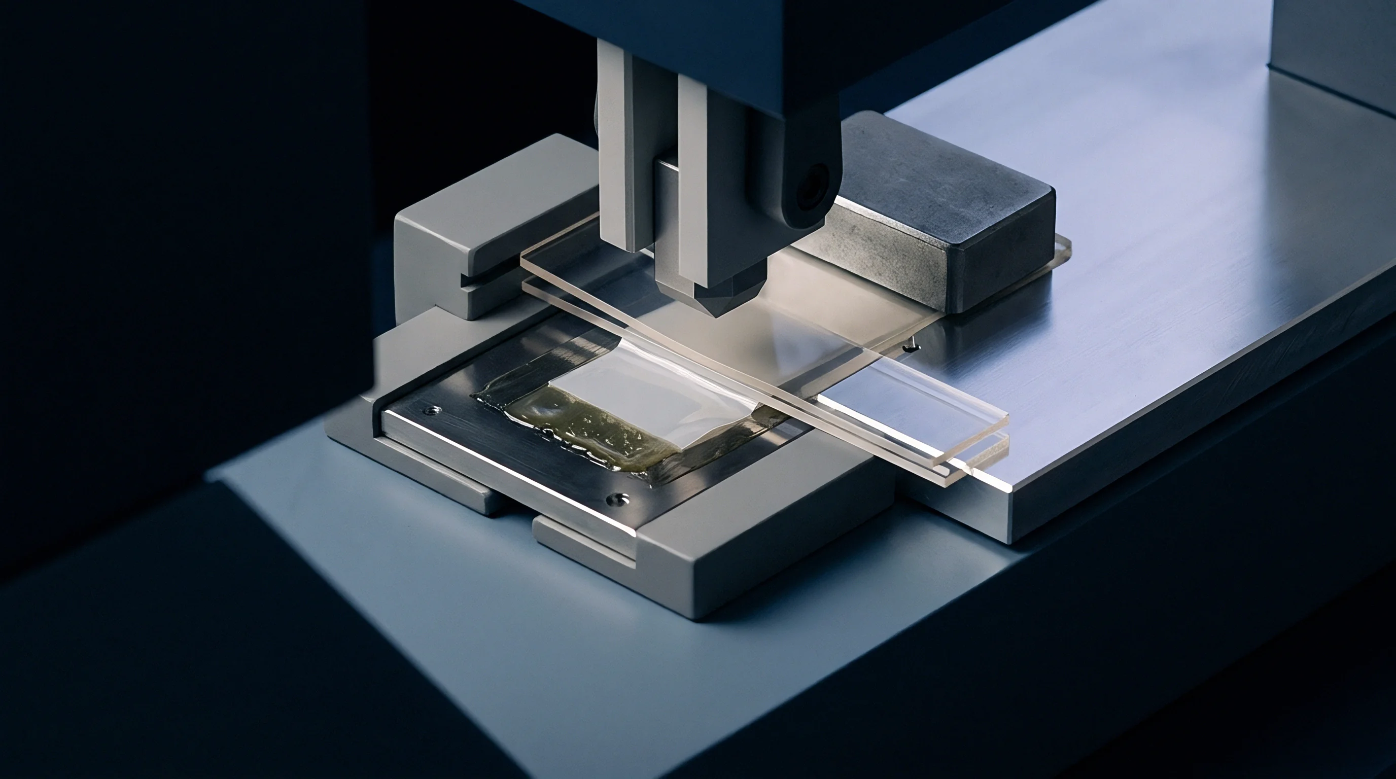

Gradient
An eight-millimeter structural rib transitioning into a three-millimeter shell sets up uneven heat dissipation that destabilizes an injection-molded housing. When operating environments subject the component to continuous temperatures above 100 degrees Celsius under a constant 22 MPa flexural load, creep deformation will not accumulate uniformly across the part. Local thickness variations alter both the internal temperature field and the stress profile through the wall over time.
Designing structural plastic components for long-term thermal service requires accounting for heat movement through shifting wall geometry and the rate at which viscoelastic polymers relax across adjacent features.
Across a uniform wall, heat flux moves symmetrically toward opposing cavity faces, establishing a predictable, steady thermal gradient through the thickness. Varying that thickness disrupts thermal equilibrium: heat travels laterally from thick bosses and heavy ribs into adjacent thin skins, pushing transition-zone temperatures well above nominal ambient levels. Because the viscoelastic modulus of semi-crystalline and amorphous thermoplastics drops sharply near the glass transition region, the warmer, thicker core loses creep compliance far faster than the cooler outer shell.
Viscoelastic Stress Shedding Mechanics
When a sustained bending moment works across a housing, structural stiffness depends on the instantaneous modulus of each sub-layer through the wall. Initial elastic loading sets up a linear stress profile across homogenous material, peaking at the outer fibers, but constant thermal exposure breaks down that baseline immediately. Running hotter than the surface, the interior of a thick wall undergoes accelerated primary viscoelastic relaxation, shedding mechanical load-carrying capacity as the core yields.
That localized relaxation forces internal stresses to redistribute, shunting load outward into the colder, stiffer exterior skins. Over extended operating hours, outer skin stress climbs until it exceeds the long-term strain limit of the polymer matrix. What reads on a drawing as an acceptable average stress across an 8 mm wall turns into localized tertiary creep rupture in a 2 mm skin layer that took on the transferred load.
Tensile creep modulus of 50 percent glass-filled polyphthalamide drops by 64 percent after 1,000 hours at 120 degrees Celsius under a constant 35 MPa bending stress.
Differential thermal expansion compounds this stress shedding. Thermoplastics expand five to fifteen times more than tool steel, so at operating temperatures, a thick section expands far more in absolute volume than the thin wall flanking it. That uneven volumetric expansion generates self-equilibrating internal stresses: compression builds inside the constrained thick core while tension develops in the surrounding thin walls.
Paired with external mechanical loads, these localized thermal stresses accelerate shear banding and molecular chain slippage within the matrix.
| Polymer Matrix | Filler Fraction | Glass Transition (Tg) (°C) | Continuous Service Temp (°C) | Instantaneous Tensile Modulus (GPa) | 1,000-Hour Apparent Modulus at 100°C (GPa) |
|---|---|---|---|---|---|
| Polyphthalamide (PPA) | 50% Short Glass | 125 | 140 | 17.5 | 8.2 |
| Polyamide 66 (PA66) | 30% Short Glass | 65 | 105 | 9.8 | 3.1 |
| Polyetheretherketone (PEEK) | 30% Short Glass | 143 | 240 | 13.0 | 10.4 |
| Polyphenylene Sulfide (PPS) | 40% Short Glass | 90 | 180 | 14.5 | 9.0 |
The damage from non-uniform creep rarely stops at bulk dimensional change. Variable wall geometry generates strain concentrations at radius transitions, where geometric notch effects intersect steep thermal gradients. An unfilleted transition between a 6 mm mounting boss and a 2.5 mm wall pushes the flexural stress concentration factor past 2.3.
At elevated temperatures, that localized intensity speeds creep propagation, starting micro-cracks long before the bulk part nears its predicted strain limit. The moulder absorbed an eighteen thousand dollar re-tooling cost when a thick structural bracket warped past its 0.4 millimeter geometry envelope after four months of thermal cycling.
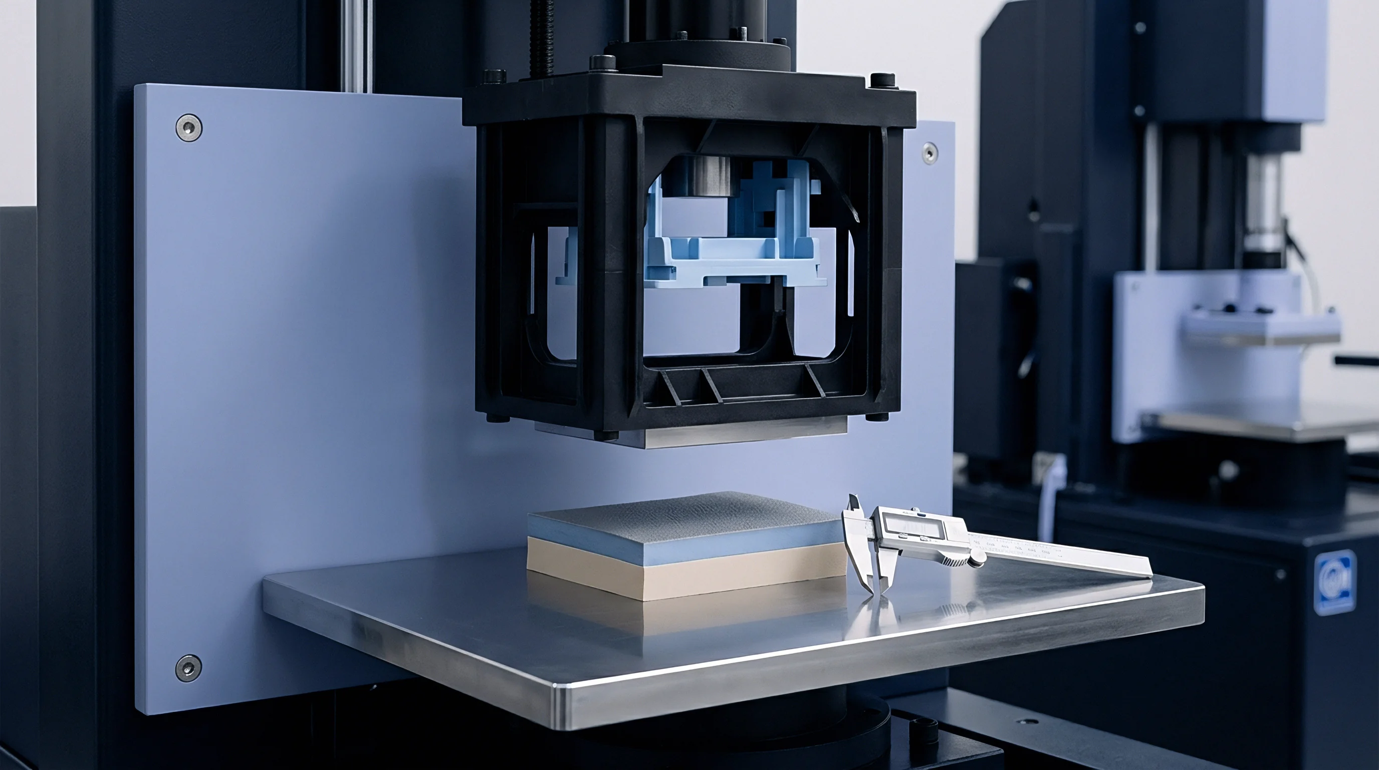
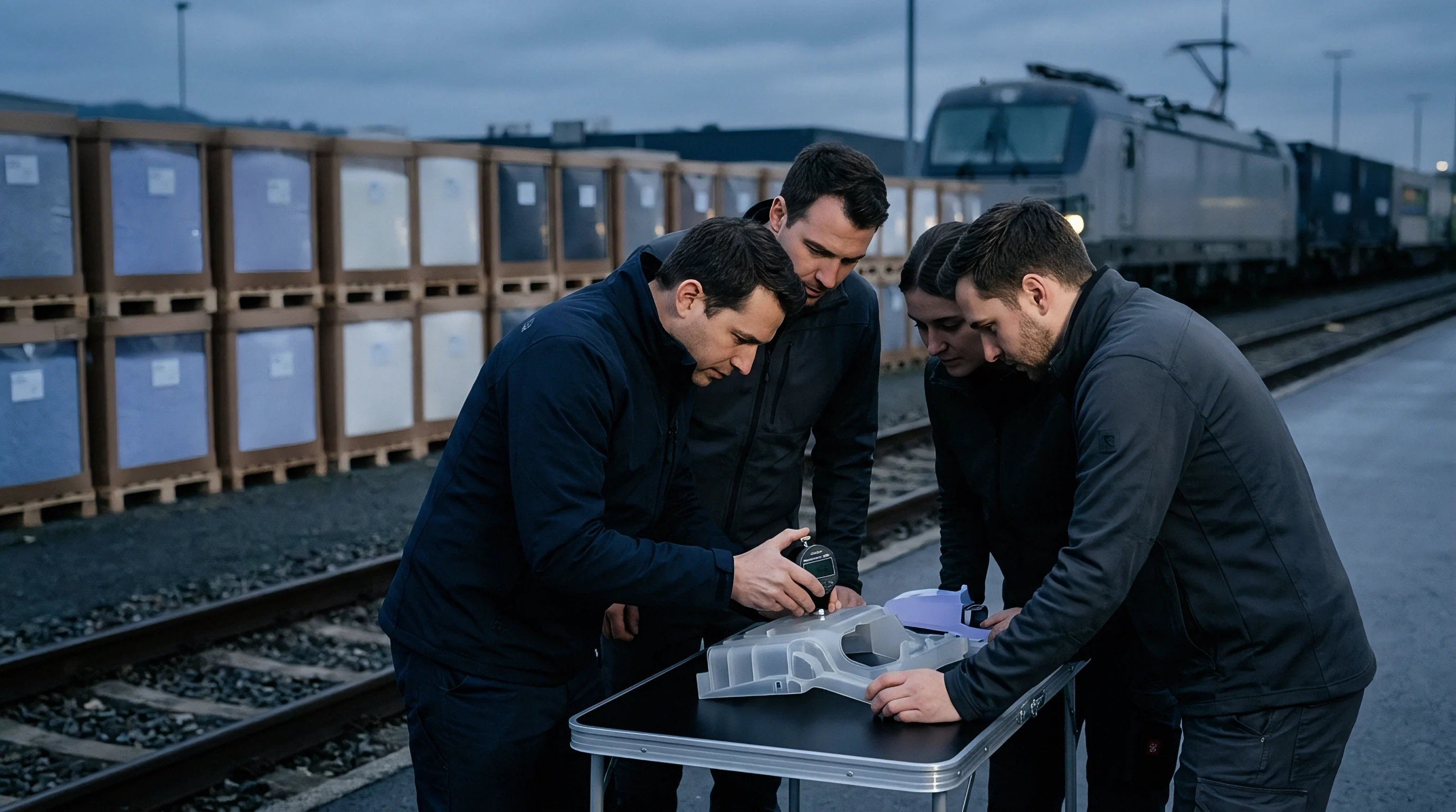
Superposition
Extrapolating short-term laboratory creep data to predict ten-year structural performance across variable thickness parts relies on time-temperature superposition. Standard tensile creep tests per ISO 899-1 generate data over hours or weeks, whereas components in automotive under-hood and industrial installations must hold geometry for 10,000 to 50,000 hours under continuous heat. Master curves constructed by shifting short-term compliance curves along a logarithmic time axis provide the mathematical bridge for those long-term predictions.
For amorphous polymers operating near their glass transition temperature, the Williams-Landel-Ferry (WLF) equation determines the horizontal shift factor aT as a function of temperature T relative to a reference temperature Tref:
log10 aT = frac-C1 (T – Tref)C2 + (T – Tref)
The empirical constants C1 and C2 reflect the free volume fraction and thermal expansion coefficient of the polymer structure. For semi-crystalline thermoplastics like PA66, PPA, and PPS operating below their melting points, an Arrhenius relationship models the temperature dependency of molecular relaxation times far more accurately:
ln aT = fracΔ HR left( frac1T – frac1Tref right)
Here Δ H represents the activation energy for viscoelastic flow, R is the universal gas constant, and the absolute temperatures T and Tref govern molecular mobility. Applying a single shift factor across an entire component with variable walls invites major prediction errors. Because a thick core retains heat longer and ages at a different rate than thin outer skins, each wall thickness zone effectively follows its own distinct local master curve.

Constitutive Power Law Modeling
To capture non-linear creep deformation under variable stress levels, the Findley power-law model defines total time-dependent strain ε(t) under uniaxial stress σ and temperature T:
ε(t, σ, T) = ε0(σ, T) + m(σ, T) left( fractt0 right)n
The stress-dependent instantaneous strain ε0 combines elastic and plastic responses upon initial loading. The coefficient m represents stress-dependent creep amplitude, while exponent n governs how rapidly strain rate attenuates over time. In glass-filled structural polymers, exponent n remains largely independent of stress below micro-yielding thresholds (typically n ≈ 0.15 – 0.35), but climbs sharply once matrix micro-cracking or fiber debonding initiates.
When stress levels shift due to thermal stress shedding across uneven thickness profiles, Eyring rate process theory provides the framework for non-linear stress superposition. The Eyring model considers molecular chain segments jumping across potential energy barriers, activated by both thermal energy and applied mechanical shear stress τ:
dotεcreep = dotε0 expleft(-fracΔ QR Tright) sinhleft(fracτ V k Tright)
Where Δ Q is activation energy, V is the activation volume for chain movement, and k is Boltzmann’s constant. In a thick structural rib where mechanical stress shed from the core elevates outer skin stress, this hyperbolic sine relationship causes an exponential rise in local creep strain rate once shear stress crosses threshold limits.
- Mould short-term ISO 527 Type 1A tensile specimens from the target lot using standardized processing conditions matching production cooling rates.
- Perform isothermal tensile creep tests per ISO 899-1 at five temperature steps spanning minimum operating temperature to maximum peak thermal exposure, recording continuous strain for 1,000 hours per step.
- Construct isothermal creep compliance curves D(t) = ε(t) / σ0 across all test temperatures on logarithmic time scales.
- Select a baseline reference temperature Tref and horizontally translate isothermal compliance curves along the logarithmic time axis until a continuous reference master curve forms.
- Calculate empirical activation energies Δ H via Arrhenius regression of shift factors aT, validating that shift linearity holds across the entire operating thermal window.
ISO 899-1 tensile creep testing at multiple temperature steps determines shift factors but fails to capture three-dimensional residual stress states from injection molding.
Predicting long-term deflection without measuring temperature-dependent linear viscoelastic limits leads directly to miscalculation. If stress anywhere in a variable wall part exceeds the linear viscoelastic threshold ~ typically 0.2 to 0.5 percent strain, depending on the polymer matrix ~ superposition breaks down. The material shifts into non-linear creep, where compliance climbs with stress level.
Published short-term flexural modulus figures indicate sufficient margin for continuous 80 degree operation, yet they overlook thickness-driven thermal lag.


Slab
The thermal history imposed by the injection moulding press establishes the baseline microstructural state of every variable wall component. When molten polymer at 290 degrees Celsius fills a mould tool maintained at 90 degrees Celsius, heat transfers rapidly into the steel cavity walls. The rate of cooling dictates crystallization kinetics, volumetric shrinkage, and the magnitude of frozen-in residual stresses.
Fourier’s law of thermal conduction dictates that cooling time tc scales quadratically with wall thickness s:
Cooling Time tc propto fracs2π2 α lnleft( frac8π2 fracTmelt – TmoldTeject – Tmold right)
Where α represents the thermal diffusivity of the polymer melt. Increasing wall thickness from 2.5 mm to 6 mm lengthens local cooling time by a factor of 5.7. Because piece-price targets constrain cycle times, molders eject components as soon as thin skins gain sufficient structural rigidity.
As a result, the interior of a thick section remains above its glass transition temperature upon tool opening, cooling slowly to room temperature in free air without cavity packing pressure.

Residual Stress Generation Mechanics
Unequal cooling across varying thicknesses establishes sharp parabolic residual stress profiles through the wall. As outer layers contact cold tool steel, they freeze rapidly under high packing pressure, establishing an un-oriented, dense solid shell. The molten interior continues to cool and attempt volumetric contraction, but the rigid outer skins prevent the core from shrinking freely.
This thermal constraint builds high tensile residual stresses in the interior core, balanced by compressive residual stresses in the outer skins. In unreinforced semi-crystalline polymers, differential cooling also alters local crystallinity: rapidly quenched thin walls exhibit low crystallinity and small spherulites, whereas the slowly cooled thick core achieves high fractional crystallinity with large spherulitic structures. This creates a spatial gradient in density, initial yield strength, and inherent creep resistance across the component cross-section.
- Core Voiding Rupture occurs when interior tensile residual stresses exceed molten core strength during free-air cooling, pulling vacuum micro-voids that drastically reduce shear load transfer under long-term creep load.
- Skin Core Delamination initiates at high-shear transitions between rapidly frozen outer skins and slow-cooled cores when localized thermal expansion stresses unseat weakly bonded crystalline boundaries.
- Thermal Relaxation Buckling manifests months after moulding as elevated operational temperatures relieve compressive skin residual stresses unevenly, releasing stored strain energy that warps the component out of planarity.
- Asymmetric Snap Unlatching results from variable thickness retention arms losing dimensional pre-load over time as high locked-in moulding stresses combine with service thermal loads to accelerate stress relaxation.
Process technicians evaluate cavity pressure traces to confirm gate seal timing before measuring post-mold shrinkage. Gate freeze timing presents a major operational challenge in variable wall tooling: if the gate feeds into a thin section that subsequently feeds a thick rib, the thin gate freezes early while the thick core remains molten. Packing pressure cannot reach the thick core during its volumetric contraction phase.
The resulting under-packed core exhibits low density, internal stress voids, and elevated baseline creep rates under subsequent thermal service. A section change that starves a thick core during packing converts continuous load into early shear failure along the mid-plane.

Solver
Accurate long-term dimensional prediction requires translating non-isothermal material physics into three-dimensional numerical finite element analysis (FEA). Standard linear elastic structural simulations fail to capture time-dependent strain accumulation, stress shedding, and thermal relaxation in variable wall components. Engineers must execute fully coupled thermal-mechanical simulations using advanced non-linear viscoelastic material subroutines.
The numerical workflow begins with a transient thermal conduction analysis. The finite element solver maps external continuous and cyclic thermal loads across the three-dimensional solid mesh, generating localized nodal temperature histories T(x, y, z, t). Because thermal diffusivity in polymers is low (10-7 m2/s compared to 10-5 m2/s in steel), sudden ambient temperature fluctuations create steep internal thermal gradients across thick sections that persist for hours before reaching thermal equilibrium.

Which Constitutive Subroutine Captures Thermal Creep Relaxation across Thick Sections?
Integrating non-linear creep into implicit finite element packages such as ANSYS or Abaqus requires implementing specialized constitutive subroutines (ANSYS USERCREEP or Abaqus UMAT). The total strain tensor boldsymbolε at any integration point is decomposed into elastic, thermal, and creep components:
oldsymbolε = boldsymbolεelastic + boldsymbolεthermal + boldsymbolεcreep
The incremental creep strain tensor doldsymbolεcreep over time step dt follows a generalized Prandtl-Reuss flow rule, assuming creep strain rate is proportional to the deviatoric stress tensor boldsymbols:
dboldsymbolεcreep = frac32 fracbardotεcreepbarσ boldsymbols , dt
Where barσ is the von Mises equivalent stress and bardotεcreep is the scalar equivalent creep strain rate computed from the temperature-dependent Findley or Eyring formulations. In variable wall geometry, the algorithm must update the local material Jacobian matrix at each integration point during every thermal time step, continuously recalculating instantaneous modulus, thermal expansion coefficient, and creep rate based on the exact nodal temperature and current equivalent stress level.
| Feature Geometry | Local Cooling Rate (°C/s) | Volumetric Shrinkage (%) | Short Fiber Alignment Tensor (A11) | Baseline Residual Stress (MPa) | FEA Creep Rate Scaling Factor |
|---|---|---|---|---|---|
| 2.0 mm Outer Shell | 45.0 | 0.65 | 0.82 (High Flow Axis) | -18.5 (Compressive) | 0.72 |
| 4.0 mm Transition Radius | 18.2 | 1.15 | 0.54 (Random Planar) | +4.2 (Tensile) | 1.18 |
| 8.0 mm Structural Boss Core | 4.1 | 2.40 | 0.28 (Transverse/Isotropic) | +22.8 (Tensile) | 2.45 |
Fiber-reinforced structural thermoplastics add orthotropic complexity to solver implementation. Injection moulding flow simulations (Moldflow or Moldex3D) predict short glass fiber orientation tensors Aij across variable wall features. Thin skin layers experience high shear flow, aligning fibers parallel to the gate flow direction and yielding high axial stiffness with low creep compliance.
Thick core regions experience low shear rates, resulting in transverse or random fiber distributions with lower stiffness and higher matrix-dominated creep compliance.
Structural FEA solvers must import these fiber orientation tensors using homogenization schemes such as Tandon-Weng or Mori-Tanaka models. The solver assigns a locally orthotropic elasticity tensor boldsymbolC(Aij) and orthotropic creep strain rate tensors to every element in the mesh. Neglecting flow-induced fiber anisotropy results in severe under-prediction of flexural warp: elements along thin outer walls deform far less than unaligned elements within thick interior ribs, inducing thermal-mechanical twisting modes that simple isotropic models miss completely.
Mapping unreinforced polymer creep properties onto short-glass structural components under-predicts anisotropic flexural deformation near the gate.
Long-term solver stability depends heavily on time-stepping algorithms. Explicit integration steps that exceed the local relaxation time constant of a warm thick element cause stress oscillation and numerical instability. Implicit integration algorithms with adaptive sub-stepping must monitor incremental creep strain per step, limiting dbarεcreep to less than 15 percent of elastic strain to guarantee solution convergence.
Whether non-linear damage accumulation algorithms can reliably predict multi-axial creep rupture in thick glass-filled bosses subjected to simultaneous cyclic thermal expansion remains unproven.


Validation
Theoretical FEA predictions require physical verification using empirical bench testing of prototype mouldings under simulated continuous thermal loads. Relying purely on virtual simulation to sign off multi-cavity production tooling creates unacceptable commercial exposure. Physical validation bridges the gap between ideal constitutive mathematics and press-side processing reality.
Full-scale component testing utilizes environmental thermal chambers equipped with pneumatic or dead-weight mechanical loading fixtures. Technicians mount strain gauges on prototype components inside thermal chambers to capture localized viscoelastic relaxation. Elevated temperature strain gauge rosettes rated for plastic substrates must be applied using high-elongation, temperature-resistant epoxy adhesives.
Gauge self-heating presents a major measurement error source on low-thermal-conductivity polymers: bridge excitation voltage must stay below 1.5 Volts to prevent local thermal degradation beneath the gauge grid.

Advanced Strain Metrology and Tool Modification Protocols
Digital Image Correlation (DIC) provides non-contact, full-field three-dimensional strain mapping across complex variable wall profiles inside glass-windowed thermal chambers. Optical DIC systems track high-contrast speckle patterns applied to component surfaces, measuring localized strain gradients at radius transitions down to 50 micro-strain accuracy. DIC reveals non-uniform thermal expansion, localized shear band formation, and stress-shedding displacement fields that single-point strain gauges miss entirely.
When physical validation testing indicates excessive long-term creep deformation in thick features, toolmakers must execute targeted geometric modifications to re-establish structural stability before committing final production steel. Coring out thick structural bosses and heavy ribs represents the primary design defense against non-uniform creep. Replacing a solid 8 mm boss with a cored-out cylinder featuring 2.5 mm uniform wall thickness and supporting gusset ribs eliminates thermal isolation, equalizes cooling rates, and reduces residual molding stresses by over 60 percent.
- Audit Wall Thickness Uniformity across all tool drawings, flagging any structural section change where local nominal wall thickness increases by more than 25 percent without functional coring.
- Verify Rheological Tooling Modifications by confirming gate sizes and locations maintain symmetric cavity fill paths and prevent early thin-section gate freeze-off before thick cores reach packing pressure.
- Conduct Thermal Imaging Metrology on first-shot T1 prototypes using calibrated infrared cameras to locate post-ejection thermal hot spots exceeding ambient core target temperatures by more than 15 degrees Celsius.
- Execute Accelerated Thermal Bench Creep Qualification by subjecting fully instrumented production-line components to 120 percent maximum operating thermal and mechanical loads for 500 hours, verifying total dimensional drift stays within absolute assembly limits.
Copper alloy inserts installed within steel tool cavities offer another powerful heat-management mechanism. High thermal conductivity materials such as Beryllium Copper (CuBe) or Ampcoloy (thermal conductivity 100 – 240 W/m·K compared to tool steel’s 25 – 30 W/m·K) drawn through core pins accelerate heat extraction from thick bosses. Equalizing tool surface temperatures across variable wall features eliminates localized thermal hot spots, suppressing spatial variation in physical aging and master-curve shift factors.
Paragraph 4.2 of the supplier quality agreement assigns full financial liability for post-mold thermal correction tooling to the party approving the wall thickness drawing without prior rheological FEA sign-off.


Warranty
Dimensional stability over multi-year operational lifespans carries direct commercial consequences for tooling investment, part landed cost, and product warranty liabilities. Sourcing teams purchasing variable wall structural components must reconcile long-term material creep physics with international moulding tolerance standards.
Standard engineering drawings reference DIN 16742 or ISO 20457 for plastic moulding tolerances. These standards define achievable manufacturing variations (Tolerance Groups TG1 through TG8) based on part dimensions, mould complexity, material shrink consistency, and processing capability. However, DIN 16742 explicit tolerance bands apply strictly to dimensions measured 24 hours post-moulding under standard laboratory conditions (23 degrees Celsius and 50 percent relative humidity).

Commercial Impact of Creep on Tolerance Budgets
Operating thermal loads and continuous mechanical stress consume tolerance budgets over time. A glass-filled structural bracket moulded to DIN 16742 TG4 tolerance of ± 0.18 mm on a 100 mm mounting center may meet initial quality control checks press side. But if elevated service temperatures induce a 0.5 percent long-term creep strain over 5,000 operating hours, the true physical dimension shifts by 0.50 mm.
This dimensional drift exceeds the total drawing tolerance band by nearly 300 percent, causing mechanical binding, gasket unseating, or structural assembly interference in the field.
| Nominal Dimension (mm) | DIN 16742 TG4 Initial Moulding Tolerance (mm) | 10,000-Hour Creep Strain at 80°C (15 MPa Load) (%) | Calculated Operating Creep Drift (mm) | Total Operational Dimension Shift (mm) | Commercial Warranty Risk Category |
|---|---|---|---|---|---|
| 20.0 (Boss Center) | ± 0.09 | 0.35 | 0.07 | ± 0.16 | Low – Within Clearance Fit |
| 80.0 (Rib Span) | ± 0.16 | 0.48 | 0.38 | ± 0.54 | High – Fastener Shear Exposure |
| 150.0 (Housing Flange) | ± 0.24 | 0.62 | 0.93 | ± 1.17 | Critical – Seal Interface Leakage |
| 300.0 (Main Frame) | ± 0.40 | 0.70 | 2.10 | ± 2.50 | Catastrophic – Interlocking Jamming |
Procurement teams write thermal load envelopes directly into tooling purchase orders to establish commercial liability. Tooling amortisation calculations depend on initial cavity count, cycle time, scrap rate, and expected steel maintenance costs across the lifetime production run. Variable wall thickness parts designed without proper coring force press setters to extend cooling times significantly, adding three to ten seconds to every cycle.
In a four-cavity tool running two million units annually, a five-second cycle extension driven by a thick rib increases machine-hour press costs by tens of thousands of dollars over the tool’s amortization window.
Tolerances held on the CMM twenty-four hours after molding mean nothing if operating heat expands thick sections past their assembly envelope after six months.
Modifying hardened tool steel to correct thermal creep deformation discovered late during field testing carries an astronomical cost multiplier. Cutting steel to add core pins, modify radii, or add cooling channels requires tool disassembly, EDM electrode machining, press re-qualification, and full First Article Inspection (FAI) re-validation under DIN 16742. Procurement agreements must define clear ownership of thermal deformation risk, specifying whether compliance is measured against 24-hour post-mold metrology or against long-term accelerated thermal validation testing.
Establishing clear material performance benchmarks, thermo-mechanical FEA sign-offs, and tool modification allocation clauses prior to steel cutting protects tooling budgets and prevents warranty disputes across the operating life of variable wall structural components.