Predicting Local Thermal Softening and Adiabatic Shear Banding during High Velocity Preform Inflation
Predicting adiabatic shear banding during high-velocity preform inflation requires coupled thermomechanical models evaluating strain hardening against rate-dependent thermal dissipation.


Shell
In high-speed preform inflation, mechanical drive pressure rapidly drives multiaxial polymer displacement over twenty to eighty milliseconds. Strain rates in this stretch blow moulding phase range from one hundred to one thousand reciprocal seconds. At these speeds, intense plastic shearing occurs in the polymer core before thermal energy can conduct into adjacent material layers or the tool cavity.
How strain rate distributes across the expanding wall determines if the polymer deforms evenly or focuses strain into structural instabilities.
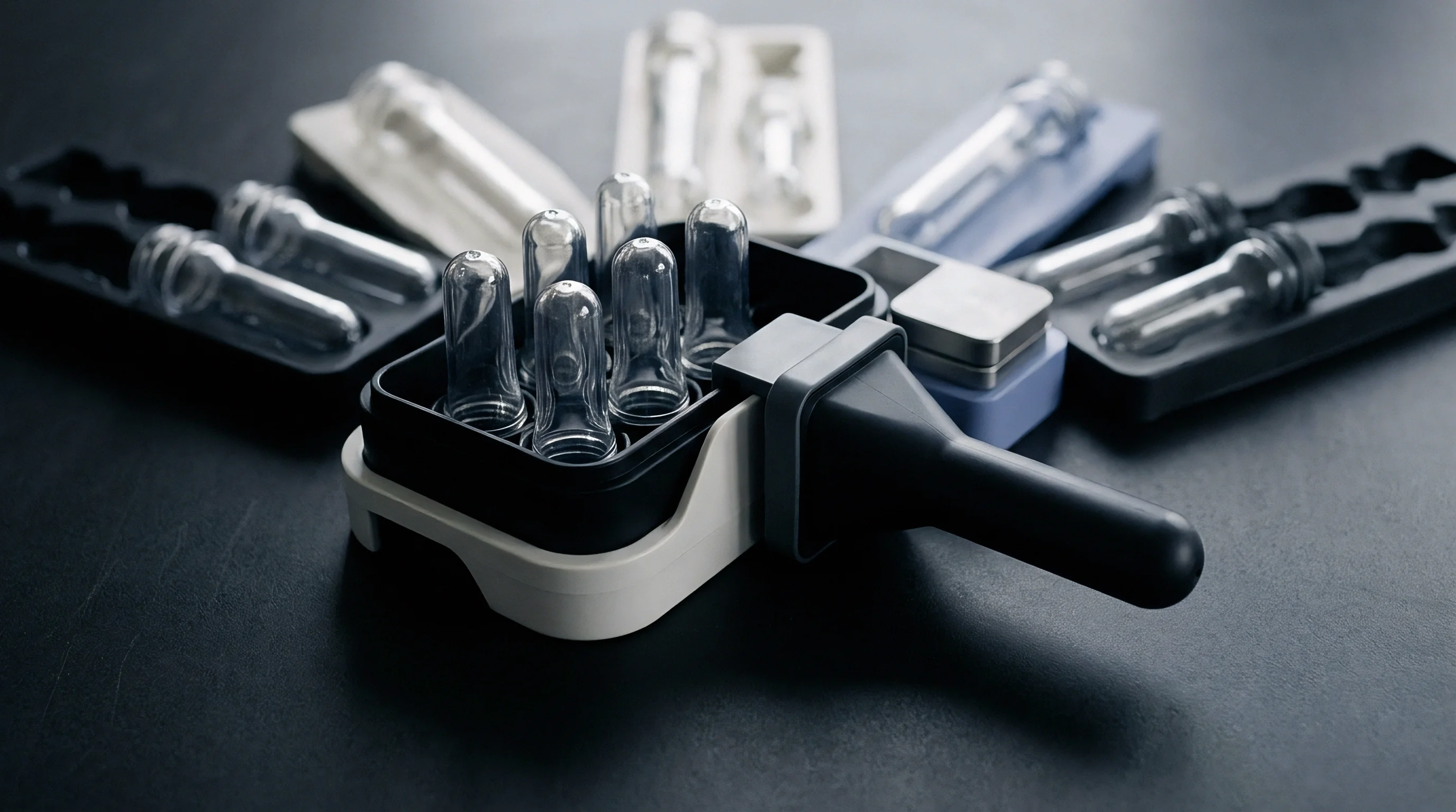
Initial strain distribution depends heavily on preform wall thickness. Standard stretch blow moulding uses injection-moulded preforms with walls between two and six millimetres thick. When high-pressure air enters the core, the wall stretches axially via the stretch rod while expanding circumferentially under internal air pressure.
The ratio of circumferential to axial strain defines the local stretch tensor. Thickness variations create matching stress variations: a section just fifty micrometres thinner than nominal experiences an immediate stress spike, driving up local strain rates and plastic flow.

Kinematics of Rapid Biaxial Expansion
Plastic flow accelerates quickly once expansion begins. Membrane stress equations describe how the expanding shell responds during rapid inflation: hoop stress increases with internal pressure and instantaneous inner radius, and decreases with instantaneous wall thickness. Axial stress depends on stretch rod force and applied pneumatic pressure.
During fast expansion, deformation outpaces the natural relaxation time of the polymer chains. Above its glass transition temperature, polyethylene terephthalate shows strong viscoelasticity, with effective yield stress depending heavily on strain rate.
Deformation accelerates when thermal energy from plastic work stays trapped in localized regions. Biaxial stretching forces polymer chains to uncoil and align along primary strain directions. At lower strain rates, this alignment causes strain hardening, which raises local resistance to stretching and spreads deformation into thicker adjacent material.
High strain rates generate significant internal friction. If heat builds faster than conduction can clear it, localized self-heating softens the material, undercutting the stabilizing effect of strain hardening.
| Inflation Phase | Internal Pressure (bar) | Stretch Velocity (m/s) | Local Strain Rate (s^-1) | Dominant Mechanical Regime |
|---|---|---|---|---|
| Pre-blow Initiation | 4.0 to 8.0 | 1.2 to 1.8 | 20 to 80 | Viscoelastic Linear Stretch |
| Main Blow Expansion | 25.0 to 40.0 | 2.0 to 2.5 | 250 to 850 | Non-Isothermal Plastic Shear |
| Wall Contact Touchdown | 35.0 to 40.0 | 0.0 | 1000 to 1200 | Adiabatic Contact Stabilization |

Deformation Velocities across Preform Wall Profiles
Temperatures across the preform wall are rarely uniform. Infrared systems deposit radiation unevenly through the thickness, creating a thermal gradient between the outer skin and the core. Ambient air cools the exterior surfaces while the inner core stays hot, giving the core a lower yield stress than the outer layers.
Once inflation starts, plastic deformation concentrates in this warmer core band, forming localized high-strain-rate shear zones.
Velocity measurements across the wall show steep gradients during the main blow sequence. Higher effective viscosity keeps initial deformation rates lower in the outer layers, while the inner core stretches at speeds above two metres per second. This speed difference creates internal shear stresses parallel to the wall surfaces.
When local shear crosses critical thresholds, slip bands form inside the core, concentrating plastic work into layers under one hundred micrometres thick.
Excessive preform temperature variance across the core wall accelerates strain concentration long before pressure stabilizes.
Optical metrology maps wall thickness variations across trial cavities to trace early deformation boundaries. Geometry variations interact directly with thermal gradients to dictate where shear bands initiate. Thinner regions carry higher membrane stresses, boosting local strain rates and causing rapid self-heating.
This creates a positive feedback loop: localized softening continuously lowers load capacity until cooler adjacent material arrests expansion. Controlling core temperature gradients prevents early shear localization before pressure peaks.
Achieving uniform stretch requires matching local wall temperatures to target strain rates across the whole preform. Designs with steep transition angles between the neck finish and body pose a heavy risk for shear band formation. These transition zones face complex multiaxial stress fields where hoop and axial components shift rapidly over short distances.
High-velocity air entering through the blow pin drives fast movement in these regions, creating local hot spots and shear bands. Smoothing wall transitions reduces these stress concentrations during inflation.
Core temperature plays a central role in wall distribution. Maintaining thermal balance across the thickness prevents central core layers from yielding prematurely. Preforms with uniform thermal profiles deform predictably across different inflation speeds, avoiding localized thinning during high-velocity processing cycles.

Rheology
Describing polymer behavior during stretch blow moulding requires models that capture non-linear strain hardening, strain rate sensitivity, and temperature-dependent thermal softening. Standard elastoplastic models fail to predict inflation because deformation happens between the glass transition and cold crystallization temperatures. In this window, polyethylene terephthalate and polypropylene show strong rate-dependent viscoplasticity alongside steep entropic strain hardening as molecules align.
Formulations such as the modified Buckley model or the G’Sell-Jonas equation express plastic stress as a function of strain, strain rate, and temperature. Flow stress reflects competing physical mechanisms during deformation: strain rate sensitivity indices measure how flow stress scales with velocity to stabilize against necking, while thermal softening terms drop flow stress exponentially as dissipation warms the material. Predicting adiabatic shear banding accurately depends on capturing this competition within numerical models.

Constitutive Modeling under Non-Isothermal High Strain Rates
Viscoplastic equations describe material response during rapid inflation. The G’Sell-Jonas model expresses equivalent stress by multiplying a structural strain factor, a strain rate exponent, and a thermal softening coefficient:
sigma(epsilon, dot_epsilon, T) = K exp(A epsilon^2) (dot_epsilon / dot_epsilon_0)^m exp(-C (T – T_0))
Parameter K sets the baseline strength, A is the strain hardening coefficient, m denotes strain rate sensitivity, and C defines thermal softening. Baseline temperature T_0 and reference strain rate dot_epsilon_0 act as normalization constants for calibration.
Strain rate sensitivity m helps distribute deformation across expanding zones. If a local spot stretches faster than adjacent material, the higher strain rate raises local flow stress, shifting deformation into neighboring regions. For PET at typical process temperatures, m ranges from 0.15 to 0.25.
Above three hundred reciprocal seconds, however, effective rate sensitivity drops, weakening the material’s ability to resist localized strain.
| Polymer Grade | Glass Transition Tg (K) | Hardening Factor A (-) | Rate Exponent m (-) | Softening Coeff C (K^-1) |
|---|---|---|---|---|
| Standard PET (IV 0.80) | 351 | 1.45 | 0.18 | 0.032 |
| High IV PET (IV 0.86) | 353 | 1.72 | 0.21 | 0.029 |
| Random Copolymer PP | 263 | 0.85 | 0.12 | 0.018 |
| Polyethylene Naphthalate | 393 | 2.10 | 0.24 | 0.041 |
Coupling Strain Hardening with Thermal Softening Functions
Strain hardening in semi-crystalline polymers comes from entropic elasticity in the uncoiling macromolecular network, followed by strain-induced crystallization. At a critical stretch ratio ~ typically between 3.0 and 3.5 for PET ~ chains reach full extension and flow stress climbs sharply. This sharp rise stabilizes wall thickness and prevents local rupture, setting the limit on how thin the wall can get before failing.
Thermal softening works directly against strain hardening. As mechanical work converts to heat, rising local temperatures weaken interchain interactions, lowering flow resistance. If thermal softening outpaces strain hardening, net flow stress drops even as strain increases.
This negative stress differential triggers adiabatic shear banding, concentrating deformation into narrow shear zones that cause localized wall thinning and optical haze.
Polyethylene terephthalate exhibits a strain hardening slope of 140 MPa at stretch ratios exceeding 3.2 when maintained at 102 degrees Celsius.
Evaluating constitutive predictions against high-speed camera footage of expanding preforms calibrates model coefficients. Standard tensile testing at low strain rates underestimates strain hardening slopes and misses adiabatic self-heating. High-velocity biaxial testing provides more realistic data, showing that rapid deformation shifts the start of strain hardening to higher stretch ratios while accelerating thermal softening.
Numerical models need continuous updates for temperature and microstructural changes. Assuming isothermal conditions creates massive errors in wall thickness predictions. When FEA solvers compute local mechanical work, they must immediately update temperature arrays and recalculate yield surfaces.
Without this real-time coupling, simulations overestimate wall uniformity and miss shear localization zones entirely.

Can Modified Buckley Models Capture Shear Localization?
The modified Buckley formulation splits polymer response into a bond-stretching network component and an entropic strain-hardening component. The bond-stretching term handles initial yield and strain rate sensitivity, while the strain-hardening term models orientation-induced molecular locking. This dual-network approach accurately captures non-linear stress-strain curves along variable temperature paths during preform inflation.
Capturing shear localization requires high-resolution spatial discretization in constitutive modules. The Buckley model incorporates glass transition dynamics by scaling relaxation times with Williams-Landel-Ferry or Arrhenius temperature functions. Under rapid adiabatic shear, local temperature spikes shorten relaxation times dramatically, making the viscoelastic matrix behave like a lower-viscosity fluid.
This drop in relaxation time accelerates localized strain accumulation inside micro-shear bands.
- Thermal softening breakdown occurs when heat generation shortens relaxation times faster than chain alignment can raise flow resistance.
- Strain hardening saturation arises at extreme stretch ratios where molecular chains reach extension limits, cutting off further alignment.
- Adiabatic yield drop manifests as an abrupt decrease in equivalent flow stress during high-velocity pressure application.
- Shear band propagation extends localized material thinning along maximum shear stress trajectories across the preform sidewall.
Treating stretch ratios as the sole determinant of preform design ignores inflation speed limits. That oversimplification overlooks how rate-dependent thermal softening can override nominal stretch limits during high-speed production. In practice, processing parameters must be tuned to specific strain rate windows to preserve structural integrity.

Dissipation
Plastic deformation converts mechanical work into heat through viscous dissipation and internal friction between sliding macromolecular chains. The fraction converted is defined by the Taylor-Quinney coefficient. While metals show predictable values around 0.90, polymers vary from 0.55 to 0.85 depending on strain rate, temperature, and total plastic strain.
Energy transformation during rapid inflation occurs far faster than heat can diffuse through the wall. Thermal diffusion time t_diff scales with the square of wall thickness divided by thermal diffusivity. For a four-millimetre PET wall with a thermal diffusivity of 1.2 x 10^-7 metres squared per second, diffusion takes roughly 13.3 seconds.
Because inflation completes in just 0.050 seconds, generated thermal energy stays entirely trapped inside the deforming zone.
Taylor-Quinney Coefficient and Plastic Work Conversion
Adiabatic conditions take over once inflation speeds cross critical thresholds. The local temperature rise delta_T during plastic deformation follows the thermodynamic relation:
delta_T = (beta / (rho Cp)) integral(sigma d_epsilon_p)
Density rho and specific heat capacity Cp define the matrix’s volumetric heat capacity. The Taylor-Quinney coefficient beta determines how much plastic work converts directly to heat, while the remainder is stored as entropic elastic energy and structural conformational changes.
Measuring beta for PET under high strain rates shows strong strain dependence. At lower strains before chains align, beta hovers near 0.60 because significant energy goes into uncoiling. Once stretch ratios pass 2.5 and orientation increases, internal friction rises, pushing beta toward 0.82.
This higher conversion rate accelerates self-heating right when the preform experiences peak deformation rates.

Thermal Diffusion Timescales versus Blow Cycle Speeds
Peclet number calculations confirm that rapid inflation is essentially adiabatic. The dimensionless Peclet number Pe compares deformation-driven heat transport to thermal conduction:
Pe = (v L) / alpha
With deformation velocity v, wall dimension L, and thermal diffusivity alpha, Peclet numbers exceed 5,000 during main blow expansion. Values above 100 mean heat conduction is negligible over the deformation timeframe, keeping temperature spikes isolated right where deformation occurs.
Compliance with ISO 294 mold temperature control protocols prevents outer wall skin chilling while preserving internal core heat balance.
Temperature spikes inside high-strain shear bands can exceed twenty-five Kelvin above initial preform temperature. In PET near 100 degrees Celsius, a twenty-five Kelvin rise cuts equivalent flow stress by over forty percent. That sudden drop destabilizes deformation: material in the hot shear zone stretches preferentially while cooler neighboring regions stop deforming, creating severe local thinning.
Oven settings determine core thermal flux. Heat trapped in central wall layers lowers the energy required to start plastic flow. Heat transfer models must account for this internal dissipation to accurately predict container wall profiles and prevent failure during pressure testing.
Which analytical measurement technique can resolve three-dimensional thermal dissipation fields inside a four-millimetre preform wall during a thirty-millisecond blow event without altering local boundary conditions?


Criterion
Predicting adiabatic shear banding during rapid preform inflation requires a criterion that evaluates when plastic flow turns unstable. Classical necking criteria built for isothermal tension, like the Considère condition, break down under rapid, non-isothermal biaxial deformation. A suitable instability criterion must handle strain hardening, strain rate sensitivity, and thermal softening occurring simultaneously under multiaxial stress.
Shear localization begins when thermal softening outpaces the stabilizing effects of strain hardening and strain rate sensitivity combined. Mathematically, instability sets in when the adiabatic tangent modulus turns negative. Evaluating this transition requires linear stability analysis, introducing small perturbations in wall thickness or temperature into the continuum equations to track whether they grow or decay over time.
Instability Thresholds for Adiabatic Shear Band Formation
The general instability parameter I_g for adiabatic shear localization under non-isothermal conditions is expressed through the partial derivatives of equivalent stress sigma with respect to plastic strain epsilon, strain rate dot_epsilon, and temperature T:
I_g = (1 / sigma) (d_sigma / d_epsilon) + (m / dot_epsilon) (d_dot_epsilon / d_t) – (C beta sigma) / (rho Cp)
Instability begins when I_g falls below zero. The first term is the stabilizing effect of strain hardening, the second reflects strain rate acceleration, and the third accounts for destabilizing thermal self-heating. At high strain rates, rapid heat accumulation makes the negative thermal term dominant, driving I_g negative and triggering shear bands.
Multiaxial stress alters instability thresholds compared to uniaxial tension. Stretch blow moulding creates a complex stress field governed by the ratio of hoop to axial stress. High hoop-to-axial ratios concentrate plastic shear along planes roughly forty-five degrees to the principal stress axes.
Adding stress triaxiality and Lode angle dependence to the instability criterion significantly improves failure predictions.
| Wall Thickness (mm) | Critical Strain Rate (s^-1) | Adiabatic Temp Rise (K) | Instability Index I_g | Observed Failure Mode |
|---|---|---|---|---|
| 2.5 | 450 | 14.2 | +0.04 | Uniform Biaxial Stretch |
| 3.5 | 320 | 19.8 | +0.01 | Minor Wall Off-Centering |
| 4.5 | 210 | 26.5 | -0.03 | Localized Shear Banding |
| 5.5 | 140 | 32.1 | -0.08 | Structural Micro-Rupture |

Perturbation Analysis of Wall Thinning Mechanics
Linear perturbation theory provides quantitative growth rates for micro-geometric irregularities in the preform wall. An initial wall thickness imperfection delta_h_0 amplifies over time according to an exponential growth law governed by the instability growth rate eta:
delta_h(t) = delta_h_0 exp(eta t)
The growth rate eta depends directly on the balance between thermal softening and strain hardening. Positive eta values mark rapid amplification of thickness variations, leading straight to localized shear bands and part failure.
Pressure rises in milliseconds. The pre-blow pressure ramp rate dP/dt determines whether perturbations grow or decay during early expansion. Ramping pressure too fast spikes the deformation rate before strain hardening can stabilize the wall.
Matching the pressure ramp to material relaxation dynamics suppresses perturbation growth, keeping wall profiles uniform.
- Preform thermal profiling identifies cross-sectional temperature variations using calibrated infrared pyrometry arrays.
- Inflation pressure curve optimization aligns pre-blow pressure ramps with stretch rod position profiles.
- Constitutive stability boundary mapping calculates local I_g values across finite elements in the preform mesh.
- Tooling air vent verification confirms high-pressure exhaust capability so back-pressure does not retard final touchdown.
Quality agreements based on DIN 16742 plastic moulding tolerances cover dimensional specs but omit high-speed deformation defects. Procurement teams should include explicit adiabatic shear band clauses in tooling sign-off contracts to ensure process windows are validated at full machine speed.
Cooling channels set the skin temperature, but managing the core temperature controls the instability boundary ~ keeping material deformation within a stable regime across the full inflation sequence.


Window
Defining the process window for high-speed stretch blow moulding requires tight control over preform heating profiles, stretch rod kinematics, and pneumatic timing. Operating outside this window triggers thermal softening defects or premature shear localization. A robust operating window prevents quality drift across multi-cavity tools running up to two thousand containers per cavity per hour.
Infrared reheat oven settings determine the core-to-skin thermal profile across the preform wall. Quartz lamps operating in the short-wave infrared spectrum penetrate the wall with depth-dependent absorption. Poor lamp power balance creates uneven profiles ~ overheating the outer skin while leaving the core cold, or under-heating central layers.
Core temperature control is fundamental to process stability.

Infrared Heating Profiles and Core Temperature Gradients
Radiation attenuation through the preform wall follows the Beer-Lambert law, modified for spectral emission bands of quartz heaters. The energy absorption rate Q(z) at depth z within the wall section is expressed as:
Q(z) = integral(I_0(lambda) kappa(lambda) exp(-kappa(lambda) z) d_lambda)
Incident spectral intensity I_0(lambda) and absorption coefficient kappa(lambda) govern radiant heat absorption through the wall thickness. Adjusting lamp power across oven zones modifies spectral balance, allowing precise tuning of core temperature profiles.
Oven ventilation speed controls outer skin cooling. Blowing ambient air across preform exteriors removes surface heat while internal radiation continues heating the core. This flattens thermal gradients across the outer layers, preventing skin overheating and ensuring consistent yield behavior when the stretch rod makes contact.
Preform wall temperature variations exceeding three degrees Kelvin across the circumference trigger wall off-centering within fifty milliseconds.
Tracking cavity pressure curves during T1 tool sign-off verifies pressure rise rates against numerical models. Balance across large mould frames relies on hot runner consistency and air manifold layout. Pressure variations between cavities alter local strain rates, pushing certain cavities into adiabatic shear banding while adjacent ones perform normally.
Stretch rod velocity must synchronize with the opening of the pre-blow air valve. Advancing the rod before pre-blow pressure starts applies purely axial tension, inducing necking near the gate. Delaying pre-blow air lets the rod puncture or over-stretch the base.
Proper timing establishes a balanced biaxial stress state from the moment expansion begins.

Finite Element Mesh Density Rules for Shear Localization
Simulating adiabatic shear banding requires fine spatial and temporal resolution in finite element solvers. Standard continuum meshes fail to capture localized shear bands because element interpolation functions smooth out steep temperature and strain gradients across narrow zones. Reliable defect prediction depends on strict mesh refinement through the wall thickness.
Element formulation choice dictates numerical accuracy. Three-dimensional solid elements with reduced integration and hourglass control prevent element locking under complex incompressible flow. Solid shells offer computational speed but need validated shear correction factors to model cross-wall dissipation accurately.
Solvers should use fully coupled thermomechanical integration algorithms with adaptive steps down to microsecond scales.
Because mesh density governs thermal resolution, at least ten elements through the wall thickness are needed to resolve core dissipation gradients. Coarser meshes over-predict heat diffusion across element boundaries, artificially suppressing temperature spikes and masking shear band initiation.
Incorrect pre-blow pressure ramp rates cause localized core overheating, producing wall thinning defects that degrade drop-impact resistance and lead to bottle collapse during high-speed filling.

Margin
The commercial viability of high-speed stretch blow moulding lines hinges on keeping scrap rates low. Adiabatic shear banding and localized thermal softening introduce subtle structural wall defects that cause containers to fail during filling, palletizing, or storage. Catching and eliminating these defects during tool design and process qualification protects margins and avoids costly field returns.
Scrap directly impacts landed cost. Operations running seventy-two thousand bottles per hour consume huge volumes of resin; a scrap increase of just half a percent adds hundreds of thousands of dollars in annual material waste and lost throughput. Thermal softening defects are particularly troublesome because micro-shear bands often pass vision inspection systems unnoticed, surfacing later as drop-test failures or stress cracks in distribution networks.

Commercial Impact of Shear Banding Scrap Rates
Container performance testing sets strict limits on wall thickness variation. ISO 16104 standards mandate rigorous drop-impact and top-load vertical crush testing. Shear bands act as stress concentrators within container walls, reducing drop-impact energy absorption by up to sixty percent compared to uniform containers.
Under impact, cracks initiate along localized shear planes, leading to total containment failure.
Cavitation choices influence both process stability and financial performance. Large multi-cavity tools require balanced hot runners and precise cooling layouts to maintain identical thermal conditions across all cavities. Cavity-to-cavity temperature differences as small as two degrees Celsius induce local strain rate variances during high-speed inflation, pushing peripheral cavities into shear localization regimes.
Investing in well-balanced cooling channels mitigates scrap risk across high-volume lines.

Tooling Cavitation Strategy and Preform Specification Rules
Preform geometry constrains stretch velocity. Designing preforms with optimized length-to-diameter ratios lowers necessary inflation speeds, keeping strain rates in stable regimes. Shorter, thicker preforms require higher stretch ratios and faster inflation, raising shear heating risks.
Longer, thinner preforms lower required stretch ratios and widen the process window, though they require larger injection molds and longer cycle times.
Calculating landed cost penalties when scrap exceeds two percent on high-speed lines demonstrates the financial value of thermal optimization. Upfront investment in preform core cooling design and high-resolution IR oven controls pays back quickly by expanding the safe process window and preventing shear band defects.
- Preform weight optimization balances raw material costs against the minimum wall thickness needed to prevent shear localization at high speeds.
- Cavitation scaling limits establish maximum cavity counts based on hot runner heat uniformity across large tool platens.
- Core pin cooling specifications define internal water flow rates needed to hold preform core temperature tolerances within target bands.
- Process window auditing tracks drift in pneumatic pressure delivery and IR lamp output over continuous multi-day production runs.
Because tooling balance dictates cavity fill, contracts that base part acceptance solely on room-temperature dimensional inspection allow flawed preform designs to pass sign-off. Procurement teams should include process-window validation clauses in tooling purchase orders, requiring multi-cavity runs at full production inflation speed before authorizing final payment.