Measuring Polymer Contact Conductance on Polished Tool Steel Surfaces
Polymer contact conductance collapses from 2500 to 150 W/(m²·K) upon cavity depressurization, doubling cooling resistance across polished tool steel interfaces.
Quench
Cavity steel at ninety degrees Celsius meets incoming polypropylene melt at two hundred and thirty degrees under eight hundred bar of specific injection pressure. Direct conduction dominates during the first eighty milliseconds. Molten resin wets the microscopic asperities of an SPI A2 polished finish, compressing trapped micro-pockets of air and driving interfacial conductance above two thousand five hundred watts per square meter-kelvin.
Heat flux spikes across the boundary. Solidification begins at the wall.
Shrinkage severs direct conduction. As the frozen skin develops tensile strength and bulk resin contracts through its specific volume transition, contact pressure against the cavity wall drops toward zero. The interface separates into discrete microscopic contact points separated by an insulating vapor film.
Measured conductance plummets from two thousand watts per square meter-kelvin to less than two hundred watts per square meter-kelvin within three seconds of gate seal. Coolant flow cannot bridge air.
A measured contact conductance drop from 2200 W/(m²·K) to 180 W/(m²·K) at depressurization delays core freezing by four point six seconds on a two-millimeter nominal wall.
Tooling quotes routinely price cycle time on the assumption of steady-state heat extraction through tool steel. Standard boundary conditions in flow simulation software apply a fixed thermal contact value across the entire cycle, typically twelve hundred or fifteen hundred watts per square meter-kelvin. This mathematical convenience misrepresents the physical interface.
The press operator chasing part dimensions on a warm tool increases hold time to compensate for sink marks, unaware that thermal resistance at the steel boundary has multiplied tenfold. Machine time accumulates unbilled.
Mould builders polishes cavity inserts to SPI A1 or A2 mirror specifications to guarantee optical clarity and clean ejection. Surface finish also establishes the real area of mechanical contact when polymer melt hits the tool wall. A high polish removes tool marks, narrowing the distribution of asperity heights.
Melt under pressure deforms against these flattened peaks, increasing the true contact area relative to the apparent geometric area. Semicrystalline resins crystallize against this boundary under severe thermal gradients, forming a dense skin layer with oriented morphology distinct from the core.
Premature depressurization breaks the thermal bridge before core enthalpy leaves the part. When packing pressure releases too early, volumetric contraction pulls the polymer skin inward, leaving a gap of five to twenty micrometers across wide planar surfaces. Heat accumulates in the part core, reheating the frozen skin from within and causing post-ejection warpage that rejects the batch during first-article dimensional inspection.

Cell
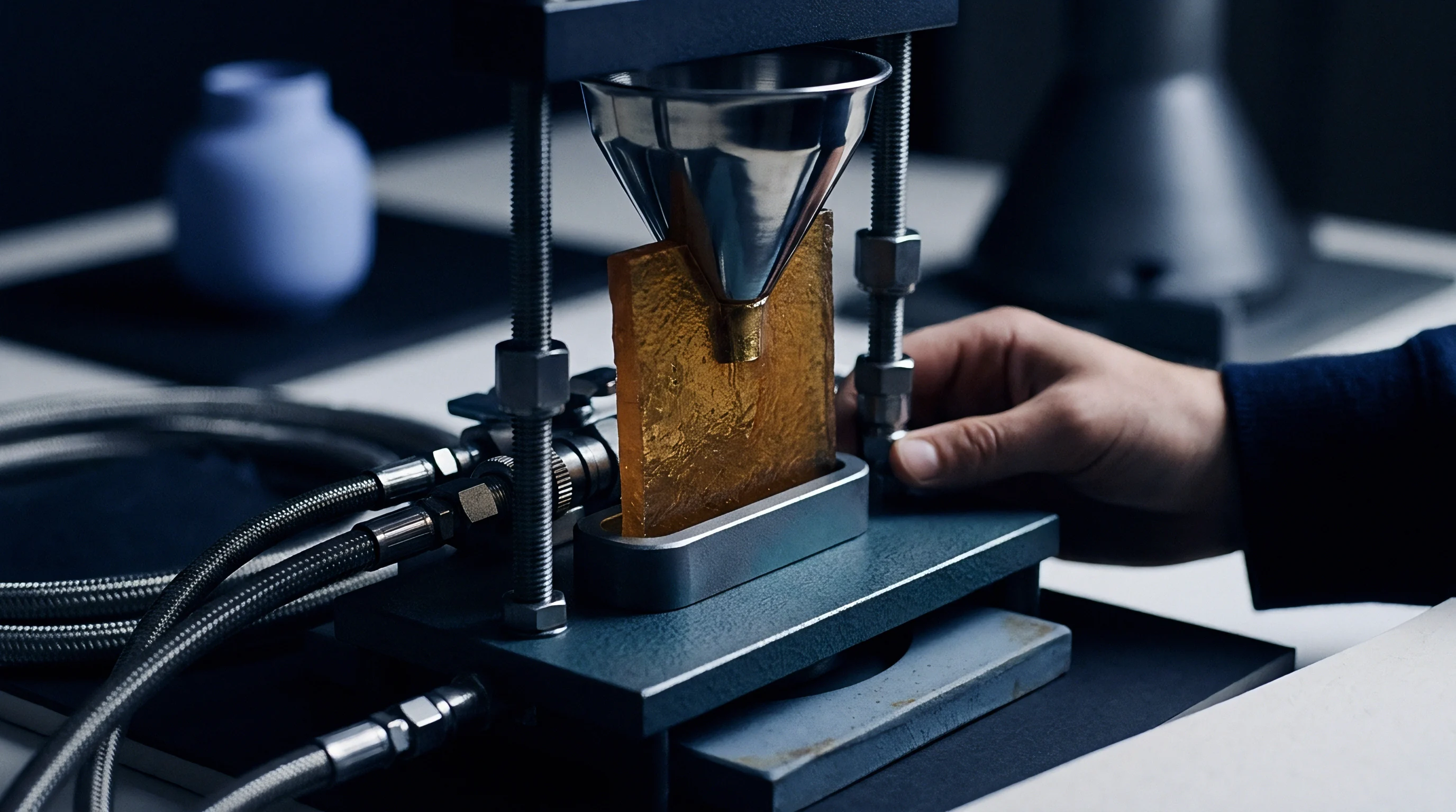
Bench measurement of interfacial conductance isolates thermal phenomena from the mechanical vibrations and hydraulic spikes of an operating injection press. Dedicated test apparatuses sandwich a polymer sample between two cylindrical tool steel calorimeters inside a vacuum chamber or controlled atmospheric enclosure. Pneumatic or hydraulic actuators apply static contact pressure ranging from five bar to one thousand bar, matching cavity packing conditions.
Cartridge heaters establish a known thermal gradient across the upper steel column, while a circulating chiller stabilizes the lower receiver. Subsurface thermocouple columns calculate axial heat flux through Fourier one-dimensional conduction equations.
Standard ASTM D5470 test configurations provide steady-state thermal impedance data for thin thermal interface materials, but injection tooling requires transient dynamic response. Polymer melts solidify continuously against colder steel, altering density, thermal conductivity, and modulus during the test window. Dynamic test cells incorporate rapid inductive heating coils or pneumatic injection chambers that push molten resin against a pre-tempered steel block within twenty milliseconds.
Piezoelectric load cells record actual normal force at the interface, eliminating error from mechanical friction in actuator guide bushings.
Under DIN EN ISO 22007-4, laser flash analysis captures bulk resin diffusivity while instrumented contact cells isolate the interfacial contact impedance.
Calorimeter design demands precise material selection. Tool steel alloys such as AISI H13 (DIN 1.2344) or AISI 420 (DIN 1.2083) represent actual production cavity inserts, but their moderate thermal conductivity (approximately twenty-four to twenty-nine watts per meter-kelvin) reduces the signal-to-noise ratio of temperature drops across short distances. High-conductivity copper alloys like beryllium-copper (C17200) produce clean temperature differentials, yet their asperity deformation under load differs fundamentally from hardened tool steel.
Production-representative testing requires using the specified tool steel grade, hardened to fifty-two HRC and polished using identical diamond compounds.
Guarded hot-plate arrangements prevent lateral heat dissipation. Radial thermal losses compromise one-dimensional flux assumptions, skewing calculated contact coefficients upward. Guard heaters matched electronically to the primary stack temperature maintain zero radial gradient across outer insulation sleeves.
The measurement sequence follows a strict operational order.
- Preheating cycle raises the donor steel block to the target melt processing temperature while circulating coolant brings the polished receiver block to production cavity setpoint.
- Specimen introduction seats the solid resin preform or injects molten polymer directly into the measurement chamber under atmospheric inert gas purge.
- Actuator engagement ramps interfacial pressure to the selected packing plateau within forty milliseconds to match injection velocity profiles.
- Data acquisition records high-speed thermocouple voltages at two kilohertz across the first five hundred milliseconds of thermal shock.
- Depressurization stage vents actuator pressure at a controlled linear rate to replicate gate freeze-off and subsequent volumetric shrink gap initiation.
Calibration requires reference tests using high-purity electrolytic copper blocks with known contact conductance profiles. Surface oxidation on tool steel inserts alters surface energy and emissivity, requiring rigorous mechanical repolishing and solvent ultrasonic cleaning between test runs. Grease films or silicone contamination shift measured resistance values by twenty to forty percent.
Test protocols governed by ISO 6721 for dynamic mechanical properties and ASTM E1225 for guarded-comparative-longitudinal heat flow govern measurement accuracy.
Tooling supply agreements referencing ASTM E1530 for thermal resistance testing bind the mouldmaker to verified heat transfer benchmarks, preventing disputable cycle-time guarantees from entering technical sign-off dossiers.

Topography
Profilometry scans of cavity surfaces uncover microscopic plateaus and valleys that dictate true physical contact. Even a mirror-polished cavity insert prepared with three-micrometer diamond compound retains surface roughness. Stylus profilometry and white light interferometry measure average roughness values between 0.012 and 0.050 micrometers for SPI A1 and A2 finishes.
When molten polymer hits these asperities, viscous resistance prevents the melt front from filling every valley instantly. Trapped gases form micro-voids that throttle interfacial heat transfer.
| Polymer Grade | Surface Finish | Ra (µm) | Contact Conductance at 50 bar (W/m²·K) | Contact Conductance at 300 bar (W/m²·K) | Contact Conductance at 700 bar (W/m²·K) |
|---|---|---|---|---|---|
| PP Homopolymer (MFR 12) | SPI A1 Mirror | 0.018 | 620 | 1480 | 2350 |
| PP Homopolymer (MFR 12) | SPI A2 Fine Polish | 0.042 | 480 | 1190 | 1880 |
| PP Homopolymer (MFR 12) | SPI A3 Paper Polish | 0.085 | 310 | 840 | 1320 |
| PA66 Unfilled | SPI A1 Mirror | 0.020 | 780 | 1720 | 2650 |
| PA66 Unfilled | SPI A2 Fine Polish | 0.038 | 590 | 1360 | 2100 |
| PC Optical Grade | SPI A1 Mirror | 0.015 | 540 | 1210 | 1760 |
| PC Optical Grade | SPI A2 Fine Polish | 0.040 | 410 | 950 | 1410 |
Polymer rheology governs void penetration. Low-viscosity polyolefins under high packing pressures deform around asperity peaks readily, achieving real contact areas approaching ninety percent of nominal surface area. High-viscosity amorphous resins such as polycarbonate freeze prematurely upon contacting steel below their glass transition temperature.
The rigid skin resists flow into microscopic valleys, leaving persistent air micro-voids that suppress conductance even under severe hydraulic pack pressures.
Why Do Interfacial Microcavities Reshape Thermal Resistance?
Microscopic cavities trap air and processing volatiles at the boundary plane. Air exhibits a bulk thermal conductivity of roughly 0.026 watts per meter-kelvin, which is two orders of magnitude lower than the bulk thermal conductivity of unfilled polypropylene (approximately 0.22 watts per meter-kelvin) and three orders of magnitude lower than tool steel. These entrapped air inclusions act as discrete insulating disks distributed along the interface.
As cavity pressure increases, compressive stresses deform the hot polymer asperities elastically and plastically, crushing the microcavities and venting air back along microscopic boundary channels.
Polishing direction introduces thermal anisotropy. Hand polishing with diamond stone leaves directional scratches across cavity walls. Melt flowing parallel to polishing striations wets grooves more completely than melt advancing perpendicular to scratch ridges.
Perpendicular flow traps larger gas pockets behind each micro-ridge, generating measurable variance in cooling rates along different axes of the moulding. Automated eccentric polishing eliminates directional lay, creating isotropic asperity fields that yield uniform cooling and predictable shrinkage.
Surface treatments alter asperity interaction. Physical vapor deposition coatings such as titanium nitride (TiN) or diamond-like carbon (DLC) deposit thin hard layers over the tool steel. While these coatings maintain mirror finishes and protect against abrasive glass fibers, their intrinsic thermal conductivity differs from the substrate steel.
A three-micrometer DLC film introduces an additional conductive barrier that shifts the apparent contact conductance down by twelve to eighteen percent during peak heat flux.
Smoother tool steel surfaces transfer heat faster under pressure but hold parts tighter during ejection.

Reconstruction
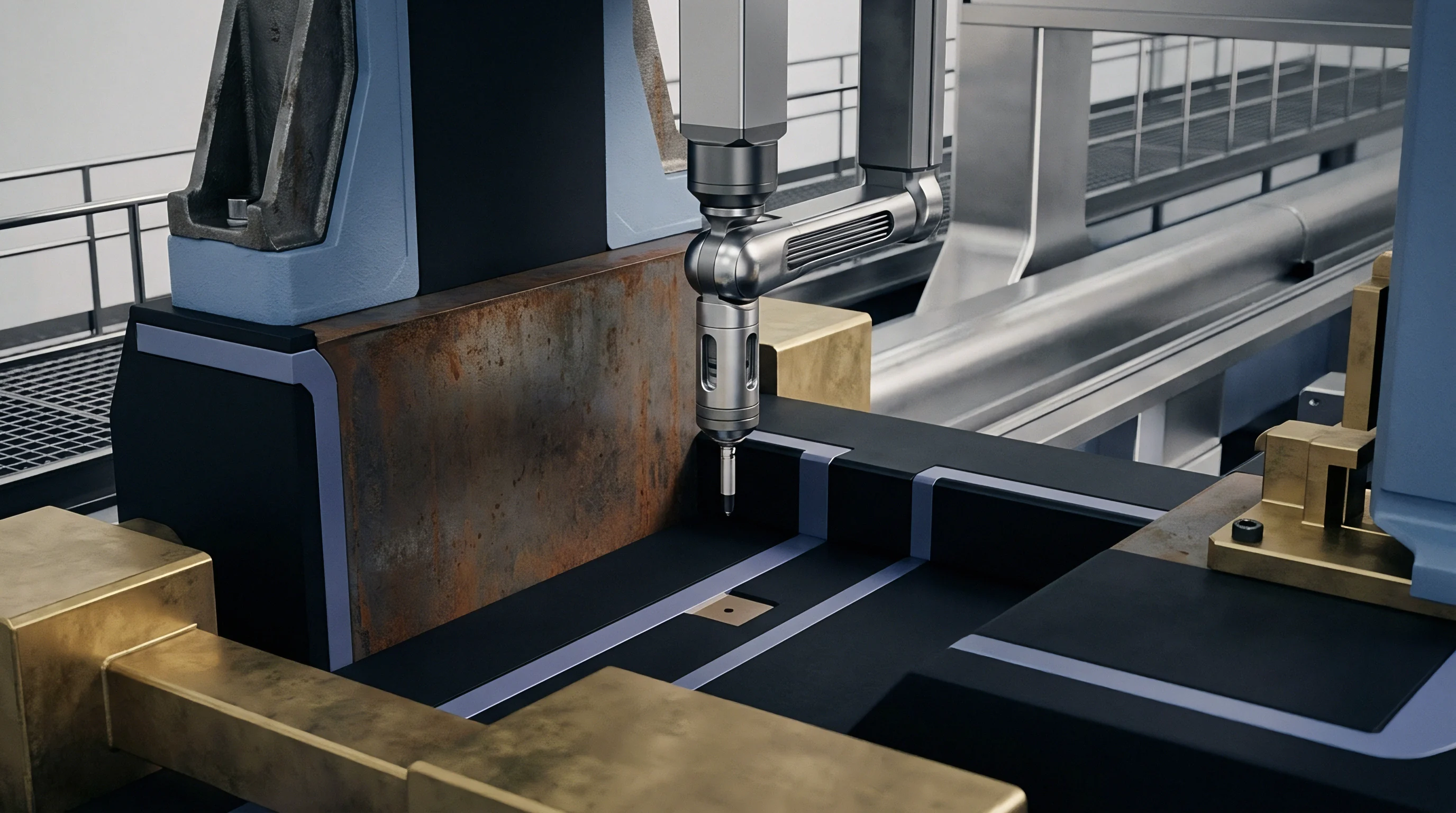
Direct contact conductance cannot be measured with a physical sensor positioned directly at the polymer-steel interface. A thermocouple bead placed flush on the cavity wall disrupts the local thermal field, alters melt flow patterns, and introduces contact resistance artifacts. Measurement relies on inverse calculation.
High-precision subsurface thermocouple arrays embedded inside the tool insert record transient temperature histories, while mathematical inversion algorithms reconstruct the heat flux and surface temperature that occurred at the cavity boundary.
Coaxial fast-response thermocouples provide microsecond response times. These devices feature a central wire insulated from an outer cylindrical sheath by a sub-micron ceramic film, with a vacuum-deposited metallic junction at the sensing tip. Machined flush into the cavity wall, coaxial sensors record temperature swings during the first ten milliseconds of melt impingement.
However, repeated thermal cycling and abrasive melt wear can delaminate the thin-film sensing junction, requiring frequent sensor replacement and recalibration during extended production runs.
Subsurface Thermocouple Array Configuration
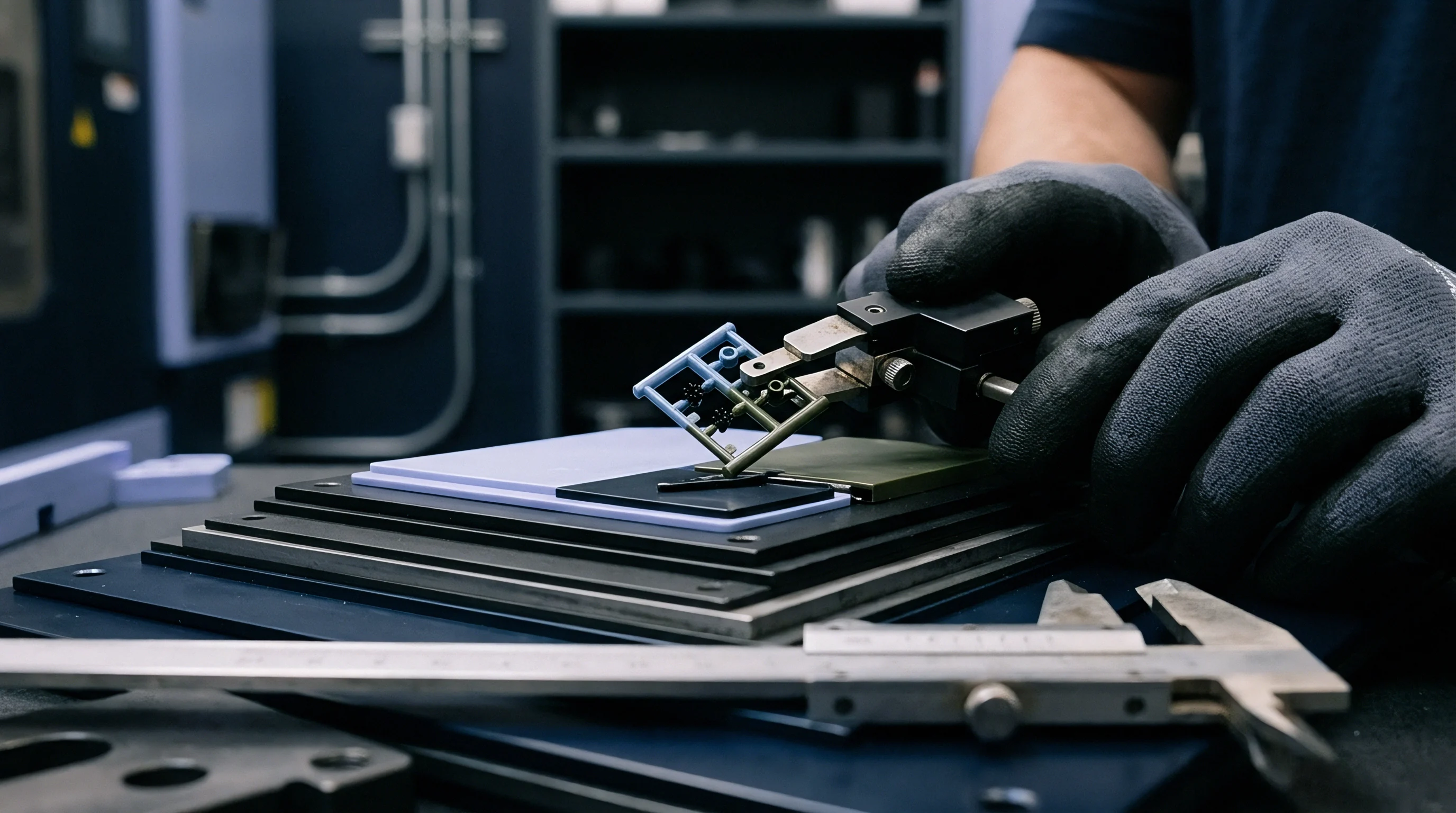
Multi-depth thermocouple arrangements overcome sensor wear by isolating probes beneath the cavity surface. Electric discharge machining cuts micro-bores from the rear of the tool insert, terminating at precise distances such as 0.5 millimeters, 1.2 millimeters, and 2.5 millimeters from the polished cavity face. Spring-loaded mineral-insulated Type K or Type E thermocouples press firmly against the bottom of each flat-bottom hole with consistent preload force.
Distance tolerance governs mathematical stability. A positioning error of 0.05 millimeters in thermocouple depth distorts calculated surface heat flux by up to twenty-five percent during early-stage transient cooling. Coordinate measuring machines equipped with optical probes verify hole depth before sensor installation.
Thermal paste with a certified thermal conductivity above four watts per meter-kelvin fills the sensor tip interface to eliminate parasitic air resistance inside the blind bore.
What Drives Instability in Inverse Conduction Calculations?
Inverse heat conduction problems represent ill-posed mathematical challenges. Small measurement errors or high-frequency electronic noise from injection press motor drives become amplified into wild oscillations in calculated surface heat flux. Beck sequential function specification methods damp these oscillations by using future time steps to regularize the solution.
The algorithm assumes heat flux remains constant over a small future time window, balancing temporal resolution against numerical stability.
Inverse heat conduction algorithms require future-time-step regularization to prevent millivolt thermocouple noise from generating non-physical oscillations in calculated heat flux.
The calculation sequence derives thermal contact conductance step by step:
- Transient temperature recording logs internal steel temperatures and cavity melt pressure at intervals between 0.5 and 1.0 milliseconds.
- Direct conduction modeling solves the one-dimensional heat equation within the tool steel domain using measured subsurface temperatures as inner boundary conditions.
- Surface heat flux estimation applies Beck sequential regularization to project temperature gradients back to the polished tool face.
- Polymer surface temperature derivation pairs calculated heat flux with transient thermal properties of the resin obtained from high-pressure pvT and DSC measurements.
- Conductance extraction divides instantaneous heat flux by the temperature difference between the calculated polymer surface and the calculated tool steel surface.
Failure modes inside the reconstruction chain degrade data integrity:
- Thermocouple tip lift-off occurs when thermal expansion differentials break mechanical contact inside blind sensor holes.
- Noise induction from heater bands corrupts microvolt thermocouple signals when shielding grounds fail near high-current electrical circuits.
- Distorted depth calibration shifts flux curves in time, projecting false delayed conductance peaks that mislead cooling cycle optimization.
- Polymer property drift introduces error when degradation or shear heating shifts the specific heat capacity used in the coupled boundary equations.
The primary uncertainty remains whether the reconstructed heat transfer drop during depressurization stems purely from interfacial air gap growth or involves phase-change recalescence within the crystallizing polymer shell.
Margin
Cooling time consumes seventy to eighty percent of total injection cycle duration. Inaccurate assumptions regarding interfacial conductance ripple directly into machine-hour rates, part unit costs, and tool payback schedules. Quotation models relying on nominal material datasheets assume rapid, uniform heat extraction.
When physical tools enter production trials, real interfacial resistance lengthens the required hold and cooling intervals to prevent dimensional sink and warpage, reducing part output per shift.
| Parameter | Simulation Baseline (Constant HTC) | Measured Tool Reality (Dynamic HTC) | Operational Variance |
|---|---|---|---|
| Contact Conductance (Hold Stage) | 1500 W/(m²·K) | 2100 W/(m²·K) | +40.0% |
| Contact Conductance (Cooling Stage) | 1500 W/(m²·K) | 160 W/(m²·K) | -89.3% |
| Required In-Mold Cooling Time | 8.5 s | 12.2 s | +3.7 s |
| Total Cycle Time | 13.8 s | 17.5 s | +26.8% |
| Parts Produced Per Hour | 2,087 | 1,645 | -442 |
| Annual Machine Hours (1.5M parts) | 718.7 hr | 911.8 hr | +193.1 hr |
| Machine Hourly Rate ($65/hr) | $46,715 | $59,267 | +$12,552 |
| Piece Part Cost Penalty | $0.000 | $0.0084 | +$0.0084 per part |
A cycle extension of 3.7 seconds appears minor on a single shot. Scaled across an annual production contract of 1.5 million parts, that extension adds one hundred and ninety-three press hours. At a standard machine-hour rate of sixty-five dollars for a two-hundred-ton press, the resulting twelve thousand five hundred dollar cost overrun consumes the toolmaker margin on initial cavitation.
The buyer faces either late shipments or requests for tooling revision surcharges to add conformal cooling inserts.
Conformal cooling inserts manufactured via selective laser melting in maraging steel 1.2709 bring cooling channels within two millimeters of the cavity face. However, placing water channels closer to the part yields diminishing returns when interfacial contact conductance collapses. If shrinkage creates a ten-micrometer air gap, the thermal resistance of that air boundary exceeds the conductive resistance of the steel insert.
Investing eight thousand dollars per cavity for additive conformal cooling fails to recover cycle time if packing pressure profiles fail to maintain physical contact between polymer and steel.
Tool transfer disputes frequently trace back to uncharacterized contact resistance. A tool validated in an engineering facility with chilled water at eight degrees Celsius and high hydraulic intensification pressures runs successfully at fourteen seconds. When transferred to a contract production press running cooling water at eighteen degrees Celsius with lower maximum injection pressures, interfacial contact breaks earlier in the cycle.
Parts emerge out of spec across critical DIN 16742 dimensional bands. The production vendor invariably explains that the mold design was flawed from the beginning and that the part cannot be molded within the quoted cycle time without extensive steel rework.