Side Viewing Interferometric Probe Alignment for near Vertical Steel Sidewalls
Aligning side-viewing optical probes on vertical steel sidewalls requires tip-tilt control within 0.05 degrees to preserve coherence fringe visibility.


Ray
Optical path stability inside narrow steel mold slots depends entirely on keeping the probe tip perpendicular to the cavity wall. When scanning deep ribs, micro-channels, or core pin features with draft angles under 0.5 degrees, minor angular misalignment degrades interference signal amplitude. Fiber-based low-coherence interferometry relies on coupling specularly backscattered photons into a single-mode core that often measures less than nine micrometers in diameter.
A tilt of 0.2 degrees redirects the reflected wavefront past the optical collection cone, causing immediate signal dropouts and unresolvable coherence fringes.
Light emerging from a fiber core passes through a miniature turning element to strike the hardened tool surface. In side-viewing configurations, a forty-five-degree micro-prism or polished fiber facet redirects the probe beam sideways into slot geometries as narrow as one millimeter. Toolmakers frequently specify hardened martensitic stainless steels, such as Stavax or 1.2343 hardened to 52 HRC, for these cavity inserts.
High polish finishes create near-specular reflections, meaning beam alignment constraints follow geometric optical tolerances rather than diffuse scattering models.
Angular misalignment exceeding 0.15 degrees on a polished steel sidewalls drops coupled return power by more than 12 decibels when using a 0.12 numerical aperture side-viewing fiber sensor.
When light hits a wall inclined at eighty-nine degrees, the reflected cone shifts away from the collecting lens. The effective numerical aperture of the sensor defines the angular acceptance window. Narrow apertures yield extended depth of field inside deep cavities, yet they restrict the permissible angular tilt during motorized Z-axis traversals.
High-aspect-ratio slots amplify runout errors in stage motion. A mechanical drift of two micrometers over a fifty-millimeter stroke translates into wavefront phase distortion that obscures micro-cracks, electrical discharge machining (EDM) erosion marks, or localized wear on sidewalls.
Aligning the side-looking probe requires continuous tracking of the beam waist location relative to the cavity wall. Position setting procedures establish nominal standoff distance before launching vertical profiling sweeps. If the probe strays outside the Rayleigh range of the focusing optics, beam divergence reduces lateral spatial resolution across the steel face.
- Numerical Aperture Vignetting occurs when the inclined steel surface reflects the outer beam envelope beyond the clear aperture of the micro-prism, truncating spatial frequency data.
- Specular Beam Walk-off forces the return spot off the receiver core center, resulting in complete signal loss over smooth tool steel areas.
- Phase-Front Slant alters the interference path across the sensor beam width, smearing low-coherence fringes and reducing axial profiling precision.
- Multiple Reflection Artifacts arise when light bounces between opposing parallel sidewalls before returning to the receiver aperture, creating phantom surface ghosts in the OCT trace.
Ignoring angular alignment constraints during cavity scanning produces false height profiles that toolmakers misinterpret as wall tapering. Incorrect optical readings lead toolmakers to grind steel off valid mold cores. Scrapped cavity blocks and lost machining hours follow directly from uncalibrated probe trajectories.

Mirror
Reflective turning elements mounted at the tip of narrow optical shafts direct signal paths perpendicular to the probe shaft. Micro-prisms fabricated from fused silica or sapphire are cemented onto single-mode fiber tips using index-matched optical adhesive. The alignment between the fiber core axis and the prism reflector dictates the baseline pointing accuracy of the probe.
Assembly errors as small as thirty arcseconds cause systematic pointing offsets that compound over long slot insertion depths.
Fused silica turning elements attached to single-mode fiber ends provide physical turning geometry inside tight tool recesses. The optical clear aperture of these micro-prisms ranges from 200 to 500 micrometers. Dielectric reflective coatings applied to the hypotenuse face ensure reflectivity over ninety-nine percent across broadband low-coherence light sources centered near 840 or 1310 nanometers.
High reflectivity prevents power losses, maintaining signal-to-noise margins when probing dark or oxidized steel surfaces.
Temperature shifts on the shop floor alter the distance between optical elements and metal outer sleeves. Stainless steel probe housings expand at twelve to sixteen micrometers per meter per degree Celsius, whereas fused silica optics expand at 0.5 micrometers per meter per degree Celsius. Uncompensated thermal expansion shifts the focal spot position along the probe length.
Toolroom inspection cells operating without precise climate controls experience thermal drift that alters probe zero points over a two-hour measurement sequence.
| Tip Architecture | Clear Aperture | Thermal Limit | Lateral Resolution | Angular Tolerance | Unit Cost |
|---|---|---|---|---|---|
| Angle-Polished Fiber Facet | 125 micrometers | 150 degrees C | 12 micrometers | 0.08 degrees | Low |
| Micro-Prism Glued Assembly | 350 micrometers | 80 degrees C | 4.5 micrometers | 0.12 degrees | Medium |
| Monolithic Sapphire Prism Tip | 500 micrometers | 300 degrees C | 3.0 micrometers | 0.25 degrees | High |
| Side-Looking GRIN Lens Array | 1000 micrometers | 100 degrees C | 1.8 micrometers | 0.40 degrees | High |
Mechanical shock during probe insertion into tight mold slots damages optical tip surfaces. Contact with steel sidewalls chips unshielded micro-prism edges, creating light scattering center points that ruin interference fringes. Protective sleeve designs incorporate recessed optical windows or air-purge channels to keep metal filings and cooling oil residues off optical surfaces.
Tooling suppliers frequently claim that side-looking probes operate reliably inside unwashed cavity slots without protective air curtains. Field reality shows oil films and EDM soot accumulate on tip glass within three scan passes, scattering signal paths and degrading coherence fringe visibility.


Fringe
Interferometric measurement relies on combining reference light with light scattered from the cavity wall. Interference fringe contrast defines the precision of surface location algorithms in spectral-domain and time-domain coherence systems. When measuring near-vertical steel sidewalls, surface roughness and tilt angle govern the ratio between specular reflection and diffuse scattering.
Smooth tool steel surfaces yield tight optical return cones, making signal capture sensitive to angular alignment errors.
Low-coherence systems track interference modulation across a localized optical path differential. Coherence envelope detection algorithms identify the peak of the envelope to establish surface z-coordinates. When target inclination angles shift, the interference envelope broadens and drops in amplitude.
Signal processing routines struggle to locate peak position when optical return power drops near the sensor noise floor.
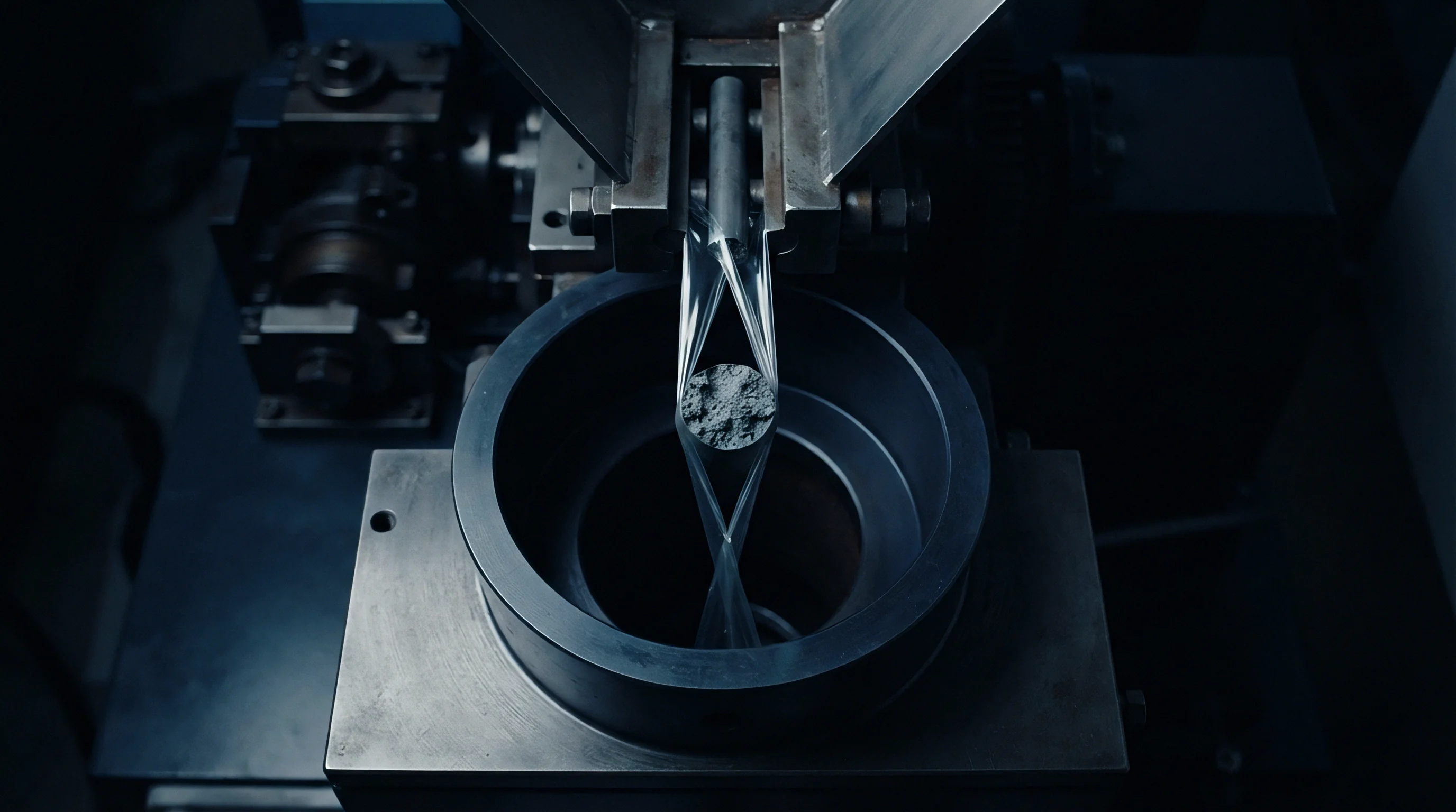
Coherence Envelope Analysis on Inclined Metal Surfaces
Optical return power coupling efficiency models as a function of target tilt angle and optical beam waist radius. Consider a side-viewing interferometric probe with central wavelength 840 nanometers and numerical aperture 0.12, focusing to a beam waist radius of 4.5 micrometers. Target surfaces consist of hardened tool steel with varying tilt relative to probe normal axis.
Coupling efficiency follows a Gaussian drop-off function based on misorientation angle Theta:
Coupling Efficiency = exp( – ( Pi Waist Theta / Wavelength )^2 )
Calculating return power attenuation across three target tilt scenarios demonstrates coupling loss acceleration:
At 0.1 degree tilt (0.001745 radians), misorientation parameter equals 0.02936, yielding coupling efficiency 0.9991, equivalent to 0.004 decibel loss.
At 0.5 degree tilt (0.008727 radians), misorientation parameter equals 0.1468, yielding coupling efficiency 0.9787, equivalent to 0.093 decibel loss.
At 1.2 degrees tilt (0.02094 radians), misorientation parameter equals 0.3524, yielding coupling efficiency 0.8830, equivalent to 0.54 decibel loss.
Surface roughness attenuates the specular return component. Total integrated scatter models specular return reduction based on root-mean-square roughness Sq:
Specular Ratio = exp( – ( 4 Pi Sq cos(Theta) / Wavelength )^2 )
On mirror-polished mold steel with Sq equal to 0.10 micrometers (100 nanometers), Specular Ratio equals exp(-2.238), or 0.1067, causing a 9.72 decibel attenuation. On fine wire-EDM steel surfaces with Sq equal to 0.40 micrometers, specular return drops by 155 decibels, rendering pure specular fringe detection impossible and forcing the sensor to operate entirely on diffuse speckle return.

Would 90 Degree Side Viewing Probes Hold Sub Micron Alignment inside Narrow Tool Cavities?
Maintaining sub-micrometer tracking inside a two-millimeter slot demands dynamic tip control. Spatial drift during vertical axis traversals alters both probe-to-wall distance and angular alignment. Flexure-guided stages with closed-loop optical encoder feedback correct tilt errors in real time, preserving fringe visibility along fifty-millimeter scan runs.
Clause 6.4 of ISO 25178-604 requires optical profiling instruments to document transfer function roll-off across local surface slopes exceeding five degrees.
Fringe contrast declines beyond threshold.
Decibels drop when tilt increases.
Signal processing algorithms must separate genuine surface height variations from slope-induced optical phase shifts. Phase unwrapping errors occur when sudden changes in sidewall draft angle shift local fringe frequencies past the Nyquist sampling limit of the sensor camera array. Optical setup parameters require precise matching to target surface characteristics to prevent signal dropouts during automated tool inspections.
Whether multi-wavelength interferometry can overcome speckle decorrelation on rough EDM sidewalls without sacrificing scan speed remains a contested operational question among toolroom metrology engineers.

Rig
Positioning hardware controls the spatial trajectory of optical sensors lowered into mold slots. Rigidity in the stage stack prevents mechanical vibration from distorting interference patterns. Modern inspection rigs integrate five-axis positioning systems: three linear translation axes (X, Y, Z) and two rotary axes (pitch and yaw).
Direct-drive linear motors coupled with air-bearing slides eliminate stick-slip friction, permitting smooth sub-micrometer step movements inside narrow tool features.
Multi-axis movement tables supply pitch, yaw, roll, and spatial translations during scanning operations. Flexure-based tip and tilt stages mounted near the probe neck handle ultra-fine angular corrections. These piezoceramic-driven stages deliver angular steps below one microradian across a total motion range of two degrees.
Fine angular control permits real-time compensation for core pin tilt or non-vertical slot walls.
Positioning stages require absolute alignment zeroing prior to inserting optical probes into deep cavities.
Mechanical alignment tubes shield delicate fiber assemblies while centering probes within cavity walls. Precision ceramic sleeves made from zirconia or silicon nitride offer high wear resistance and low thermal expansion. Air channels running through the guide sleeve supply clean compressed air at 0.2 megapascal, creating an air-bearing effect that prevents probe contact with steel cavity walls during rapid z-axis profiling strokes.
- Mount the optical probe into the five-axis kinematically decoupled tool holder, securing the outer ceramic guide collar.
- Lower the probe tip into an external zeroing gage containing a polished optical reference flat aligned parallel to the stage motion axes.
- Adjust piezoceramic tilt actuators until signal amplitude reaches maximum back-coupling, establishing optical surface normal orientation.
- Traverse the probe down a certified ten-millimeter ceramic slot standard while recording fringe visibility variations across the Z-axis travel path.
- Apply polynomial motion compensation curves to the motion controller to neutralize systematic mechanical runout errors before scanning production mold inserts.
Positioning stages demand absolute zero.
Air bearings eliminate mechanical friction.
| Stage System Type | Angular Resolution | Travel Range | Thermal Drift Rate | Repeatability | Hardware Budget |
|---|---|---|---|---|---|
| Cross-Roller Bearing Motorized Stage | 5.0 microradians | +/- 5.0 degrees | 0.8 micrometers / hour | 1.2 micrometers | Moderate |
| Piezo-Flexure Tip/Tilt Stage | 0.2 microradians | +/- 0.5 degrees | 0.1 micrometers / hour | 0.05 micrometers | High |
| Air-Bearing Gantry Kinematic Stage | 0.05 microradians | +/- 2.0 degrees | 0.02 micrometers / hour | 0.01 micrometers | Very High |
Guide sleeve clearances must stay under five micrometers to prevent mechanical tilt during vertical probing runs.

Margin
Tooling tolerances on core pins and deep slot inserts govern whether optical sensors can enter without physical contact. High-precision injection molds designed for medical connectors or micro-optics demand dimensional tolerances within TG3 or TG2 classes according to DIN 16742 standards. A cavity slot specified at 1.200 millimeters with a plus-minus two-micrometer tolerance leaves negligible room for probe positioning errors.
Dynamic alignment margins define the spatial envelope available for sensor insertion and tilt adjustment.
Dimensional variations in EDM electrodes compound across deep cavity blocks. Electrode wear causes slot draft angles to drift from nominal 0.5-degree specifications to 0.1-degree near-vertical geometry at the bottom of deep rib pockets. Optical probes must adjust pointing angles continuously along the vertical scan path to match changing wall inclination angles.
A gage repeatability and reproducibility score below ten percent is mandatory for optical cavity inspection systems under ISO 22514-7 qualification protocols.
Quantifying repeat variance across gauge insertions confirms sensor stability on steep tool geometry. Measurement system analysis (MSA) procedures evaluate probe performance across three operators, ten cavity features, and three trial runs. High variability in tilt alignment degrades gauge capability ratios (Cgk), leading toolrooms to reject valid optical measurement setups.
- Core Pin Concentricity errors shift the relative wall distance during rotary probe scanning, consuming optical working distance margins.
- EDM Sidewall Taper Variations alter surface tilt along the slot depth, requiring real-time angular stage corrections during inspection sweeps.
- Thermal Expansion Gradients between core inserts and mold plates alter physical slot dimensions during high-temperature injection trials.
- Clamping Block Distortion compresses cavity sidewalls under pre-load forces, shifting nominal draft angles away from CAD model coordinates.
Tool steel dimensions shift daily.
Gauge variance alters tool life.
Precision machining holds strict limits.
Standard delivery documentation must reference DIN 16742 Tolerance Group TG3 for tool steel cores, establishing permissible dimensional variance limits prior to optical verification sign-offs.
Contract
Commercial agreements for specialized cavity inspection equipment define long-term calibration liabilities. Buying high-precision side-viewing interferometric probes involves strict performance criteria for spatial resolution, signal stability, and optical probe durability. Procurement documentation must spell out explicit acceptable quality limits for probe tip mechanical runout and fringe visibility thresholds before title transfers to the buyer.
Formal delivery protocols mandate specific optical verification before mold steel leaves the shop. Toolmakers must supply full 3D optical point clouds of all near-vertical slot features, certified against calibrated step standards. Raw interferometric fringe data files remain tied to cavity serial numbers, providing an immutable quality audit trail if plastic parts show unexpected sink marks or flash during high-volume production runs.
| Inspection Technology | Scan Speed per Slot | Spatial Resolution | Destructive Test | Equipment Capital Cost | Consumable Cost / Scan |
|---|---|---|---|---|---|
| Side-Viewing OCT Probe | 12 seconds | 2.5 micrometers | No | 120,000 USD | Low |
| Tactile Micro-Stylus CMM | 180 seconds | 1.0 micrometers | No | 250,000 USD | High (Stylus Wear) |
| Destructive Metallurgical Sectioning | 4 hours | 0.5 micrometers | Yes | 15,000 USD | Very High (Scrapped Tool) |
Equipment capital costs write off across production runs when non-contact scanning replaces manual CMM bench work. Reductions in inspection cycle times allow toolrooms to verify every cavity in a 64-cavity connector mold, rather than relying on statistical sampling. Capital payback calculations demonstrate break-even status within nine months of deployment on precision automotive and medical tooling lines.
Tooling sign-offs lock supplier risk.
Scrap rates fall with verification.
Final acceptance clauses link equipment payment schedules directly to passing automated gauge repeatability tests on actual production core inserts. When optical sidewall inspection systems hold sub-micrometer repeatability across three consecutive toolroom shifts, procurement teams release final capital payments to equipment vendors.