Designing Geometrically Balanced Runner Systems for Multi Cavity Tooling
Geometrically balanced runner systems require matched flow lengths, equal hydraulic diameters, and shear-mitigating step-down sizing to yield uniform filling.

Melt
Polymer fluids flowing through cold steel channels experience steep velocity gradients between the stationary outer wall layer and the fast-moving center stream. Molten polymer behaves as a non-Newtonian, shear-thinning fluid. Frictional forces generated by adjacent fluid layers sliding past one another cause the effective viscosity of the material to decrease rapidly under high shear conditions.
Inside a cold runner distribution network, this velocity differential creates two distinct thermal zones within the flow cross-section: an insulating, stationary outer skin and a high-velocity, thermally elevated core stream.
Shear Rate Distribution and Non-Newtonian Rheology
Fluid velocity across a circular feed channel reaches zero at the boundary wall while peaking along the central conduit axis. High injection speeds drive shear rates near the steel interface above several thousand reciprocal seconds. Shear rate scales inversely with the cube of the channel radius for a fixed volumetric throughput.
Shear rate calculation for circular channels follows the expression:
γ = (4 · Q) / (π · r³)
Where Q represents volumetric flow rate and r represents the channel radius. High shear rate regions experience substantial viscosity reduction according to the Cross-WMM or Carreau-Yasuda rheological models. Polymer molecules uncoil and align parallel to the flow direction under intensive shear.
As a result, resistance to flow drops non-linearly in areas of intense shearing while remaining high in the low-shear core zone.
A wall-thickness deviation of 0.05 millimeters across cavity sets increases volumetric shrink variance by 0.4 percent in unfilled polyolefins.
Cold steel freezes outer polymer layers. High injection speeds increase localized shear. Core fluid flows with minimal resistance.
Viscosity drops near the channel walls. Frictional heat generation along the frozen skin interface raises local melt temperature above the barrel setpoint. This localized dissipation of mechanical energy into heat alters the thermal profile of the moving polymer stream before fluid reaches the cavity entrance.

Thermal Layering and Viscosity Variation
High velocity gradients near the channel perimeter convert mechanical energy into localized thermal energy. Heat conduction into the surrounding tool steel continuously cools the outermost layer of polymer. The inner annular ring surrounding the core retains the generated thermal energy because plastics exhibit low thermal conductivity.
A pronounced viscosity gradient develops across the channel cross-section as a consequence of this temperature variation. Fluid in the high-shear, elevated-temperature layer exhibits significantly lower viscosity than fluid in the central core.
When the feed stream reaches a branch junction, any asymmetrical splitting of these thermal layers creates uneven flow resistance in downstream channels. A branch receiving a higher proportion of the shear-heated material experiences reduced hydraulic resistance. That branch accepts a higher flow rate than an adjacent branch receiving cooler, higher-viscosity material.
Thermal layering governs local hydraulic impedance throughout the runner tree. Improper management of thermal shear gradients leads to severe dimensional skew across cavity clusters, causing non-conforming part dimensions that fail assembly tolerances after thermal relaxation.

Layout
Symmetrical channel arrangements direct fluid through identical path lengths to deliver equal volumetric flow to every cavity gate simultaneously. Runner geometry establishes the physical baseline for multi-cavity tool performance. Symmetrical layouts ensure that pressure drop, flow velocity, and cooling exposure remain mathematically identical from the main sprue landing to each individual gate entry.
Geometric Balance and Path Length Symmetry
Equal flow distances across branching paths prevent premature packing in central cavities. Naturally balanced systems maintain identical runner lengths, identical channel diameters, and identical turn angles for every flow path. H-pattern, radial spider, and octagonal layouts represent naturally balanced configurations.
In an H-pattern layout, fluid splits at primary, secondary, and tertiary branches with uniform geometry, ensuring synchronized cavity filling under ideal laminar conditions.
Symmetrical geometry prevents unequal flow arrival. Fishbone and ladder layouts fail to achieve natural balance. In a fishbone runner layout, fluid reaches the inner cavities long before reaching the outer cavities.
Artificially balancing a fishbone layout through restrictive sizing of inner runners introduces severe process sensitivity. Artificially sized channels restrict flow at a single viscosity and injection speed point. Shifts in injection velocity, melt temperature, or material batch viscosity disrupt the artificial balance, resulting in flash on inner cavities or short shots on outer cavities.

Feed Channel Cross Section Profiles
Cross-sectional shape governs hydraulic efficiency and runner mass. Maximizing the ratio of cross-sectional area to perimeter surface area minimizes pressure loss and thermal dissipation into the tool block.
- Full round runner channels offer the maximum ratio of cross-sectional area to perimeter surface, minimizing thermal loss and pressure drop during filling.
- Modified trapezoid cross sections allow single-plate machining while maintaining ninety percent of the hydraulic efficiency of full round profiles.
- Standard trapezoid profiles increase frictional drag along the flat base, requiring wider draft angles to prevent ejection sticking during tool opening.
- Parabolic feed channels reduce runner mass near the gate landing, though depth tolerances dictate local pressure drop variance.
Circular runners maximize hydraulic efficiency. Feed channel volume adds directly to cycle time. Draft angles assist clean runner ejection.
Machining full round runners requires matching halves cut into opposing mold plates, demanding pin alignment tolerances within 0.01 millimeters to avoid parting line flash or stepped channel steps.
| Geometry Profile | Hydraulic Radius Ratio | Machining Requirement | Pressure Drop Penalty | Ejection Reliability |
|---|---|---|---|---|
| Full Round | 1.00 | Two Mold Plates | Baseline (Lowest) | High |
| Modified Trapezoid | 0.88 | Single Mold Plate | +12 Percent | High |
| Standard Trapezoid | 0.74 | Single Mold Plate | +28 Percent | Moderate |
| Parabolic Profile | 0.79 | Single Mold Plate | +22 Percent | High |
Selecting a modified trapezoid profile reduces tooling cost by restricting runner machining to a single mold plate. The flat base of the modified trapezoid incorporates a 5-degree side draft with a fully radiused floor, offering a practical compromise between hydraulic efficiency and toolmaking complexity. Primary runner channels extend beyond the final branch intersection to create a cold slug collector that captures the chilled leading edge of the polymer stream before fluid enters the cavity gate.


Branch
Splitting a primary flow channel into secondary tributaries divides the thermal cross-section of the moving polymer melt unevenly. Symmetrical runner geometry does not guarantee symmetrical rheological behavior. As non-Newtonian polymer flows through a 90-degree runner elbow, the high-shear, low-viscosity outer skin layer shifts toward the inner radius of the corner.
Upon entering the secondary branch, this hotter layer concentrates on one side of the channel, while the cooler core material aligns along the opposing wall.

Can Shear Imbalance Be Corrected without Modifying Steel?
Adjusting injection velocity profiles alters the magnitude of frictional heating across channel junctions. Higher injection speeds increase shear heating, magnifying the temperature difference between the inner and outer flow laminates. Lowering injection speed reduces shear intensity, which narrows the thermal gap across the branch split.
However, process adjustments cannot eliminate the fundamental physical asymmetry produced by non-planar fluid turns. Altering injection speed shifts the filling balance point between cavity sets without achieving uniform volumetric fill across all processing windows.
Asymmetrical thermal profiles created by high shear rates produce uneven cavity filling rates despite identical physical runner lengths.
Fluid turns generate asymmetric thermal profiles. Outer cavity gates receive hotter polymer. Viscosity splits unevenly at T-junctions.
Rheological rotation restores thermal symmetry. In an 8-cavity geometrically balanced H-runner tool, the four inner cavities receive polymer carrying a higher thermal energy content than the four outer cavities. The inner cavities fill faster and pack to a higher density, generating part weight variations between cavity positions despite identical tool dimensions.

Symmetrical Rheological Rotation Mechanics
Installing flow-reorienting core inserts at branch intersections redistributes hot high-shear skin layers into central stream positions. Melt-flipping technologies split the flow stream and physically rotate the laminates 90 degrees at the branch point. This rotation places equal amounts of hot and cold polymer on both sides of subsequent channel splits.
Secondary and tertiary branches then receive thermally balanced melt streams, ensuring uniform filling rates across all cavities regardless of position in the tool layout.
Symmetrical rheological distribution prevents localized sink marks, flash, and warpage stemming from uneven cavity packing pressures. Tooling vendors frequently attribute outer cavity short shots to minor injection speed variations or localized steel temperature fluctuations rather than addressing asymmetric shear heating in the runner manifold.
Sizing
Calculating channel diameters across multi-level distribution trees balances pressure drop penalties against total shot volume. Runner diameter selection must maintain controlled melt velocity while avoiding excessive shear rates or extended cooling times. Oversized runners increase material scrap and extend cycle times.
Undersized runners demand extreme injection pressures, causing polymer degradation and mechanical press wear.

Step down Ratios and Volumetric Continuity
Main distribution channels split fluid into tributary branches using empirical reduction ratios based on volumetric continuity. When a primary runner splits into two equal secondary runners, maintaining constant average fluid velocity requires reducing the secondary runner cross-sectional area. The classical volumetric step-down relationship dictates that secondary channel diameter equals primary diameter divided by the cube root of two:
d_secondary = d_primary / (2^(1/3)) ≈ 0.793 · d_primary
Applying this rule maintains consistent shear rate levels across branch transitions. Sizing tertiary channels follows the same step-down factor relative to secondary channels. Deviating from this ratio alters fluid velocity and shear rate, causing thermal shifts in downstream branches.
- Calculate total volumetric flow rate required to fill all cavities within target fill time.
- Determine primary runner channel diameter to maintain shear rates between 1000 and 10000 inverse seconds.
- Apply step-down sizing ratio of one over cube root of two to calculate secondary runner diameter.
- Verify pressure drop across network using Hagen-Poiseuille relationship modified for power-law fluids.
- Adjust tertiary channel dimensions to match calculated pressure drop across all gate entry points.

Pressure Drop and Velocity Control
Frictional losses along narrow feed lines escalate rapidly as channel radii decrease. Pressure drop in circular channels varies inversely with the fourth power of the radius for Newtonian fluids, and inversely with the power-law index exponent for pseudoplastic polymers. Smaller diameters increase pressure requirements.
Flow velocity accelerates through branches. Excessive runner volume wastes raw material.
Consider an 8-cavity tool molding an acrylonitrile butadiene styrene component. Total part volume equals 120 cubic centimeters across eight cavities. The runner system spans a primary branch length of 100 millimeters, two secondary branch lengths of 80 millimeters, and four tertiary branch lengths of 40 millimeters.
Assuming an injection time of 1.2 seconds, volumetric flow rate equals 100 cubic centimeters per second through the primary runner.
DIN 16742 Group TG4 dimensional tolerances apply only when peak cavity pressure variation between opposing cavities remains under 3.5 bar.
| Branch Level | Nominal Diameter (mm) | Flow Velocity (mm/s) | Shear Rate (1/s) | Pressure Drop (bar) |
|---|---|---|---|---|
| Primary (1 segment) | 8.00 | 1989 | 1989 | 42.5 |
| Secondary (2 segments) | 6.35 | 1577 | 1987 | 38.1 |
| Tertiary (4 segments) | 5.00 | 1273 | 2037 | 29.4 |
| Calculated assuming ABS polymer at 240 degrees Celsius melt temperature and 100 cubic centimeters per second injection rate. | ||||
Calculated total pressure drop across the runner system reaches 110.0 bar. Primary diameter sizing at 8.00 millimeters keeps shear rates near 2000 inverse seconds, preventing thermal degradation while maintaining acceptable pressure transmission to the gates. Whether adaptive process controls on modern presses can fully compensate for runner shear skew without physical flow-deflection inserts remains a subject of ongoing press-side investigation.
Verification
Qualifying flow balance across multi-cavity tooling demands structured press-side sampling under controlled injection velocity profiles. Tool trials confirm whether theoretical runner designs deliver physical volumetric flow balance. Evaluating real-world balance requires decoupling the filling phase from the packing phase to isolate runner hydraulic resistance from gate freezing behavior.
Progressive Short Shot Studies
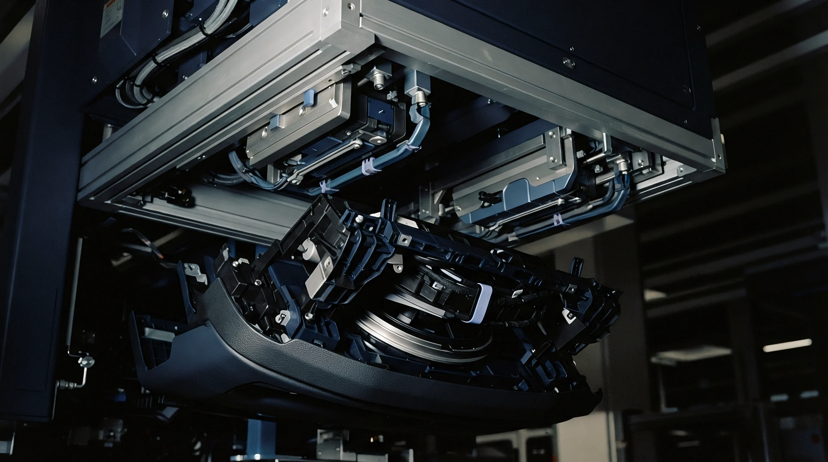
Stepwise volumetric fill shots reveal actual physical flow front progression across cavity networks. The press operator reduces stroke volume to fill 10 percent of total part volume, increasing stroke in increments up to 95 percent fill without initiating pack or hold pressure. Short shots reveal actual flow fronts.
Weight variation indicates cavity imbalance. Pressure transducers capture dynamic packing curves. Equal hold times prevent sink marks.
- Short shot fill spread measures the physical percentage fill divergence between the fastest and slowest filling cavities during a ninety percent fill trial.
- Pressure peak divergence identifies thermal or physical channel restrictions by comparing sensor telemetry across opposing cavity locations.
- Gate freeze timing variance determines packing duration requirements by tracking individual cavity part mass across increasing hold time increments.
A geometrically balanced system exhibits a fill spread below 2.0 percent at 90 percent volumetric fill. Higher fill spread percentages indicate channel machining errors, uneven mold temperature distribution, or rheological shear imbalance across branches.
Cavity Weight and Pressure Monitoring
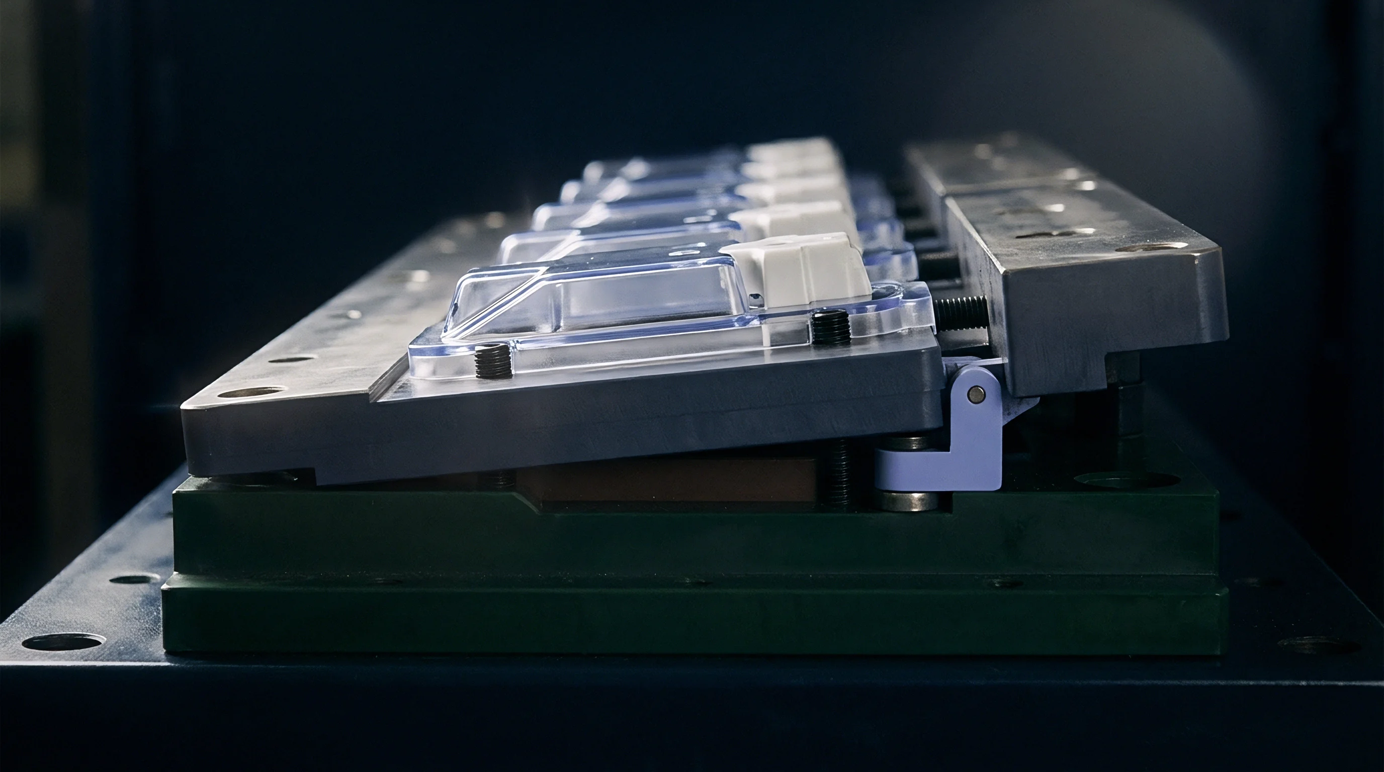
Weighing individual parts from a full-shot mold trial quantifies filling uniformity across cavity positions. Sampling fifty consecutive full-pack shots provides the statistical dataset necessary to calculate coefficient of variation across cavity positions. Standard deviation divided by mean part mass defines cavity weight variation.
Precision tooling targets a weight coefficient of variation below 0.5 percent across all cavities.
Core pins shift under unequal cavity filling pressures, creating wall thickness variation across multi-cavity tools.
Piezoelectric pressure sensors installed directly behind cavity ejector pins capture dynamic pressure distribution throughout injection, packing, and cooling phases. Peak pressure variation between cavity locations directly correlates with dimensional variance in finished components. Sourcing contracts incorporating ISO 294-1 balance clauses stipulate that cavity-to-cavity weight variation remains within 1.5 percent across a 50-shot qualification run before tool sign-off is granted.

Yield
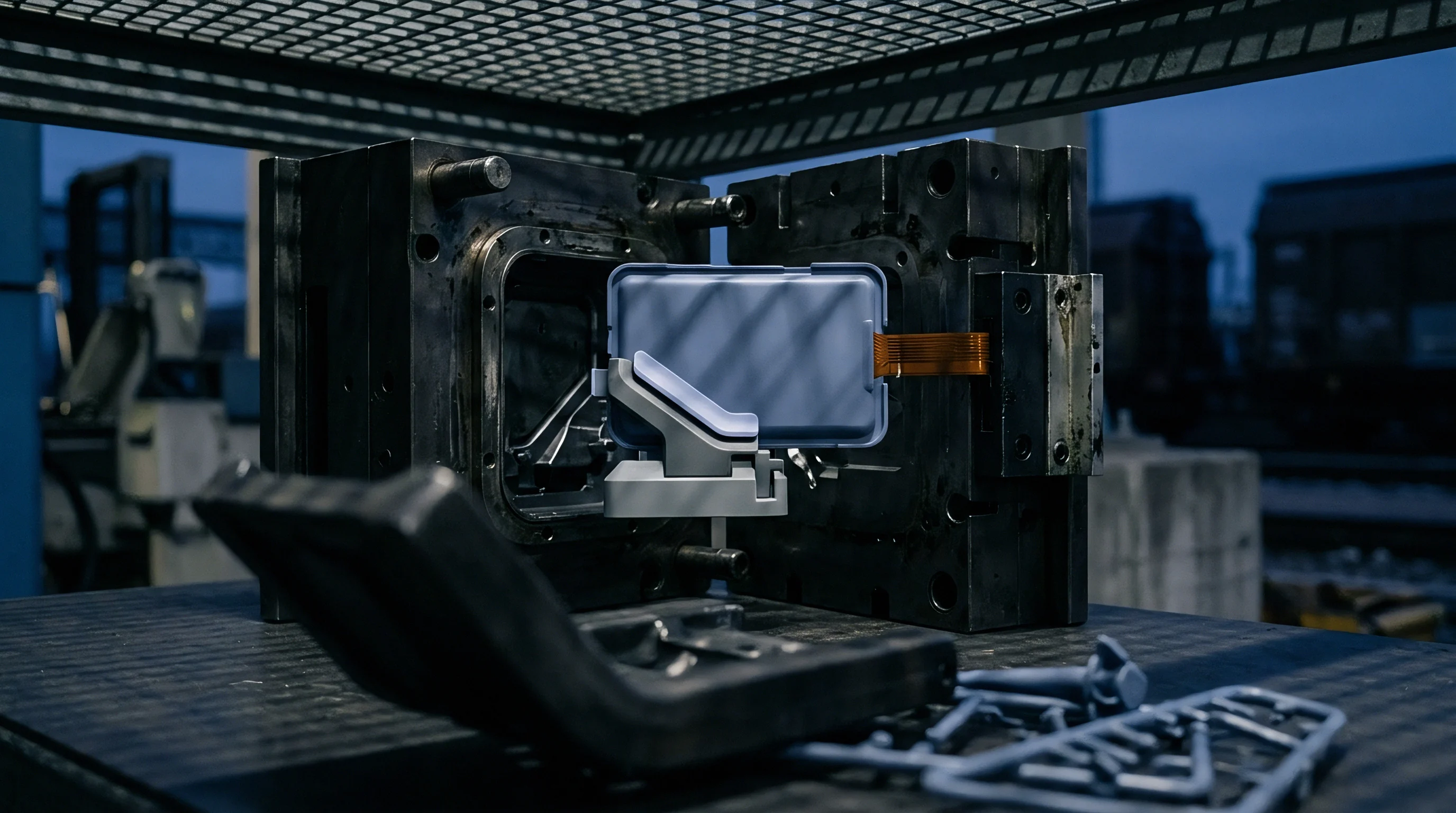
Tooling economics depend directly on the mass ratio between the distribution network and the finished moulded components. Cold runner channels represent scrap material that requires granulating, blending, or disposal. Managing runner mass ratio preserves resin integrity and optimizes clamp force usage on the molding press.

Cold Runner Scrap and Regrind Amortization
Excessive feed volume increases raw material cost per part when regrind limits restrict scrap re-introduction. Runner mass exceeding 20 percent of total shot mass imposes a severe financial penalty in high-volume production. High regrind ratios alter polymer molecular weight distribution through repeated heat histories, reducing tensile strength and impact resistance in critical components.
Runner volume dictates cooling duration. Regrind degrades thermal properties over cycles. Hot manifolds eliminate cold scrap completely.
Tooling capital outlays demand high production volumes. Thick primary runners often dictate minimum cooling time, extending overall cycle duration even when part wall thickness allows faster cycle rates. Thick runner sections cool slower than thin part walls, forcing the press to remain closed solely to solidify feed channels for clean ejection.

Hot Runner Manifold Conversion Thresholds
Replacing cold feed channels with heated manifold systems eliminates runner scrap while elevating initial tooling capital outlays. Heated manifolds maintain polymer in a molten state up to the cavity gate entrance. Converting to hot runner tooling removes runner cooling time from cycle calculations, increasing hourly part output.
| Feed System Architecture | Initial Tooling Cost Impact | Cycle Time Efficiency | Material Scrap Rate | Break-Even Production Volume |
|---|---|---|---|---|
| Naturally Balanced Cold Runner | Baseline | Baseline (Cooling Limited) | 15 to 35 Percent | Under 100,000 Units |
| Artificially Sized Cold Runner | +10 Percent | Baseline (Cooling Limited) | 10 to 25 Percent | 50,000 to 150,000 Units |
| Open-Sprue Hot Runner | +45 Percent | +20 Percent Speedup | Near Zero | 250,000 to 500,000 Units |
| Valve-Gated Hot Manifold | +85 Percent | +35 Percent Speedup | Zero | Over 750,000 Units |
Calculating the break-even volume for hot runner conversion weighs initial tool capital against material savings and press operational hour reductions. High-cost engineering resins lower the conversion threshold volume significantly. Evaluating total part production volume against the amortized tooling surcharge establishes the exact financial crossover point where heated manifold systems outperform cold runner networks.