Closed Loop Cavity Pressure Control Implementation for Multi Cavity Tools
Closed loop cavity pressure control isolates part dimensions from material viscosity shifts by triggering transfer and regulating packing directly from cavity telemetry.

Sensor
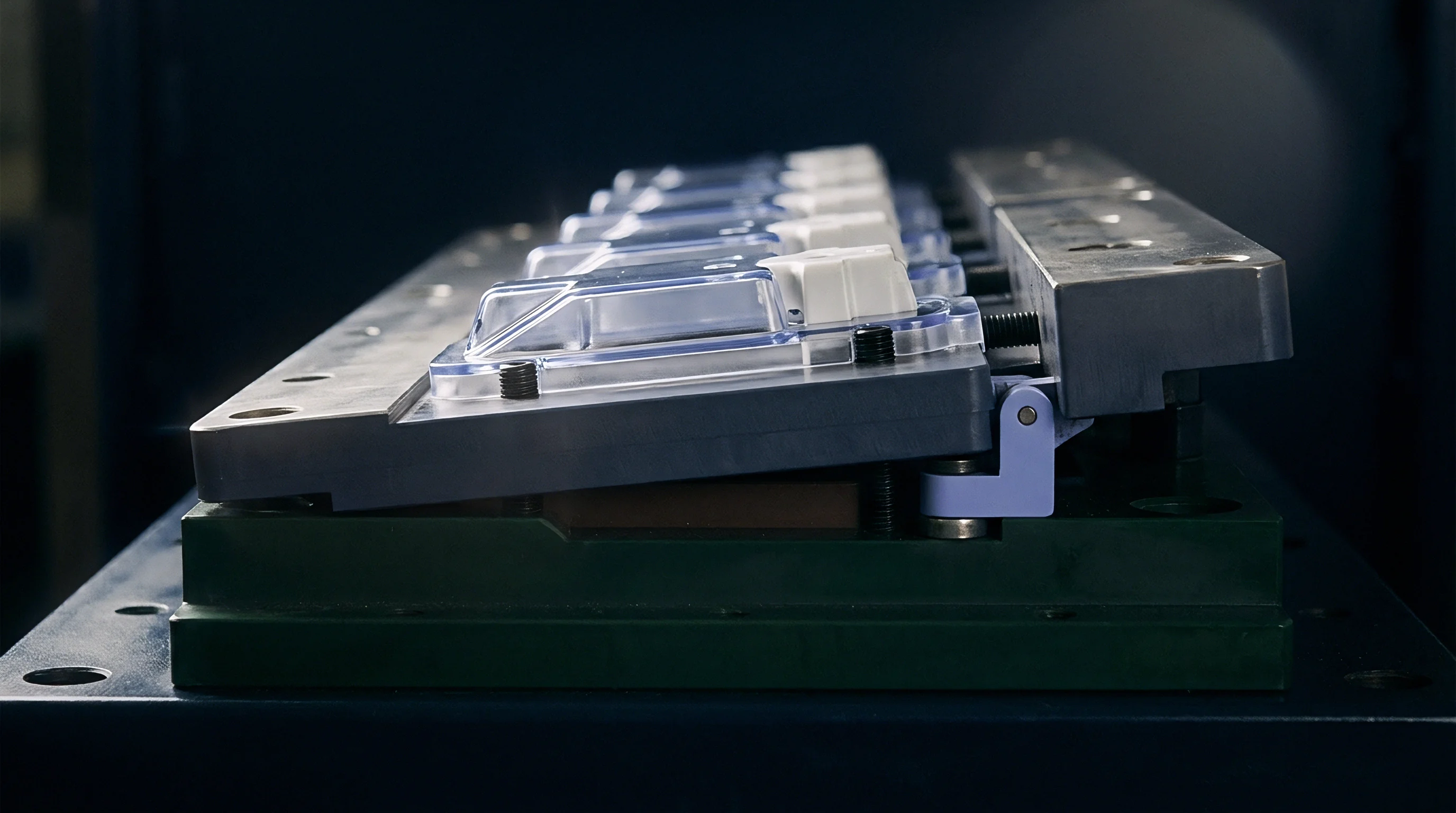
Piezoelectric crystals generate an electrical charge proportional to applied mechanical force when molten polymer enters the impression. Installing transducers directly inside the mould cavity wall captures the true hydrostatic pressure of the melt stream without mechanical loss. Direct measurement delivers response times under one millisecond, enabling precise signal capturing during the fast fill phase of injection.
High-cavitation tooling demands miniature quartz transducers with housing diameters between two and three millimetres to fit tight cavity pitch layouts without interfering with cooling channels or ejector sleeve assemblies.
Indirect installation positions the transducer beneath an ejector pin or dummy force-transmission pin inside the ejector plate. Load pins transfer cavity force directly to the quartz element, isolating sensitive electronics from melt contact and extreme thermal shock. Pin friction, deflection, and mechanical binding reduce dynamic measurement accuracy by four to twelve percent compared to direct flush mounting.
Machine setters compensate for pin binding through routine zero-point re-calibration before starting automated production runs.

Direct Positioning at Critical Flow Locations
Placement of the transducer near the end of fill detects short shots, sink marks, and flash conditions. Positioning the sensor near the gate captures switchover pressure spikes and peak packing levels. Precision tools housing complex geometries incorporate two sensors per cavity to calculate real-time melt front velocity and viscosity changes across the flow length.
Multi-cavity tools running technical components require at least one reference cavity fully instrumented to control machine switchover functions.
A 50-bar cavity pressure drop during fill switchover increases volumetric shrinkage in semi-crystalline polymers by up to 0.4 percent.
Signal amplifiers positioned on the top clamp plate convert high-impedance pico-coulomb charge outputs into robust voltage signals before cable routing reaches the press controller. Charge amplifiers set to narrow operating ranges increase signal-to-noise ratios during low-pressure packing phases. Digital charge amplifiers mounted on the tool frame eliminate electrical noise picked up along long umbilical cables connected to the press controller.

Indirect Pin Mechanics and Preload Calibration
Force transmission through ejector pins relies on exact machining tolerances to avoid sensor overload during tool clamping. Preloading the transducer with three to five kilonewtons of axial mechanical force maintains continuous contact between the pin end and sensor diaphragm. Insufficient preload creates signal dead bands during the initial melt filling phase, distorting pressure integral calculations used for inline part sorting.
| Sensor Design Type | Pressure Range (bar) | Frequency Response (kHz) | Thermal Limit (°C) | Mounting Footprint (mm) |
|---|---|---|---|---|
| Direct Piezoelectric Quartz | 0 to 2500 | 100 | 300 | 2.5 to 4.0 diameter |
| Indirect Load Pin Transducer | 0 to 2000 | 20 | 200 | 6.0 to 12.0 diameter |
| Thick-Film Strain Gauge | 0 to 1500 | 5 | 180 | 8.0 to 15.0 diameter |
Thermal expansion of long ejector pins causes baseline signal drift during extended moulding shifts. Toolmakers mitigate thermal drift by applying ceramic insulation sleeves around transmission pins passing through heated runner plates. Moulders frequently cite sensor manufacturer statements asserting that indirect sensors remove cavity modification risks while ignoring calibration errors caused by pin friction and flash ingress into pin clearances.
Decoupling
Decoupled moulding isolates the volumetric filling phase from the pressure-driven packing phase to stabilize part density. Phase one fills 95 to 98 percent of the total cavity volume under fast velocity control without machine hydraulic backpressure intervention. Transferring to phase two packing occurs at the exact microsecond cavity pressure reaches a predetermined threshold, eliminating reliance on screw position or hydraulic system pressures.
Closed-loop switchover driven by cavity pressure sensors prevents short shots caused by viscosity fluctuations across material lots. Polymer melt viscosity shifts up to twenty percent between virgin resin batches or regrind blends. Screw position switchover fails to compensate for viscosity drops, resulting in overpacking and flash.
Cavity pressure switchover dynamically adjusts injection hydraulic pressure, holding part weight constant despite material lot variation.

Cavity Pressure Switchover Mechanics
Peak pressure switchover triggering transmits a digital signal directly to the machine hydraulic valve driver within two milliseconds. Screw forward speed decelerates instantly, preventing pressure spikes that stress cavity inserts and cause flash. Multi-cavity tools utilize peak pressure signals from the slowest-filling cavity to trigger machine pack transfer, ensuring complete filling across all impression channels.
Closed-loop pressure control during the hold phase actively regulates hydraulic or servo-electric ram force using continuous feedback from cavity sensors. Machine controllers adjust output voltage to match a defined cavity pressure profile across time. Constant cavity pressure during cooling prevents void formation in thick wall sections and reduces directional sink marks on cosmetic surfaces.
Dynamic Valve Gate Response Times
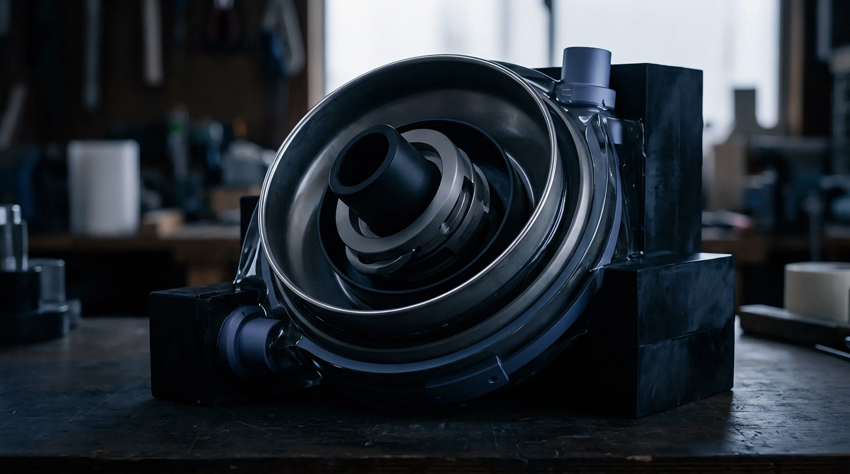
Dynamic valve gate systems adjust needle positions inside hot runner nozzles based on real-time cavity pressure telemetry. Fast-acting pneumatic or servo-electric actuators drive valve needles closed individual cavity by individual cavity as each reaches peak packing target. Dynamic gate closure prevents overpacking in early-filling cavities while later cavities complete their filling sequence.
- Viscosity thermal sensitivity alters melt resistance inside runner channels during extended machine stops, producing short shots on restart.
- Check valve leakage allows resin backflow past the screw tip during high-pressure injection, reducing delivered volumetric shot size.
- Thermal expansion drift shifts mold plate geometry, causing variable gate restriction and unbalancing fill speeds across impressions.
- Hydraulic fluid warming reduces pump volumetric efficiency over an eight-hour shift, dropping actual screw stroke speed.
Dynamic valve gate control decouples individual cavity pressure profiles from machine hydraulic pressure limitations entirely. Individual pressure regulation compensates for geometric runner imbalance across 16-cavity and 32-cavity tools. Switchover triggering on cavity pressure rather than screw position insulates part dimensions from batch-to-batch resin viscosity variations.


Symmetry
Geometric symmetry in runner layouts fails to guarantee identical volumetric filling rates across all cavities. Non-uniform shear heating inside runner channels causes viscosity distribution gradients between inner and outer cavity groups. Melt flowing through runner tees experiences asymmetric shear rates, leading to higher core temperatures and lower viscosity in specific downstream cavities.
Thermal variations across large mould tool plates exacerbate filling imbalance. Cooling channel fluid temperatures vary up to five degrees Celsius between inlet and outlet manifold ports, altering local steel temperatures and polymer flow resistance. Closed-loop pressure control counteracts thermal and rheological imbalance by regulating individual cavity packing durations using real-time telemetry.

Rheological Causes of Cavity Imbalance
Melt flow imbalance alters internal stress distribution, warp behavior, and final part dimensions across high-cavitation tools. Uncontrolled multi-cavity tools yield dimensional spreads three to five times wider than single-cavity prototype tools. Installing closed-loop cavity pressure hardware reduces cavity-to-cavity weight variance below 0.5 percent across 32-cavity production tools.
Tooling purchase contracts specifying DIN 16742 Tolerance Group TG4 mandate real-time cavity pressure telemetry across all active cavities during qualification runs.
Active manifold temperature regulation uses cavity pressure data to adjust individual nozzle tip heater zone setpoints dynamically. Raising tip temperature lowers local melt viscosity, accelerating flow into lagging cavities. Lowering tip temperature increases flow resistance, restricting early-filling impressions to equalize cavity pressure rise rates across the tool.

Independent Cavity Pressure Regulation Architecture
Valve gate timing controllers process individual cavity transducer signals to actuate gate pins independently. As each cavity achieves its target pressure profile, its corresponding valve gate closes instantly, stopping melt flow while adjacent cavities continue filling. Independent gate control isolates each cavity, turning a multi-cavity tool into an array of independently controlled single-cavity moulds.
| Cavity Number | Fill Time At 95% (s) | Peak Pressure (bar) | Part Weight (g) | Dimensional Variance (mm) |
|---|---|---|---|---|
| Cavity 1 | 0.42 | 580 | 14.21 | +0.012 |
| Cavity 2 | 0.41 | 582 | 14.22 | +0.010 |
| Cavity 3 | 0.44 | 578 | 14.19 | -0.008 |
| Cavity 4 | 0.43 | 581 | 14.20 | +0.002 |
| Cavity 5 | 0.42 | 579 | 14.21 | +0.005 |
| Cavity 6 | 0.45 | 577 | 14.18 | -0.014 |
| Cavity 7 | 0.41 | 583 | 14.23 | +0.015 |
| Cavity 8 | 0.43 | 580 | 14.20 | +0.000 |
High-speed data acquisition cards sample cavity pressure signals at rates up to two kilohertz per channel. Fast sampling prevents signal aliasing during brief pressure spikes associated with valve gate closing events. Controller logic applies moving average filters to suppress high-frequency electrical noise generated by nearby mold heater bands and servo drives.
Uncorrected thermal and pressure imbalances cause premature ejector pin wear, flash on early-filling cavities, and dimensional scrap across high-cavitation tooling.
Audit
Design of experiments methodology establishes robust processing windows by correlating peak cavity pressure and pressure integral (Pint) values directly to physical part quality attributes. Testing runs vary injection velocity, hold pressure, and melt temperature across systematic bounds while capturing full pressure curves. Quality engineers extract peak pressure values and curve areas to map process capabilities against drawing tolerances.
Statistical process control uses the cavity pressure integral as a real-time proxy for part density, weight, and critical dimensions. Pressure integral calculations sum sensor bar readings over the packing and cooling duration in millisecond increments. Upper and lower control limits placed around the target integral value trigger automated press-side part rejection gates, isolating non-conforming mouldings instantly.
Capability Indices Derived from Pressure Integrals
Process capability indices (Cp and Cpk) evaluated on peak cavity pressure reflect real process stability better than machine hydraulic monitoring. A stable process holds peak pressure variation within a three-sigma band narrower than five percent of the nominal target value. Achieving Cpk values above 1.67 requires tight control over cavity packing pressure, cycle time consistency, and mold temperature stability.
- Mount cavity transducers into cleaned tool cavities, torqueing lock nuts to specified installation values.
- Connect signal cables to charge amplifiers, verifying channel assignment maps against tool layout drawings.
- Execute auto-zero routines on signal amplifiers with the mold open to purge baseline voltage drift.
- Perform a short-shot study under velocity control to identify mechanical runner filling imbalances.
- Establish peak cavity pressure switchover thresholds, tuning transfer timing to eliminate pressure spikes.
Signal area under the cavity pressure curve provides a direct proxy for final part weight and volumetric density.
Real-time telemetry overlays active pressure curves against a qualified master template stored in memory. Envelopes bounded by upper and lower pressure limits flag process anomalies such as clogged gate inserts, broken valve pins, or heater band failures. Press controllers stop automated cycling when five consecutive shots cross defined alarm boundaries.
Scientific Process Window Definition
Process window qualification defines the maximum allowable variation in melt temperature and injection speed that maintains acceptable cavity pressure profiles. Moulders document window limits on process sheets to enforce repeatable tool setups across different moulding machines. Closed-loop control expands the usable process window by automatically adjusting hydraulic pressure to absorb environmental temperature shifts.
Compliance with ISO 294-1 clause 5.3 obliges process engineers to document cavity pressure profiles during specimen moulding to validate structural test repeatability.

Economics
Commissioning closed-loop cavity pressure hardware requires substantial initial capital investment in sensors, charge amplifiers, software interfaces, and specialized hot runner controllers. A 32-cavity tool requires thirty-two individual sensors, multi-channel amplifiers, and custom plate machining, adding $45,000 to $70,000 to base tool construction charges. Cost justifications rely on scrap reduction, cycle time compression, and automated inline quality assurance.
Scrap reduction delivers immediate financial payback in high-volume medical, cap, and technical component moulding. Open-loop high-cavitation tools experience scrap rates between two and five percent due to short shots, flash, and sink defects. Closed-loop pressure control lowers scrap rates below 0.1 percent, saving tens of thousands of dollars in wasted resin and machine capacity annually.
Tooling Amortisation Mechanics
Tooling payback calculations set initial capital expenditure against unit cost savings over the planned production volume. A worked comparison evaluates a 32-cavity tool producing 20 million medical housings per year on a 300-tonne electric injection moulding machine with a $95 per hour operating rate. The base part weight is 4.5 grams, molded from medical-grade polycarbonate priced at $4.20 per kilogram.
Under open-loop control, a 2.5 percent scrap rate generates 500,000 defective parts per year, wasting 2,250 kilograms of resin valued at $9,450. Scrap sorting and secondary inspection add 120 machine-hours of wasted production time, costing $11,400 in lost machine availability. Total annual scrap cost under open-loop control reaches $20,850.
Closed-loop pressure control implementation reduces the scrap rate to 0.05 percent, yielding 10,000 defective parts per year and cutting scrap cost to $417 annually. Annual operational savings total $20,433. Deducting $2,000 for annual sensor calibration and cable replacement leaves a net annual saving of $18,433.
Against an initial sensor integration outlay of $52,000, the closed-loop system achieves full capital amortisation in 2.8 years.
Decision Checklist for Tool Commissioning
- Part tolerance severity determines whether drawing dimensions demand real-time cavity pressure regulation or basic machine position switchover.
- Resin cost volatility elevates financial risks associated with scrap generation, shortening payback periods for sensor installations.
- Cavitation density limits restrict physical sensor installation options in ultra-compact mold designs running micro-moulded components.
- Quality compliance mandates require 100 percent inline part tracing and data logging for automotive and implantable medical components.
Cycle time compression provides additional operational economic gains. Precise detection of gate freeze using cavity pressure decay profiles allows setters to trim cooling times by two to four seconds per shot. Saving three seconds on a 15-second cycle time increases annual tool production capacity by twenty percent without purchasing additional presses.
The long-term operational question remains whether sensor drift over tens of millions of cycles warrants automated auto-zero re-calibration algorithms embedded directly into press controllers.


Architecture
Signal wiring design inside multi-cavity mould plates protects high-impedance cabling from pinch hazards, moisture, and electromagnetic interference. Cable channels machined into core and cavity plates carry wires safely from sensor pockets to terminal junction boxes mounted on the mold frame. Channel covers prevent wire crushing during mold maintenance and plate disassembly routines.
Junction boxes house multi-pin industrial connectors and localized charge amplifiers to minimize unshielded wire lengths. Standardized pinout schematics ensure compatibility between tools and press-side acquisition hardware across manufacturing plants. Gold-plated connector pins prevent oxidation and signal attenuation caused by humid shop-floor operating environments.

Signal Infrastructure and Noise Isolation
Electrical noise isolation prevents signal distortion from nearby high-voltage heater circuits and motor drives. Sensor cables utilize twisted-pair shielded conductors, routed at least 100 millimetres away from hot runner electrical supply lines. Grounding the mold frame directly to the machine platen prevents stray electrostatic charge build-up from corrupting sensitive millivolt signal readings.
| Interface Protocol | Latency (ms) | Data Transmission Type | Hardware Requirement | Integration Complexity |
|---|---|---|---|---|
| Analogue 0-10V Direct | < 1 | Voltage Continuous | Direct I/O Board | Low |
| Euromap 63 / 77 | 5 to 10 | Ethernet TCP/IP | Network Interface | Medium |
| Real-Time Fieldbus | < 2 | Digital Packet | Dedicated Master Card | High |
Real-time machine integration interfaces connect the cavity pressure processing unit directly to the injection press controller via high-speed digital buses. Analogue 0-10 volt feedback connections deliver fast response times under one millisecond for immediate V/P transfer execution. Digital Ethernet interfaces such as Euromap 77 facilitate comprehensive data logging and remote process monitoring across networked plant execution systems.
Toolroom Maintenance and Sensor Care
Routine toolroom maintenance protocols protect delicate transducer diaphragms from mechanical damage during mould cleaning cycles. Technicians clear resin buildup around sensor faces using soft brass scrapers and copper mesh, avoiding steel tools that scratch diaphragm surfaces. Ultrasonic cleaning baths remove gas deposits from sensor pockets without requiring full sensor extraction from mold plates.
Calibration routines run annually using calibrated load cells measure sensor force response against reference standards. Technicians record sensitivity factors in pico-coulombs per bar, updating controller settings to maintain exact pressure measurement accuracy across multi-year production campaigns.