Designing Multi Cavity Manifold Branch Rotations to Eliminate Melt Viscosity Imbalance
Designing three-dimensional out-of-plane runner branch rotations balances cavity filling by symmetrically redistributing shear-heated boundary layers across splits.

Division
Laminar flow within an injection mould runner splits material into distinct shear zones as polymer advances from the machine nozzle toward the cavity gates. Non-Newtonian polymer melts exhibit pseudoplastic behavior where viscosity drops under increasing shear rate. Shear rates peak near channel walls.
The highest shear stress develops within a narrow annular boundary layer adjacent to the cold steel channel perimeter, while velocity reaches its maximum at the channel center where shear rate drops to zero. Boundary layer friction generates viscous heating that elevates melt temperature at the runner wall by 8 to 25 °C above the nominal melt temperature set on the machine barrel. Perimeter melt experiences elevated frictional heating.
When this thermally stratified melt stream encounters a standard two-dimensional planar branch, commonly shaped as an H-pattern or cross-junction, the material does not divide symmetrically in its rheological properties. The high-temperature, low-viscosity perimeter laminates peel off into the inner runner channels, while the higher-viscosity, colder core melt continues along the runner path into outer branches. Outer cavities fill prematurely.
Inner cavities receive hotter, thinner melt that packs densely and crystallizes late, whereas outer cavities receive colder, stiffer melt experiencing heightened flow resistance. Viscosity drops sharply near boundaries.
Artificially throttling gate diameters stabilizes part weight while expanding residual stress divergence across cavities.
Thermal and shear segregation across planar splits produces systematic cavity-to-cavity filling variation that molders mistakenly attribute to tooling tolerances or unequal gate dimensions. Symmetrical mold geometries with identical channel lengths, runner cross-sections, and gate orifices fail to deliver identical volumetric flow rates. Laminar streams separate at corners.
Non-symmetrical filling dynamics induce distinct defect patterns across the cavitation matrix:
- Inner Cavity Flash emerges when low-viscosity material overfills central positions under peak holding pressure before peripheral cavities reach pack pressure.
- Outer Cavity Sinks develop because high-viscosity melt suffers premature gate freeze, cutting off packing pressure transmission before volumetric shrinkage resolves.
- Differential Part Warpage stems from unequal cooling rates, where inner mouldings hold lower residual stress than heavily sheared outer mouldings.
- Dimensional Spread across positions causes parts from the same machine cycle to fall outside DIN 16742 tolerance bands.
Engineering thermoplastics exhibit severe sensitivity to shear-induced viscosity gradients. Semicrystalline grades with steep viscosity-temperature curves, such as polyphenylene sulfide and polyamides, generate sharper viscosity differences across planar runner branches than amorphous resins like polycarbonate or polystyrene.
| Polymer Grade | Nominal Melt Temp (°C) | Wall Shear Temp Rise (°C) | Core Viscosity (Pa·s) | Boundary Viscosity (Pa·s) | Viscosity Ratio (Core / Wall) |
|---|---|---|---|---|---|
| PA66 30% Glass Filled | 285 | 22.4 | 145 | 68 | 2.13 |
| Polypropylene Homopolymer | 220 | 14.8 | 82 | 46 | 1.78 |
| Polycarbonate Optical | 290 | 18.2 | 210 | 118 | 1.78 |
| PBT Unfilled | 250 | 16.5 | 112 | 58 | 1.93 |
| PPS 40% Glass Filled | 315 | 24.1 | 180 | 72 | 2.50 |
Unaddressed shear segregation forces production technicians to overpack dominant cavities to fill distant positions, raising flash rates and burning clamp tonnage on scrap generation.
Rotation
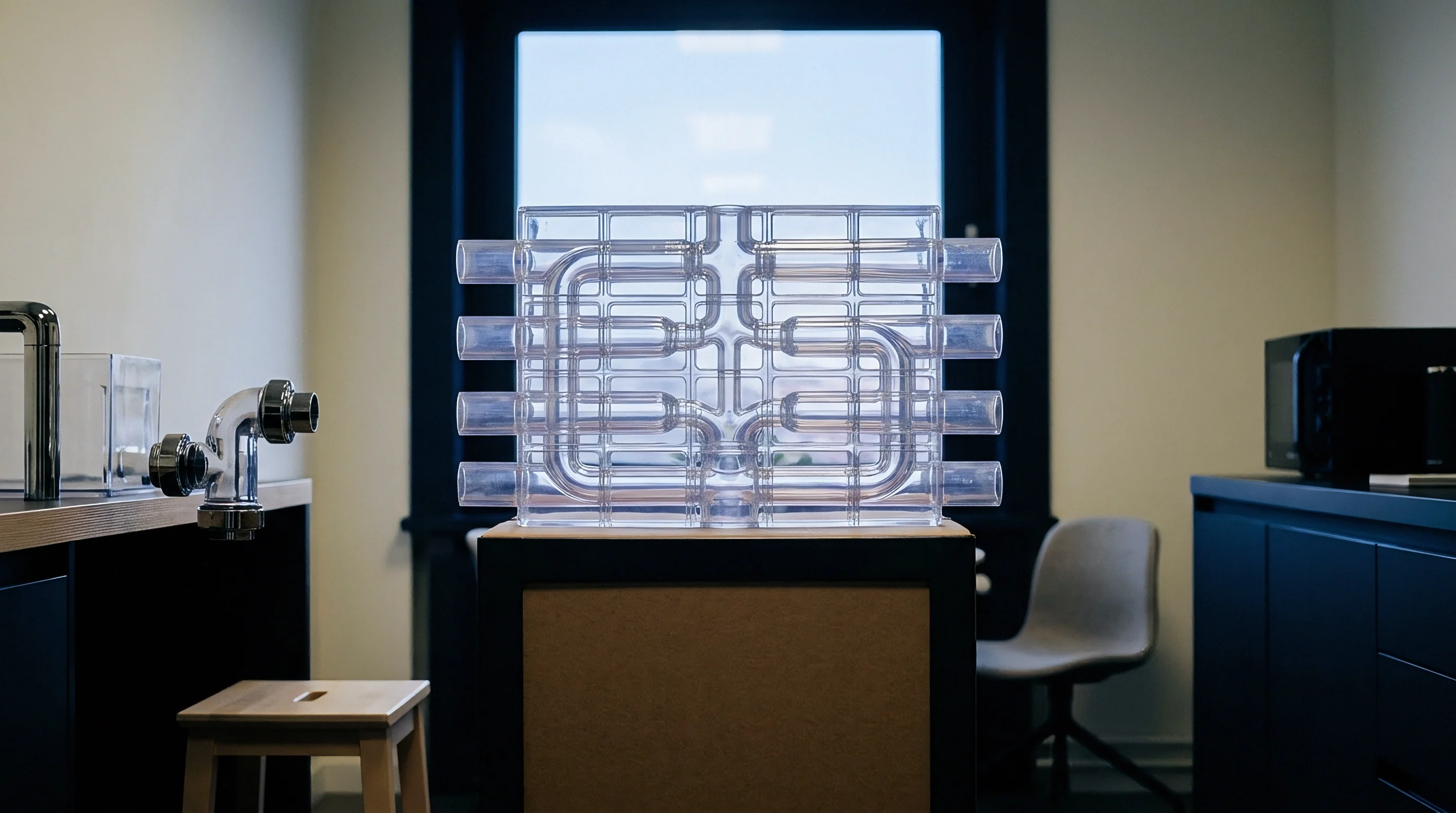
Three-dimensional melt repositioning addresses runner viscosity segregation by manipulating the spatial orientation of the laminar boundary layers. Passing the melt stream through an out-of-plane elevation change turns the flow axis 90 degrees prior to subsequent channel branching. Vertical elevation redirects the melt.
The hotter, low-viscosity boundary layer that resided along the runner wall now positions itself centrally across the downstream split plane, dividing evenly into both subsequent runner channels.
Executing an out-of-plane branch repositioning places the shear-induced thermal gradient symmetrical to the parting plane of the secondary runner. In an eight-cavity layout utilizing a primary sprue runner and secondary cross branches, the primary split deposits high-shear melt onto the inner sidewalls of the secondary channel. A 90-degree out-of-plane rotation flips these stratified layers onto the top and bottom surfaces of the tertiary channel.
Radial symmetry restores uniform flow. When the tertiary channel subsequently splits left and right to feed individual cavities, both cavity gates receive identical proportions of hot boundary melt and cold core melt.
Which Branching Levels Require Laminar Reorientation?
Manifold cavitation count dictates the specific runner intersections requiring three-dimensional rotation. An eight-cavity mold contains two branching levels: the primary split at the sprue and the secondary splits feeding cavity pairs. Incorporating melt rotation geometry at the secondary branching point balances all eight cavities.
A sixteen-cavity tool incorporates three branching levels, generating compound shear asymmetries where secondary splits impart new shear profiles onto already segregated laminar layers.
Cavity fill weight variations exceed twelve percent across an unrotated sixteen cavity cold runner operating at injection times below one second.
In thirty-two and sixty-four cavity molds, secondary and tertiary runner branches experience compounding velocity and shear shifts. Without progressive 3D rotations at each successive branch level, outer cavities experience severe freeze-off delays while inner positions pack to flashing. Implementing rotation at the secondary intersection addresses primary imbalance, whereas tertiary rotations eliminate localized imbalances within four-cavity sub-groups.
Arranging branch elevations so perimeter shear layers enter subsequent splits symmetrically neutralizes viscosity variation across cavities.
Steel
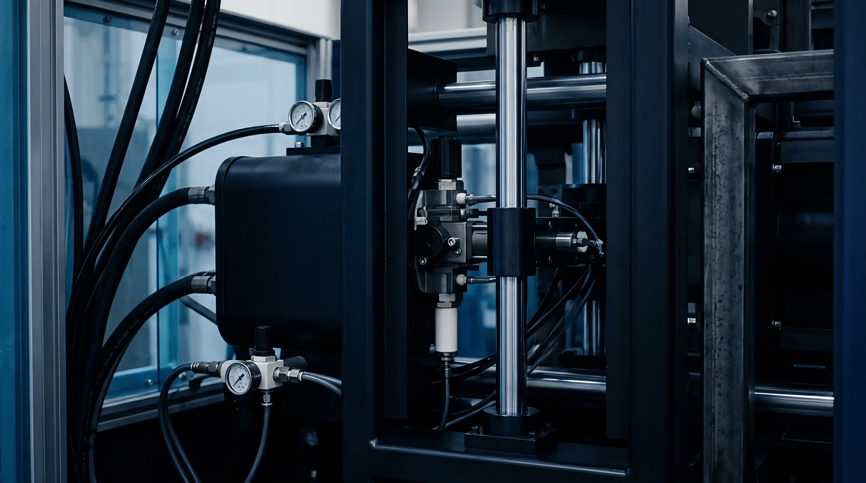
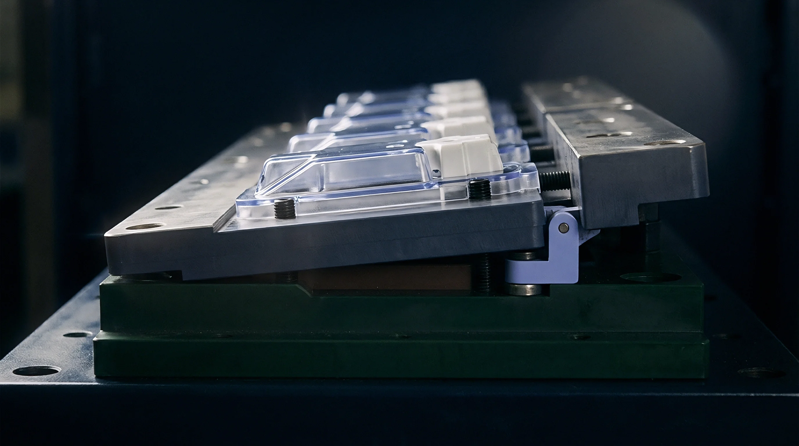
Cutting out-of-plane runner geometry into mold plates demands strict precision across parting line elevations and CNC toolpaths. Fabricating a rotated branch runner involves split-level runner plates or specialized insert assemblies where the melt channel transitions vertically between plates. Cutter deflections introduce channel steps.
A standard two-plate mold transitions into a three-plate runner system or receives stepped parting-line inserts machined to tolerances within ±0.010 mm.
Vertical runner drops require continuous draft to facilitate part and runner ejection without hangup. Draft angles on vertical transitional branches range between 5 and 10 degrees per side. Draft angles prevent runner hangup.
Channel cross-sections transition from parabolic or trapezoidal profiles into full round runners at the point of elevation change, maintaining a uniform hydraulic diameter to prevent localized stagnation or secondary shear spikes.
| Tool Steel Grade | Hardness (HRC) | Channel Tolerance (mm) | Draft Angle (deg) | Surface Finish (SPI) | Milling Method |
|---|---|---|---|---|---|
| 1.2344 / Premium H13 | 48 – 52 | ±0.008 | 7.0 | A-2 (Diamond 3 µm) | 5-Axis High Speed Ball Nose |
| 1.2083 / 420 Stainless | 50 – 54 | ±0.010 | 8.0 | A-3 (Diamond 6 µm) | CNC Sink EDM Form Tool |
| 1.2738 / P20+Ni | 30 – 34 | ±0.012 | 5.0 | B-1 (600 Grit Paper) | 3-Axis CNC Ball End Mill |
| 1.2379 / D2 Tool Steel | 58 – 60 | ±0.005 | 10.0 | A-2 (Diamond 3 µm) | Wire EDM with Sinker Form |
Polished surfaces reduce localized drag. Sinker EDM electrodes formed from copper-tungsten produce clean transitions along the Z-axis turn, eliminating cutter witness marks that disrupt laminar flow. Parting line mismatch between opposing mold halves along the rotated branch must not exceed 0.008 mm, as step defects create uncontrolled localized shear heating that counteracts the designed repositioning effect.
Tooling engineers evaluate multiple fabrication parameters during insert construction:
- Hydraulic Diameter Continuity across the vertical transition maintains steady melt velocity without pressure surges.
- Z-Level Step Alignment verified by coordinate measuring machines confirms elevation matching within 0.006 mm.
- Ejection Pin Placement located directly beneath runner branch turnouts prevents runner deformation during mold opening.
- Thermal Isolation Gaps surrounding runner insert pockets isolate localized runner plate heating from cavity cooling circuits.
Toolmakers frequently claim that thermal imbalances vanish once the mold reaches equilibrium temperature and that downstream gate adjustments provide identical results.
Balance
Press-side verification validates melt distribution across all cavitation branches through empirical measurement. Scientific molding methodologies isolate rheological flow behavior from machine pressure limits. Short shots isolate filling fronts.
Running progressive injection fill studies without hold pressure reveals the true mechanical filling order of the cavities.

Will Short Shots Expose Secondary Imbalance?
Injecting volumetric shots at 20, 40, 60, 80, and 95 percent fill exposes filling disparities across the tool layout. Tools with unrotated runner branches exhibit severe volumetric divergence at 80 percent fill, where inner cavities achieve complete fill while outer positions remain empty shells. Part weights track packing volume.
Incorporating 3D branch rotation compresses cavity-to-cavity weight variance at 95 percent fill down to less than 1.5 percent across the complete shot matrix.
Tool acceptance under DIN 16742 Group Four requires cavity-to-cavity dimensional tolerance capability indices to exceed 1.33 across thirty consecutive shots.
Cavity pressure sensors installed directly behind gate entries and at end-of-fill positions document dynamic packing variations. In an unbalanced sixteen-cavity mold, peak cavity pressures at the end of fill diverge by up to 28 MPa between inner and outer rows. Cavity transducers expose pressure deviations.
Implementing out-of-plane rotation aligns peak cavity pressures across all sixteen positions to within a 2.2 MPa band, eliminating flash and sink divergence.
| Cavity Position | Standard Fill Time (s) | Standard Part Mass (g) | Standard Peak Press (MPa) | Rotated Fill Time (s) | Rotated Part Mass (g) | Rotated Peak Press (MPa) |
|---|---|---|---|---|---|---|
| Cavities 1-4 (Inner Row) | 0.74 | 14.82 | 68.4 | 0.89 | 14.22 | 54.1 |
| Cavities 5-8 (Mid-Inner) | 0.82 | 14.45 | 61.2 | 0.90 | 14.20 | 53.8 |
| Cavities 9-12 (Mid-Outer) | 0.94 | 13.91 | 48.5 | 0.91 | 14.18 | 53.2 |
| Cavities 13-16 (Outer Row) | 1.12 | 13.18 | 40.1 | 0.91 | 14.15 | 52.7 |
| Data collected at 95 percent volumetric fill without hold pressure; machine injection speed set at 45 mm/s. | ||||||
Press technicians follow a systematic procedure to qualify rotated runner tools during site trials:
- Establish machine volumetric switchover by position, targeting an unfilled part at 95 percent of full part volume without pack pressure.
- Collect five consecutive short-shot sets and record individual part weights by cavity position on a 0.001 g resolution laboratory balance.
- Calculate the percentage filling balance by dividing the minimum cavity part weight by the maximum cavity part weight within each shot.
- Engage packing pressure incrementally to evaluate gate freeze times across all cavities using individual part mass determinations.
- Verify part critical dimensions under DIN 16742 across 32 consecutive cycles to validate process capability metrics.
Whether high thermal conductivity mold alloys eliminate the necessity of physical runner rotations in micro-molding applications remains an unsettled question among tooling specialists.
Recovery
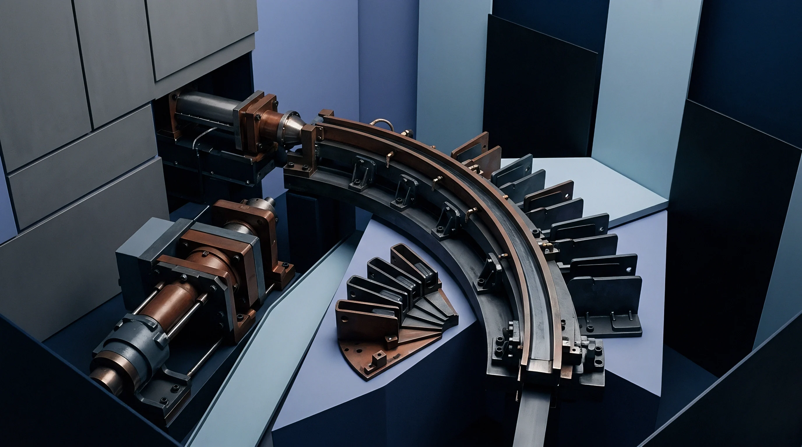
Capital deployed for engineered runner rotation inserts offsets piece-price penalties and machine downtime across production lifecycles. Modifying standard runner branches to incorporate 3D rotations adds between 3,500 and 12,000 USD to initial tooling build costs, depending on cavitation count and mold plate complexity. Tool modifications escalate production overhead.
Attempting to balance tools through empirical gate sizing introduces recurrent operational expenses that dwarf initial moldmaking investments.
Flow paths carrying boundary layers into opposing mold sectors cancel inherent shear imbalances.
Artificially restricted gates balance filling at only one specific injection velocity and melt viscosity. When batch-to-batch resin viscosity shifts by ±10 percent, artificially balanced molds de-synchronize immediately, generating rejected lots. Tooling changes generate unexpected overhead.
Rotated branch runners balance melt viscosity geometrically, maintaining uniform flow distribution across wide injection speed envelopes and resin lot variations without altering gate orifices.
Uniform packing limits scrap generation. Scrap rates on unrotated high-cavitation precision tools regularly hover between 4 and 9 percent due to dimensional spread and flash. Balancing the runner network through melt rotation reduces cavity scrap rates to under 0.6 percent, compressing machine cycle times by eliminating extended packing cycles needed to force material into starved outer cavities.
Gate adjustments mask rheological imbalance.
Inserting ISO 20457 tooling acceptance stipulations specifying maximum allowable cavity-to-cavity dimensional standard deviations shifts corrective machining costs onto the mold builder prior to final handover.