Quantifying Polymer Melt Erosion Rates across Hardened Tool Steels under High Glass Filler Loadings
Quantifying polymer melt erosion across tool steels requires balancing matrix shear rate and substrate carbide fraction to extend insert operational life.


Grit
When molten polymers filled with solid glass flow through runner channels at hydraulic pressures above one hundred megapascals, high-velocity rigid fibers suspended in the viscoelastic fluid continuously erode the channel surfaces. Solid glass fibers have a Mohs hardness of 5.5 to 6.5, well above the unhardened surface hardness of standard cavity steels. As the composite melt streams through narrow gates and geometric transitions, sharp fluid velocity gradients drive these rigid particles into repeated contact with boundary-layer walls.
The resulting mechanical wear on the mold steel depends on matrix viscosity, fiber volume fraction, and local shear rate.

Shear Stress and Fiber Orientation Dynamics
Near the cold mold wall, steep velocity gradients across the melt stream press hard filler particles against the polished surface. Shear-induced migration pushes glass fibers along specific streamlines, packing them tightly within the boundary layer. Polymer viscosity acts as a pressure medium that drives angular fiber ends into the metal substrate.
Because higher resin viscosity transfers greater normal force to the suspended glass, running glass-filled polyamides, polybutylene terephthalate, or polyphenylene sulfide at lower melt temperatures increases mechanical wall shear stress and accelerates substrate loss.
Gate erosion accelerates dramatically where the melt stream directly impacts cavity walls perpendicular to the primary flow direction.
Fiber geometry strongly dictates local wear patterns. Short glass fibers averaging 200 to 400 micrometers align quickly with flow streamlines in flat cavity sections, reducing normal impact forces and causing mostly shallow sliding abrasion. Long glass fiber compounds containing fibers up to 12 millimeters behave differently, tumbling, bending, and interlocking during injection.
Melt velocity profiles force these longer structural fibers to rotate within convergent gate channels, driving sharp fracture ends into the steel surface and elevating localized impact stress.

Micro Cutting and Micro Ploughing Mechanics
At impingement angles below thirty degrees, sharp glass fragments slice narrow channels into softened surface layers. This micro-cutting removes discrete microscopic ribbons of steel with every stroke. Micro-ploughing, by contrast, shoves metal to the sides of the abrasion track without immediately detaching it.
Cyclic thermal and mechanical stress work-hardens these displaced ridges until they eventually spall off from fatigue. Micro-ploughing predominates along low-angle runner sections, whereas direct micro-cutting concentrates at gate entrances where convergent flow boosts particulate impact energy.
Proper steel selection ultimately dictates tool survival.
| Polymer Matrix Type | Glass Loading Weight Fraction | Typical Shear Rate Range (s⁻¹) | Boundary Layer Shear Stress (MPa) | Dominant Substrate Wear Mechanism |
|---|---|---|---|---|
| PA66 | 30 Percent GF | 10,000 to 25,000 | 0.12 to 0.22 | Shallow Micro-Ploughing |
| PA66 | 50 Percent GF | 15,000 to 35,000 | 0.28 to 0.45 | Micro-Cutting and Micro-Spalling |
| PBT | 40 Percent GF | 8,000 to 20,000 | 0.18 to 0.31 | Micro-Ploughing with Fatigue Ridge Loss |
| PPS | 50 Percent GF | 12,000 to 30,000 | 0.32 to 0.52 | Severe Impact Micro-Cutting |
| PEEK | 30 Percent LGF | 5,000 to 18,000 | 0.25 to 0.41 | Rotational Fiber End Impingement |
Temperature gradients across the melt stream significantly alter boundary-layer fluid dynamics. During initial filling, a cold mold wall creates a thin skin of frozen polymer that shields the underlying steel from direct fiber gouging. High injection velocities, however, generate intense viscous dissipation heating inside the high-shear boundary layer.
This dissipation remelts the protective skin, exposing bare tool steel to high-velocity particle bombardment. Oversights regarding local velocity peaks at gate transitions result in premature tool wall cavitation, flash, and unexpected downtime during initial production ramps.

Metallurgy
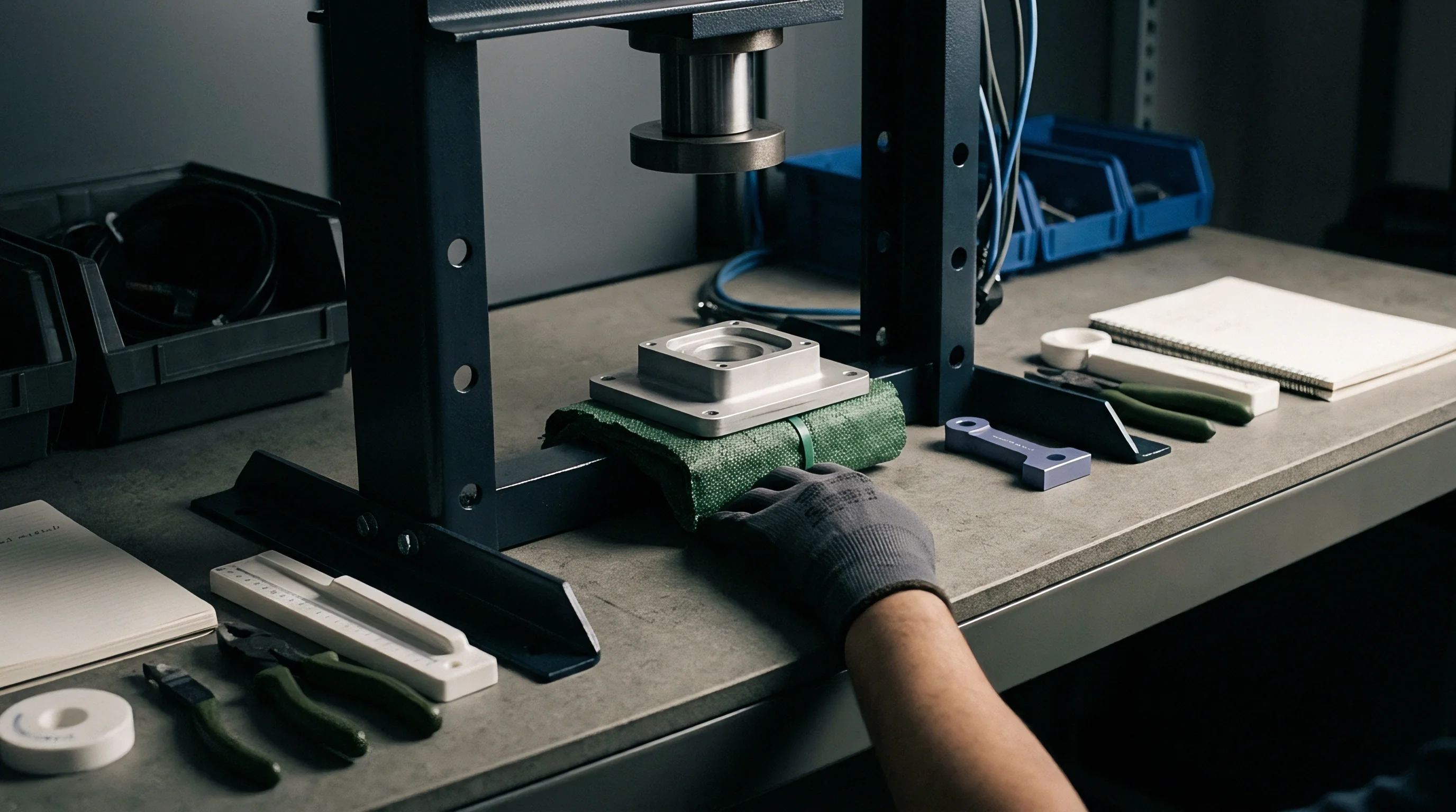
Selecting an alloy substrate for abrasive plastics requires evaluating both bulk yield strength and carbide dispersion. Standard tool steels rely on tempered martensitic matrices to resist gross plastic deformation under injection pressures up to two hundred megapascals. However, resistance to continuous micro-abrasion depends mostly on the volume fraction, hardness, and distribution of primary alloy carbides embedded in that matrix.
Iron matrix hardness alone will not prevent scratching when glass reinforcement particles equal or exceed its absolute hardness.

Tool Steel Microstructure and Hardness
Conventional pre-hardened P20 steel wears rapidly under continuous abrasive flow during long production runs. Supplied at 30 to 34 HRC, P20 lacks hard primary carbides and offers little resistance against forty percent glass-filled compounds. Standard AISI H13 vacuum heat-treated to 50 to 54 HRC delivers better core toughness and yield strength; its secondary chromium carbides provide reasonable protection against sliding wear in main cavity impressions, but wear down quickly when localized gate shear rates exceed twenty thousand inverse seconds.
Glass fibers effectively act as chisels against soft matrix phases.
High-carbon, high-chromium tool steels like AISI D2 reach working hardness levels of 58 to 62 HRC, where chromium-rich M7C3 primary carbides resist micro-ploughing much better than tempered martensite alone. However, the coarse, blocky carbides in conventionally cast D2 create local stress concentrations. Glass particles undercut the softer martensite pockets surrounding large carbide clusters, eventually dislodging entire carbide grains during extended runs.
Increasing substrate vanadium content to nine percent reduces gravimetric pin loss by sixty-four percent during high velocity PA66-GF50 injection trials.

Carbide Fraction and Coating Interfaces
High primary vanadium concentrations create hard obstacles that deflect angular reinforcement fragments. Powder metallurgy processing eliminates carbide segregation, producing an even dispersion of fine, spherical MC-type vanadium carbides measuring one to three micrometers. With absolute hardness values near 2800 HV, vanadium carbides far exceed the hardness of E-glass.
CPM 10V and Vanadis 4 Extra incorporate high vanadium carbide fractions within tough martensitic matrices hardened to 60 to 64 HRC, maintaining gate integrity over millions of cycles.
| Tool Steel Grade | Standard Heat Treatment Hardness (HRC) | Carbide Volume Fraction (Percent) | Dominant Carbide Type | Relative Abrasion Resistance Index (H13 Baseline = 1.0) |
|---|---|---|---|---|
| AISI P20 (1.2311) | 32 HRC | < 1.0 | Iron Carbides (Fe3C) | 0.25 |
| AISI H13 (1.2344) | 52 HRC | 2.5 | Chromium Carbides (Cr7C3) | 1.00 |
| AISI D2 (1.2379) | 60 HRC | 12.0 | Chromium Carbides (M7C3) | 3.10 |
| CPM 10V | 62 HRC | 17.5 | Vanadium Carbides (MC) | 8.50 |
| Vanadis 4 Extra | 60 HRC | 11.5 | Vanadium Carbides (MC) | 6.20 |
| CPM 15V | 64 HRC | 24.0 | Vanadium Carbides (MC) | 12.40 |
Physical vapor deposition coatings apply thin ceramic barrier layers over polished steel. Titanium nitride, chromium nitride, and titanium aluminum nitride coatings deposited at thicknesses of two to five micrometers deliver surface hardness above 2500 HV. Coating performance depends on substrate yield strength: if a softer substrate flexes under localized impact, the thin hard coating cracks and delaminates.
Combining powder metallurgy substrates with high-adhesion chromium nitride surface treatments yields optimal erosion resistance. Rapid gate recession often stems from unexpected filler breakage rather than inadequate carbide volume in the substrate.

Bench
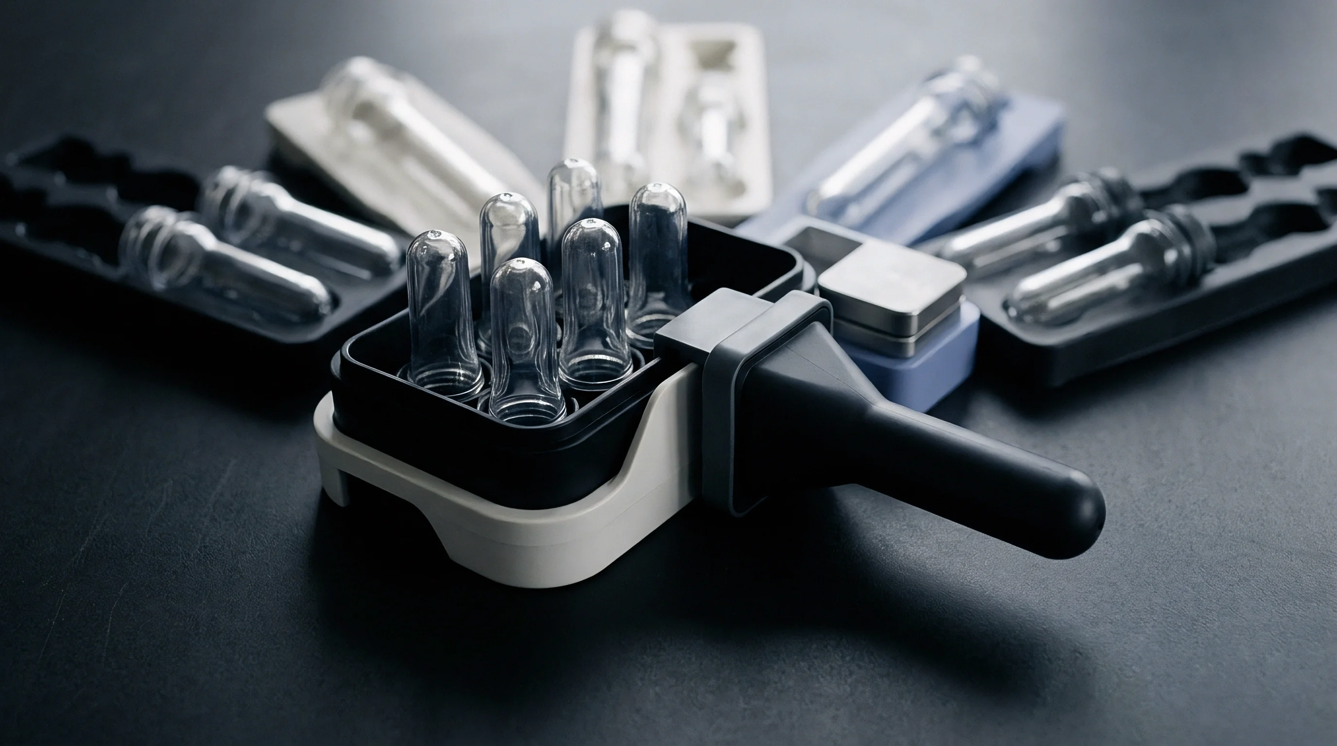
Accurately measuring steel removal under active molding conditions requires specialized laboratory test rigs operating at high pressures. Standard dry-sand rubber wheel testing per ASTM G65 measures ambient sliding abrasion but misses fluid shear stress and polymer melt temperatures. Similarly, gas-jet impact testing per ASTM G76 measures solid particle erosion without simulating the boundary-layer viscosity gradients inside injection cavities.
Meaningful wear data requires specialized slit-die inserts or instruments that process highly reinforced melts under controlled temperature and pressure.

Slit Die Gravimetric Testing Protocols
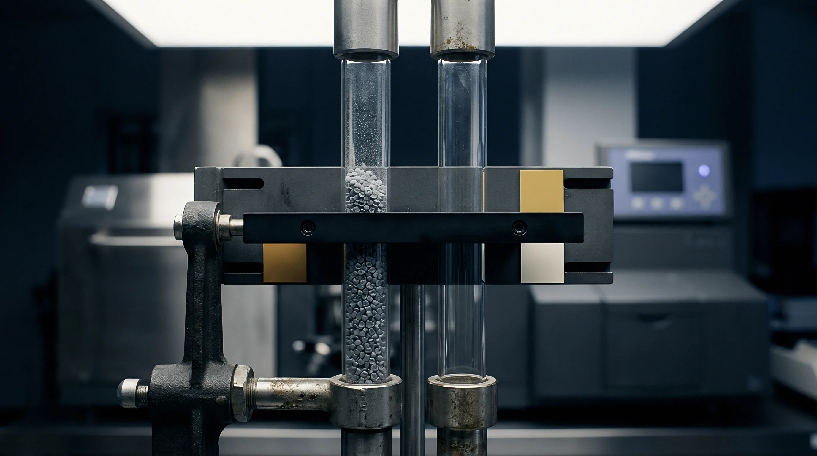
Extruding fifty percent glass-filled polyamide through removable capillary inserts isolates melt velocity from cavity geometry effects. Continuous extrusion rigs pump heated glass-filled polymer through precision-ground test slits for set durations. Micro-balances measure gravimetric loss down to one hundredth of a milligram after high-temperature vacuum pyrolysis removes residual polymer.
Combining mass loss with known alloy density gives precise volumetric erosion in cubic millimeters of steel lost per kilogram of extruded compound.
Slit die configurations effectively isolate key flow variables during testing.
Mass loss data must be paired with the structural failure modes observed on the production floor:
- Gate Land Recession expands effective gate area, dropping cavity pressure and causing part sink marks or incomplete filling.
- Runner Impingement Pitting creates localized undercut pockets that trap degraded polymer and impede automatic runner ejection.
- Vent Cavitation Erosion enlarges gas escape channels, resulting in excessive parting line flash and plastic burn marks.
- Core Pin Thinning reduces structural cross sections under high hydraulic pressure, causing deflection and wall thickness variation.
Adopting DIN 16742 tolerance group TG3 forces replacement of gate inserts once linear land recession exceeds twenty micrometers.
Surface Profilometry and Isotope Tracing
Non-contact optical sensors map surface depth changes across target areas down to sub-micron resolution. White light interferometry and focus variation microscopy construct 3D surface topologies of eroded inserts, while ISO 25178 optical areal parameters track the transition from ground surface lay to deep erosion grooves. Comparing areal roughness across intervals quantifies micro-ploughing displacement before net steel loss takes place.
| Measurement Technique | Primary Measurement Output | Minimum Detection Limit | Primary Operational Limitation |
|---|---|---|---|
| Gravimetric Mass Loss | Total Sample Weight Difference (mg) | 0.01 mg | Requires complete polymer cleanoff without substrate destruction |
| White Light Interferometry | 3D Areal Surface Topology (µm) | 0.05 µm | Line of sight optical access required across target geometries |
| Thin Layer Activation | Gamma Ray Intensity Decay (kBq) | 0.01 µm depth equivalent | Demands specialized radioactive isotope handling approvals |
| Differential Pressure Loss | Slit Flow Hydraulic Delta P (bar) | 0.10 bar | Indirect indicator influenced by melt viscosity variations |
Radioactive tracer techniques allow real-time wear measurement during continuous injection molding. Cyclotron bombardment irradiates a precise surface layer on test inserts, converting atomic nuclei into Cobalt-56 or Cobalt-57 radioisotopes. Gamma-ray spectrometers then detect minute radioactive particles swept away in the solidified plastic melt stream.
Decay curves calculate linear wall recession continuously without disassembling the mold. Including ISO 20753 wear testing compliance in tooling purchase agreements assigns financial responsibility for premature cavity erosion to the tool builder.


Kinematics
Relating material loss to fluid transport requires extending classic tribological equations into non-Newtonian fluid dynamics. Standard Archard wear calculations for dry contact assume linear relationships between wear volume, normal load, and sliding distance. Modeling polymer melt erosion requires accounting for melt viscosity, filler volume fraction, shear-rate power-law exponents, and local impact angles to capture the transition from fluid-lubricated shear wear to direct particulate impact.

Modified Archard Wear Equations for Non Newtonian Melts
Traditional linear sliding equations fall short because fluid viscosity alters the normal forces exerted against channel boundaries. Incorporating local wall shear stress accounts for polymer hydrodynamic support. Under this model, volumetric steel removal scales nonlinearly with melt velocity, expressing loss as filler concentration raised to an empirical loading exponent multiplied by melt velocity raised to exponents between 1.8 and 2.6.
Erosion rates scale nonlinearly with flow velocity.
Consider a four-cavity tool running polyamide 66 with fifty percent short glass fiber filler at a melt temperature of 290°C and an injection rate of 45 cubic centimeters per second through H13 gate inserts hardened to 52 HRC. Operating conditions produce a gate shear rate of 28,000 inverse seconds and localized normal contact stress of 18 MPa. Under these steady-state conditions, volumetric wear across the gate land averages 0.042 cubic millimeters per 100,000 cycles, causing 14 micrometers of linear gate land recession.
Upgrading the gate inserts to CPM 10V powder metallurgy steel at 62 HRC under identical process conditions drops the wear rate to 0.009 cubic millimeters per 100,000 cycles and recession to 3 micrometers. This material change extends insert operational life from 140,000 cycles to over 650,000 cycles before gate dimensions drift out of tolerance.
Doubling melt injection velocity quadruples volumetric steel loss across hardened H13 gate boundaries.

Velocity Power Law Exponents across Injection Speeds
Increasing flow rate elevates wall shear stress nonlinearly, accelerating wear beyond simple volumetric scaling. Faster injection speeds reduce cooling inside runner channels, raising local surface temperatures and lowering melt viscosity. Lower viscosity lets glass fibers rotate more freely, raising the likelihood of sharp end-on particle impingement against gate land boundaries and driving up wall loss.
- Melt Temperature Calibration lowers polymer viscosity, reducing normal forces exerted by rigid filler particles against cavity walls.
- Injection Velocity Profiling decelerates the melt front through narrow gate passages to minimize impact energy at wall contact zones.
- Cavity Pressure Monitoring identifies localized pressure drops indicating progressive gate land expansion across consecutive shifts.
- Gate Substrate Inspection verifies physical dimensions against CAD models every fifty thousand shots during high-volume production runs.
Cavity pressure drops as soon as gate land recession occurs. How melt elasticity and wall slip alter localized particle friction coefficients under non-isothermal flow remains an active area of research in processing laboratories.

Refurbishment
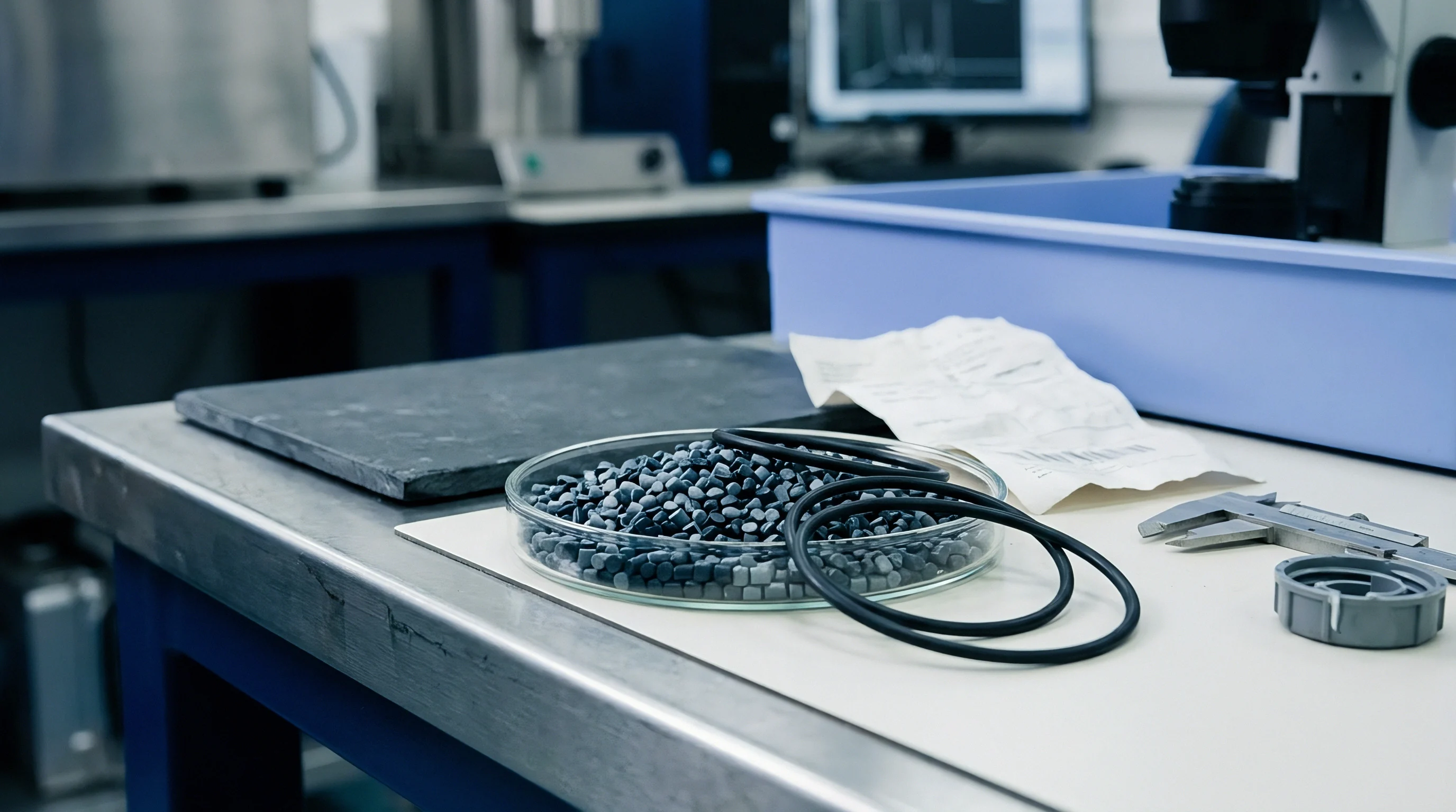
Tooling exposed to fifty percent glass reinforcement requires structured maintenance cycles to avoid irreversible parting line damage. Progressive gate wear enlarges the fill cross-section, dropping local injection pressure and disrupting cavity filling balance. Left unchecked, gate recession causes flash, venting failures, and dimensional non-conformance.
Scheduled tool refurbishment protects primary mold bases while holding strict part tolerances.

Modular Insert Strategies and Maintenance Cycles
Isolating high-velocity flow regions inside small, replaceable sub-assemblies keeps maintenance costs manageable. Gate lands, runner intersections, and sprue puller pins wear up to ten times faster than main cavity surfaces. Building these regions as modular inserts lets technicians swap worn components without remachining primary cavity blocks.
Precision-ground locating pockets and wire EDM paths allow quick insert replacement right on the press.
Unmaintained parting lines flash rapidly under pressure.
Modular designs make it economical to use premium powder metallurgy steels strictly where needed. Building entire cavity blocks from CPM 10V or Vanadis 4 Extra creates prohibitive material and machining costs. Using standard AISI H13 for main mold plates alongside CPM 10V inserts at gate entries balances tool longevity against upfront cost.

Amortization Impact on High Volume Tooling Budgets
Part pricing formulas must account for early steel replacement intervals when molding abrasive compounds. For example, a tool producing automotive connectors from fifty percent glass-reinforced polybutylene terephthalate requires new gate inserts every 250,000 cycles. Factoring insert fabrication, spare inventory, and press downtime into unit amortization protects profit margins over multi-year programs.
Tooling design choices ultimately dictate long-term maintenance expenditure.
Specifying replaceable powder metallurgy gate inserts before machining cavity blocks prevents costly tool overhauls when running highly reinforced compounds.