In Situ Coherence Scanning Interferometry Calibration for Deep Draft Hardened Steel Cavity Sidewalls
In situ CSI calibration for deep draft cavity sidewalls requires right-angle fold mirror optical path matching and verified local step height standards.


Access
Positioning an optical head inside a 150 mm deep tooling cavity with draft angles below 1.5 degrees is a strict physical challenge. Standard coherence scanning interferometry objectives provide working distances of just 0.5 mm to 10 mm. Once cavity clearance drops below 30 mm, fitting a conventional vertical optical barrel into the slot becomes impossible.
Hardened tool steel cavity blocks (such as 1.2343 or H13 at 52 to 58 HRC) still require precise sidewall profile measurements to verify draw lines, spark-erosion micro-textures, and diamond-polished finishes before the tool can be released for production.
Reaching into deep recesses relies on long working distance relay optics paired with right-angle fold mirrors or specialized slender-tube Linnik interferometers. Mounting a right-angle mirror to the tip of a Mirau objective turns the optical axis by 90 degrees, aiming the measurement beam straight at the vertical cavity wall. But that mechanical extension brings a clear optical trade-off: lengthening the clear optical path lowers the system’s effective numerical aperture, which narrows the maximum surface slope angle the instrument can measure before losing reflected light.
High aspect ratios quickly narrow objective choices because geometry dictates light collection. Clearance calculations for narrow cavities must account for the outer diameter of the objective casing, the fold mirror housing, and the tilt clearance needed to avoid hitting opposing walls. A cavity measuring 20 mm wide by 100 mm deep sets a tight spatial envelope for the optical probe.
| Optical Configuration | Working Distance (mm) | Max Cavity Aspect Ratio | Max Measurable Slope (deg) | Numerical Aperture |
|---|---|---|---|---|
| Standard Mirau (10x) | 7.4 | 1:1 | 14.0 | 0.30 |
| Long Working Distance Mirau (20x) | 19.0 | 3:1 | 11.5 | 0.25 |
| Right-Angle Fold Mirror Attachment (10x) | 4.5 | 8:1 | 7.2 | 0.15 |
| Slender Linnik Remote Probe (5x) | 42.0 | 12:1 | 5.0 | 0.10 |
Designing the probe interface requires careful mechanical clearance modeling. The probe shaft must enter the cavity without flexing, as even micro-radian deflections induce visible wavefront tilt across the field of view. Shaft stability sets baseline measurement repeatability, making materials with high specific stiffness ~ such as solid tungsten carbide or carbon-fiber composites ~ essential to prevent static sagging during horizontal insertion.
The optical quality of the relay mirror directly governs wavefront aberration levels. Standard front-surface aluminum mirrors introduce phase shifts and polarization changes across the aperture that degrade white-light fringe contrast. Using high-reflectance dielectric coatings tuned to the light source wavelength (typically centered between 520 nm and 630 nm) keeps fringe visibility above 0.4 across the central 80 percent of the field of view.
Aligning the fold mirror inside the objective mount requires sub-micron tolerances, as mounting angular errors produce spatial astigmatism that shifts the zero-path-difference fringe location relative to the mechanical focal plane.
Lowering an oversized optical assembly into a tight cavity slot risks physical contact with polished steel. A collision can destroy the optical probe, deeply scratch hardened cavity inserts, and derail bring-up schedules across multi-cavity injection mold programs.

Fringe
Getting a reliable interferometric signal from hardened tool steel relies on capturing localized spatial coherence peaks within a narrow optical window. Coherence scanning interferometry determines surface height by moving an optical objective vertically while tracking light intensity changes across a sensor array. The white-light source creates an interference envelope whose peak corresponds to zero optical path difference between the reference arm and sample surface.
On steep sidewalls, back-scattered light gets deflected past the objective aperture.
Hardened steels like 1.2083 stainless and 1.2343 tool steel have complex refractive indices where both the real index and the extinction coefficient govern phase change on reflection. That phase change shifts the apparent optical position of the surface relative to its physical boundary. While uniform on flat surfaces, local slope variations from electrical discharge machining or abrasive polishing cause localized phase shifts on deep draft sidewalls.
These shifts corrupt phase reconstruction algorithms, introducing height errors between 12 nm and 85 nm on ground steel surfaces.
Hardened tool steel with surface tilt exceeding 4.2 degrees reduces reflected light intensity below signal threshold on a 0.3 numerical aperture lens.
Steeper draft angles reduce the back-scattered photon flux reaching the detector. When local slope exceeds half the angular aperture of the objective lens, specular reflection misses the entrance pupil completely. Signal acquisition then depends entirely on weak diffuse scattering from micro-roughness features.
If the surface has a mirror finish (SPI A1 or A2 polish with Sa below 10 nm), diffuse scattering falls to zero, causing complete signal loss across vertical sidewalls.
- Specular Beam Misdirection happens when local sidewall tilt sends reflected wavefronts outside the objective entrance pupil, causing total signal dropout.
- Phase Change Discontinuity arises from microstructural variations across tool steel phase boundaries, shifting local fringe phase relative to the coherence envelope peak.
- Envelope Peak Skewing results from asymmetric light collection across high-aspect aperture stops, biasing height readings toward the lower edge of the optical cone.
- Ghost Interference Reflections stem from internal reflections off secondary surfaces inside narrow fold-mirror housings, superimposing false fringe packets onto sample data.
Aperture synthesis techniques and controlled stage tilt help compensate for these slope limits. Tilting the optical head or the cavity insert to align the illumination axis perpendicular to the draft angle brings specular reflection back along the primary optical path. This realignment restores fringe modulation depth from near-zero up to 0.65, allowing accurate height mapping during white-light scans.
Modulating illumination intensity during scanning prevents detector saturation on bright flat lands while maintaining adequate signal-to-noise ratios on inclined sidewall zones.
Signal processing algorithms extract surface topography by combining fringe envelope peak evaluation with the underlying optical phase. Low signal-to-noise ratios on steep sidewalls lead to fringe order identification errors, commonly called phase jumps. A single fringe order mistake introduces a height jump equal to half the mean illumination wavelength (roughly 260 nm for green LED sources).
Standard processing algorithms use spatial neighbor filtering and envelope-phase consistency checks to filter out unmodulated pixels before generating final surface topography profiles under ISO 25178-2 standards.
Equipment vendors frequently attribute signal dropouts to poor toolroom surface preparation, ignoring the numerical aperture limits inherent to their long-working-distance optics.

Standard
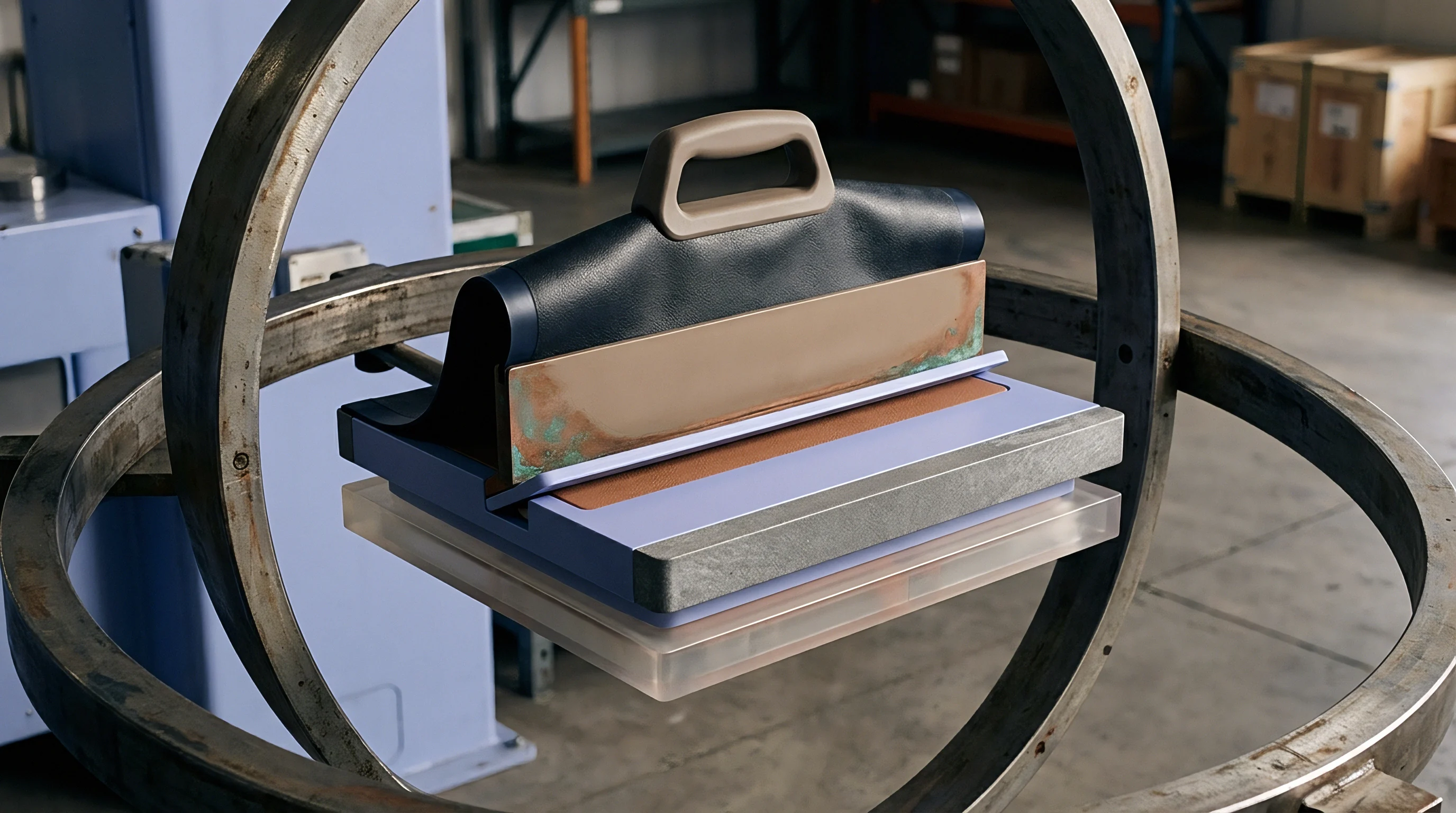
Calibrating coherence scanning instruments inside narrow tool recesses demands reference artifacts that reproduce identical optical path geometries. Standard flat calibration targets checked on open optical benches ignore the wavefront distortion, signal attenuation, and mechanical vignetting introduced by right-angle fold mirrors and long relay extensions. A dedicated calibration block for deep cavity metrology must integrate step heights, lateral pitch grids, and known slope features directly into a compact body designed for insertion into narrow tool slots.
Deep Draft Calibration Artifact Design
Calibration standards meant for cavity insertion use low-thermal-expansion substrates such as clear fused silica or Zerodur. Step heights range from 100 nm for optical phase verification up to 50 µm for checking z-axis scanner linearity. Etched lines or evaporated chrome patterns on the surface form lateral grids with pitch dimensions certified to within 0.05 µm traceability to national metrology institutes.
Thermal stability of the artifact assembly is critical during in-situ shop floor testing, where machine beds and cavity blocks regularly experience temperature swings between 18 °C and 28 °C. Mounting Zerodur or fused silica components directly inside rigid steel frames causes stress-induced deformation from mismatched thermal expansion. Spring-loaded kinematic mounts absorb expansion differentials between the steel housing and low-expansion glass, keeping target flatness within 15 nm across the working surface.

Step Height and Lateral Transfer Verification
Calibration accuracy depends on maintaining constant optical path length matching between the interferometer’s internal reference arm and the sample path through the long relay probe. Any thermal drift in probe housing dimensions alters this balance, causing fringe contrast loss and z-scale amplification errors on mold inserts.
ISO 25178-701 section 5.3 mandates calibration of optical instrument z-scaling using step height standards measured under identical optical path length configurations.
Field verification of optical profiling instruments requires a deliberate operational sequence to isolate detector electronics noise from optical path distortions.
- Mount the deep-cavity calibration artifact securely inside the cavity slot using kinematic locate pins to ensure repeatable spatial alignment.
- Position the right-angle interferometric probe at the target measuring depth, maintaining at least 1.5 mm mechanical clearance from opposing cavity walls.
- Run a light intensity normalization routine across the field of view to balance throughput variations caused by mirror coatings and aperture restrictions.
- Perform a ten-trace vertical scan over a certified 10 µm step height target, calculating mean step response and the z-axis scale linearity factor.
- Measure a lateral grid target to quantify spatial distortion across horizontal and vertical axes induced by fold mirror optical tilt.

How Does Cavity Depth Degrade Artifact Traceability?
Deeper probe insertion increases both structural cantilever deflections and optical beam path turbulence. Air density variations within deep, narrow steel slots create localized refractive index gradients that cause subtle path length fluctuations, corrupting temporal phase shifting measurements. Traceability protocols require environmental stabilization periods where the tool block and optical assembly rest in thermal equilibrium for at least two hours before executing final calibration routines.
Calibration records must document ambient temperature, relative humidity, optical head serial number, fold mirror attachment identifier, and the specific z-calibration factor applied during signal reconstruction. According to ISO 25178-701 requirements, optical profiling instruments operating with non-standard relay optics without localized deep-cavity step height calibration forfeit metrological traceability for all surface roughness parameters reported on vertical or inclined geometries.

Vibration
Shop floor mechanical oscillations disrupt the optical path length scan during white-light interference peak detection. Sub-micron vertical movements between the optical objective and the steel cavity wall cause fringe phase jitter. When vertical displacement amplitude exceeds 20 nm during a single camera frame exposure, interference fringe contrast degrades significantly.
Mechanical noise distorts the coherence envelope, generating artificial surface roughness metrics and false height steps on smooth ground cavity walls.
Machine-integrated optical inspection head mounts encounter excitation frequencies from adjacent CNC machining centers, overhead crane operations, and press hydraulic pumps. Vibration spectra on toolroom shop floors typically concentrate energy between 10 Hz and 150 Hz. Low-frequency oscillations (below 30 Hz) induce rigid-body translational motion between the probe arm and the cavity wall, while higher frequency noise excites internal flexural modes within long slender optical probe extensions.
| Mitigation Technique | Isolation Bandwidth (Hz) | RMS Phase Error Impact (nm) | Rigidity Rating | Relative Integration Cost |
|---|---|---|---|---|
| Passive Elastomeric Isolators | > 45 | 18.5 | Low | 1.0x |
| Active Pneumatic Isolation Table | 1.5 – 200 | 1.2 | Medium | 3.5x |
| High-Speed Single-Frame Spatial Carrier | N/A (Optical) | 3.8 | High | 2.2x |
| Piezo-Actuated Active Path Length Control | 10 – 500 | 0.7 | High | 5.0x |
Integrating active pneumatic vibration isolation platforms under the cavity positioning stage attenuates floor excitation before it reaches the optical path. Active systems use feedback accelerometers and pneumatic actuators to suppress low-frequency disturbances, holding relative position stability between probe and sample within 2 nm RMS. Portable in-situ setups lacking active isolation tables rely on rigid mechanical clamping bridges that lock the optical objective directly to the cavity block housing during scan operations.
Vibration degrades optical coherence rapidly. High-speed camera sensors mitigate ambient vibration effects by capturing fringe patterns at acquisition rates exceeding 1,000 frames per second. High frame rates ensure that vertical step movements between consecutive frames remain below 5 nm, well within the sampling threshold of temporal phase-unwrapping algorithms.
Spatial carrier interferometry provides an alternative approach by extracting three-dimensional surface height data from a single camera frame, eliminating sensitivity to temporal phase noise entirely at the expense of lateral spatial resolution.
Ambient shop floor mechanical noise must remain below one quarter of the optical wavelength to prevent coherence peak blurring during single-pass temporal scanning.
Piezoelectric reference mirror compensation provides dynamic phase stabilization in high-vibration toolroom environments. Auxiliary optical sensor channels track reference interference fringes from a static region of the cavity block, feeding high-frequency displacement signals into a closed-loop piezo actuator attached to the internal reference mirror. The mirror shifts in real time to match mechanical jitter, freezing relative fringe motion across the primary measurement detector array.
Vibration control relies on rigid mechanical coupling rather than compliance; flexible damping elements between instrument optical heads and heavy steel cavity blocks introduce low-frequency resonance modes that worsen measurement uncertainty.

Kinematics
Multi-axis motion systems driving an optical probe into deep recesses introduce geometric runout and Abbe angular errors. When measuring deep cavity sidewalls, the positioning assembly must traverse vertical distances up to 150 mm while maintaining precise optical focus. Angular deviation in linear guide stages creates lateral position errors proportional to the offset distance between the axis guide rail and the optical focal point.
An angular pitch error of 10 arcseconds on a linear stage holding a 200 mm probe extension produces a lateral focal point displacement of nearly 10 µm.
Aligning the optical axis perpendicular to draft-angled sidewalls requires multi-axis goniometer stages or 5-axis articulated positioning heads. Cavity draft angles typically range from 0.5 degrees to 3.0 degrees. Measuring these surfaces without angular compensation reduces collected light intensity below operational limits.
Tilting the optical probe to mirror the draft angle restores normal beam incidence, preserving signal quality across deep vertical traces.
Positioning error stackups dictate total measurement spatial uncertainty inside deep cavities. Consider a 120 mm deep mold cavity measured using a 5-axis positioning system. Mechanical guide runout contributes 3.5 µm of pitch-induced offset.
Thermal expansion of the carbon-fiber probe arm under a 3 °C temperature change adds 1.8 µm of axial drift. Rotary bearing runout in the tilt axis adds 2.2 µm of radial displacement. The combined root-sum-square positional uncertainty reaches 4.5 µm at the bottom of the cavity recess.
Automated sidewall stitching operations must account for kinematic runout. Field of view limits on high-magnification objectives (typically 0.5 mm to 1.5 mm wide) require spatial stitching to profile tall vertical cavity walls. Software stitching algorithms align adjacent measurement tiles based on mechanical stage encoder coordinates or spatial feature matching.
Cumulative stage positioning errors cause boundary mismatches between stitched tiles, manifesting as artificial steps or slope discontinuities in the reconstructed full-depth cavity profile.
- Abbe Offset Amplification converts small angular guide errors into large spatial displacements at the tip of long optical probes.
- Thermal Shaft Expansion shifts the vertical distance between the stage position encoder and the optical focal plane during extended scan sequences.
- Rotary Bearing Tilt Drift introduces wobble in the probe rotation axis, causing optical field rotation across multi-angle cavity inspections.
- Stitching Boundary Discontinuity occurs when stage positioning errors exceed spatial overlap tolerances, distorting global cavity draft angle calculations.
High-precision optical setups utilize optical linear encoders mounted directly along the probe centerline to eliminate Abbe offsets. Closed-loop capacitive sensors mounted between the probe tip and the cavity steel provide real-time distance tracking, compensating for thermal expansion and mechanical structural sag before data processing begins.
How can toolmakers separate physical cavity sidewall waviness from kinematic stage trajectory errors when stitching twenty optical fields down a 150 mm deep hardened steel slot?

Dispute
Commercial friction between toolmakers and moulding buyers emerges when optical topography measurements fail to correlate with physical part ejection forces. A toolmaker presents coherence scanning interferometry data proving a cavity sidewall meets specified surface roughness metrics (Sa 0.10 µm, SPI A2 finish). The moulder takes delivery of the hardened tool steel core block, runs production trials with glass-filled polycarbonate, and experiences severe part sticking, pin push-through, and sidewall scoring.
The discrepancy traces back to optical instrument calibration failures on high-angle draft slopes.
Uncalibrated optical profilometers frequently underestimate surface roughness on steep sidewalls due to spatial frequency filtering inherent to low-NA long-working-distance lenses. High-frequency micro-roughness features (such as fine grinding marks or cutter chatter lines) scatter light outside the lens aperture, causing the optical instrument to smooth the measured surface topography artificially. The instrument reports an acceptable surface roughness value, while the physical steel cavity retains sharp asperities that lock into cooling plastic melt during injection pressure holding phases.
| Evaluation Metric | In-Situ Deep-Cavity CSI | Offline Stylus Profilometry | Offline Benchtop CSI | Machine-Mounted CMM Optical Head |
|---|---|---|---|---|
| Measurement Setup Time (min) | 25 | 45 (Requires Tool Teardown) | 60 (Requires Tool Cutting) | 15 |
| Vertical Depth Limit (mm) | 150 | 30 | 10 | 80 |
| Traceable Height Error (nm) | 12 | 50 | 2 | 35 |
| Capital Expenditure (€) | 145,000 | 18,000 | 110,000 | 85,000 |
| Risk of Tool Damage | Low | High (Contact Drag) | Destructive | Medium |
Contact stylus profilometers offer a historical baseline for surface roughness sign-off, but physical stylus tips cannot reach into narrow, deep cavity slots without specialized diamond probes on long, fragile shanks. Dragging a diamond stylus tip across high-polish H13 cavity inserts risks scratching optical-quality steel surfaces, creating permanent molding flaws that cost thousands of euros to repair. Optical metrology eliminates physical contact damage, but requires explicit agreement between buyer and moulder regarding optical filter settings, spatial bandwidth limits, and slope cut-off parameters under ISO 25178 standards.
Tooling procurement contracts must define measurement conditions explicitly to prevent sign-off disputes. Clear contract specifications rely on verified optical measurement procedures. A robust contract line specifies instrument type, objective magnification, numerical aperture, right-angle fold mirror calibration status, lateral pixel spacing, S-filter and L-filter cut-off values, and surface slope handling settings.
Specifying a surface roughness value of “Sa 0.08 µm” without defining optical measurement parameters leaves the tooling contract commercially unenforceable during quality disputes.
Uncalibrated optical sidewall profile data creates commercial deadlock when cavity surface measurements fail to match physical wear samples from ejection trials.
Amortization calculations for optical metrology equipment must account for avoided tool bring-up delays and reduced scrap rates. Deploying an in-situ deep-cavity interferometry system avoids removing heavy cavity inserts (often weighing over 500 kg) from machine bases for inspection on offline CMMs. Saving three days of tool teardown, transport, offline measurement, and re-alignment per modification loop recovers a €145,000 equipment investment across five complex multi-cavity tooling projects.
Quality assurance dossiers containing fully calibrated optical profile records provide indisputable proof of tool steel conformity before shipment across international borders.
Disputing parties must resolve surface parameter differences by performing comparative measurements on certified step height standards mounted inside equivalent physical cavity slots before declaring cavity non-conformance. Tooling buyers who accept cavity steel surface metrics without verified local step-height calibration assume full financial liability for post-delivery ejection failures and mold redesign costs.