Cross-Facility Metrology Calibration Protocols for Secondary Ultrasonic Assembly Fixtures
Standardizing cross-facility metrology on ultrasonic fixtures demands kinematic datum registration, thermal artifact scaling, and dynamic trigger force validation.

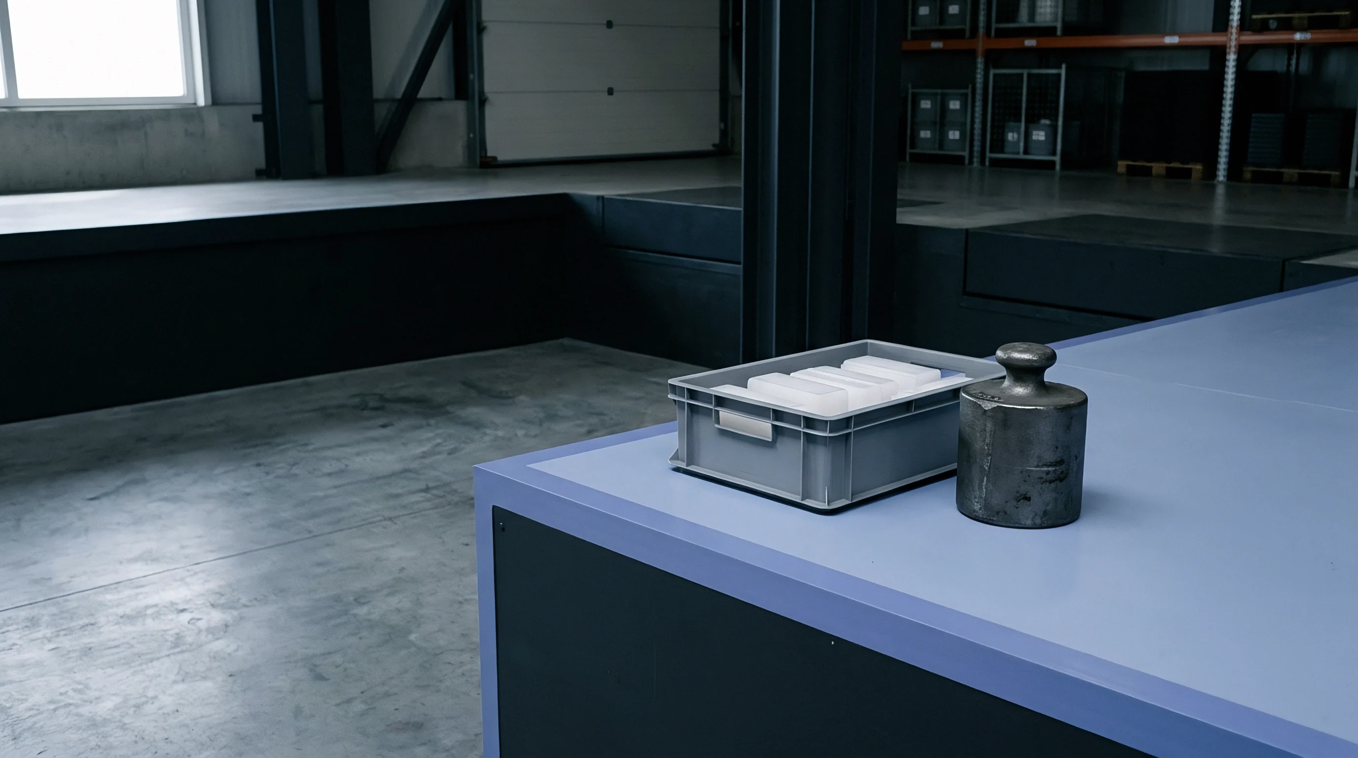
Datum
Primary locating points on secondary ultrasonic assembly fixtures establish the spatial alignment needed to focus high-frequency acoustic energy into a localized polymer melt. As molded thermoplastic components move from an injection press to a secondary assembly cell, dimensional variations creep in from cavity cooling, material shrinkage, and shop-floor conditions. The fixture holds these parts directly beneath an ultrasonic horn vibrating at twenty or forty kilohertz.
If the mechanical interface between part and nest yields under load, acoustic energy bleeds into the tooling rather than the joint. Maintaining a consistent reference frame across multiple plants requires a kinematic datum strategy that resists shipping strain and operator shifts.
Kinematic registration builds on classic six-point location theory: three primary points set the plane, two secondary points establish the alignment line, and a tertiary point locks the final axial degree of freedom. In single-site operations, toolmakers frequently cut full contoured nests that cradle the outer skin of the plastic housing. That full support distributes mechanical loads during welding, but it complicates cross-facility metrology.
Without discrete spherical contact pins, inspection teams rely on surface best-fit algorithms that conceal localized pocket wear, thermal distortion, and clamping deflections.
A 15-micrometer axial deflection at the primary locating pin under a 450 N pneumatic trigger force shifts the joint weld area by 0.12 square millimeters in 20 kHz assembly.
Steel expands predictably as temperatures rise. When a fixture calibrated at a central engineering center in Central Europe ships to a plant in Southeast Asia, ambient shop-floor shifts alter the spacing between locating points. A tool steel baseplate with four hundred millimeters between primary locating pins moves nearly forty micrometers across a ten-degree Celsius thermal shift.
If the receiving facility runs coordinate measuring machines without dynamic thermal compensation, the fixture appears out of spec. Local technicians often attempt to fix this by grinding locating pins or shimming reference blocks, destroying the baseline geometry established by the original toolmaker.
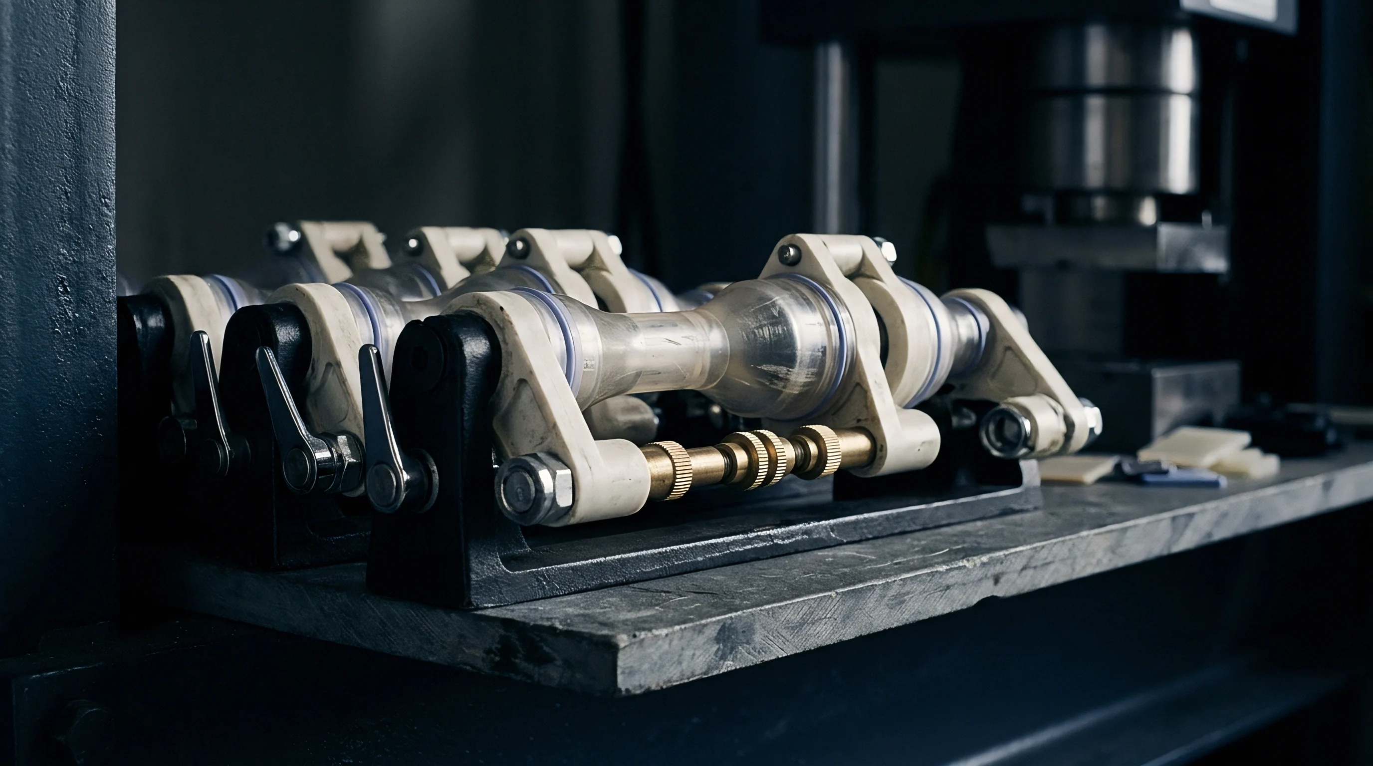
Kinematic Registration Mechanics
Contacts between locating pins and molded housings require specific geometric profiles to prevent localized plastic deformation. Spherical carbide contacts or hardened tool steel hemisphere pins provide point contact against flat reference pads molded into the part, minimizing contact area while keeping the component stable. Pin radii are calculated against contact stress limits so local clamping pressure stays safely below the polymer’s yield strength at welding temperatures.
Pneumatic hold-down clamps apply downward force to seat the plastic housing against the primary locating pins before the ultrasonic horn descends. If clamp force vectors align poorly with these contact points, bending moments warp the weld interface. Well-designed fixtures place pneumatic clamps directly opposite primary locating contacts along the force vector, and metrology routines should verify actuator alignment under full operating pressure.
Evaluating kinematic pin wear relies on baseline laser micrometer scans taken before tooling release. Physical wear on locating pins shifts the zero-point datum of the assembly process. Over millions of cycles, locating pins absorb continuous vibration and lose material to micro-fretting.
A loss of just ten micrometers in pin height drops the part lower in the nest, widening the gap between horn face and energy director. This causes incomplete welds, excessive flash, and longer cycle times as the press attempts to collapse the joint without adequate anvil resistance.

Micro-Fretting at Reference Points
Ultrasonic energy traveling through a plastic housing drives micro-vibrations into the supporting fixture points. Unhardened steel or aluminum pins degrade quickly under this scrubbing action. The resulting micro-fretting sheds fine metallic debris that embeds into cosmetic plastic surfaces and shifts alignment on subsequent cycles.
Using hardened D2 tool steel heat-treated to sixty-two Rockwell C or titanium nitride-coated carbide pins provides the hardness needed for high-volume runs without galling.
Vibrational loads also loosen the fixture’s mechanical joints. Continuous harmonic excitation at twenty kilohertz can back out threaded fasteners securing datum blocks to the baseplate. These assemblies need positive mechanical locking, such as precision dowel pins paired with wedge-locking washers or high-strength anaerobic retaining compounds.
Metrology verification across plants should include torque checks on all structural hardware before dimensional inspection.
- Hardened tool steel spherical pins maintain contact point integrity under cyclic pneumatic down-force loads exceeding five hundred Newtons while resisting localized plastic indentation.
- Titanium nitride coatings prevent galvanic corrosion and micro-fretting material transfer between aluminum fixture baseplates and stainless steel reference hardware.
- Precision ground dowel assemblies lock datum reference blocks into reamed baseplate holes to prevent lateral displacement caused by acoustic vibration transmission.
- Carbide-tipped secondary stops establish repeatable linear alignment along the secondary axis without suffering measurable geometric wear after one million operational cycles.
Fixtures built for multi-site production need explicit, laser-etched physical datum targets directly on the baseplate. Three ceramic reference spheres mounted permanently to the plate establish a fixed coordinate system for CMMs and optical scanners alike. These master spheres give quality teams across plants a shared physical origin matching the original tooling setup, bypassing mathematical best-fit discrepancies.
Omitting permanent physical targets routinely causes mismatched tooling, unresolvable cross-plant disputes, and elevated scrap rates at the press.
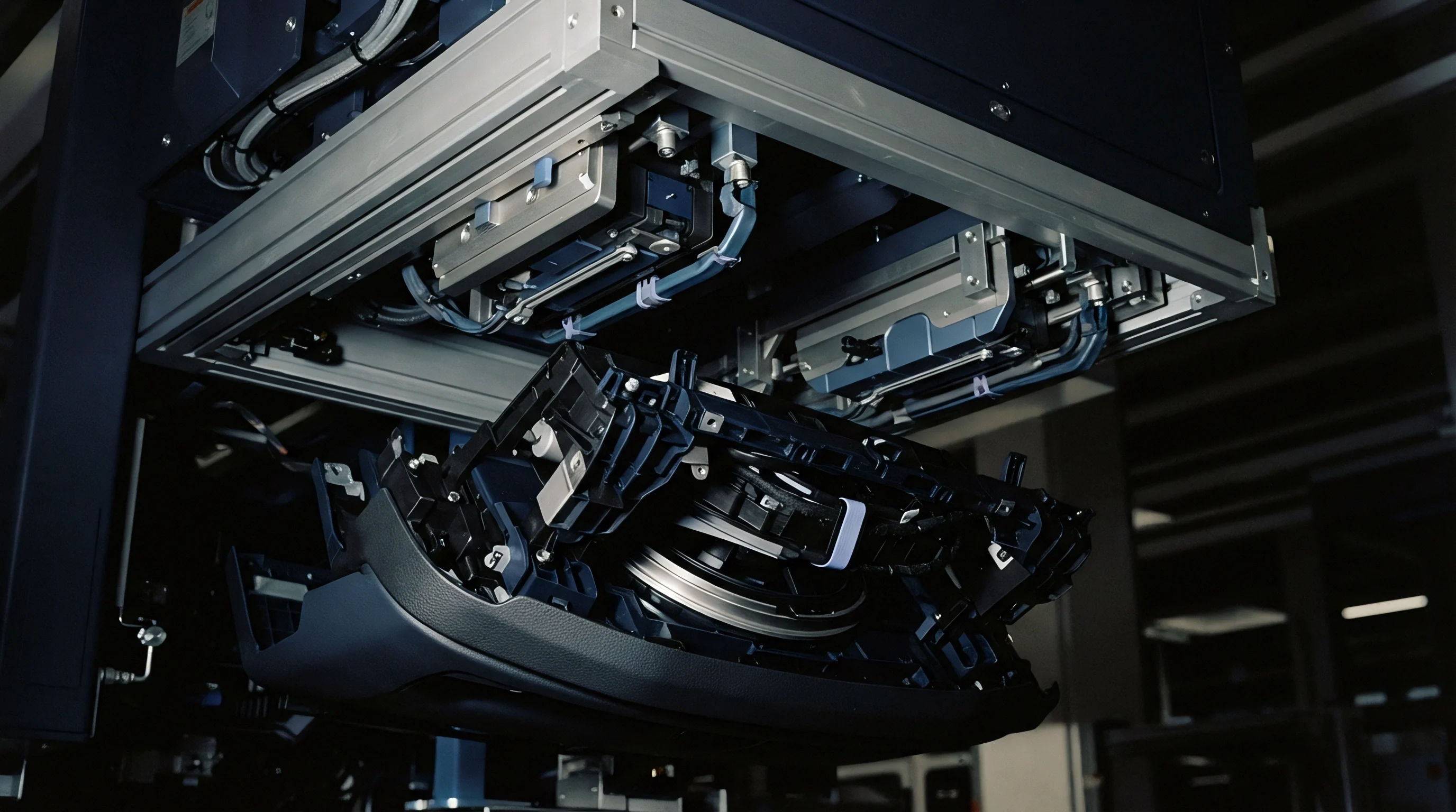

Nest
Secondary ultrasonic tooling cavities support complex injection molded housings during welding, absorbing high-frequency impact while holding features in tight spatial relationship. The internal pocket of a secondary nest mirrors the outer surface of the plastic component. When molding semi-crystalline materials like polybutylene terephthalate or polyamide 66, differential shrinkage introduces spatial variations that the nest pocket must absorb without compromising support directly beneath the weld line.
Machining these contoured pockets typically relies on three-axis or five-axis high-speed CNC milling of 6061-T6 aluminum, PEEK-GF30, or hardened tool steel blocks. Aluminum machines easily and conducts heat well, but it resonates acoustically and wears quickly under continuous cyclic loads. Tool steel delivers far better wear resistance and rigidity, though its added weight and high thermal mass slow down temperature equilibration in climate-controlled metrology rooms.
Choosing a substrate requires balancing machining accuracy, stiffness, damping performance, and long-term dimensional stability.

Material Thermal Coefficients in Fixture Cavities
Thermal expansion mismatches between fixture substrates and plastic workpieces introduce hidden assembly stresses. Aluminum baseplates have a thermal expansion coefficient of roughly twenty-three micrometers per meter-Kelvin, while filled engineering polymers range from twenty to eighty micrometers per meter-Kelvin depending on fiber orientation. In unconditioned plants where floor temperatures swing by fifteen degrees Celsius between shifts, the dimensions of an aluminum nest can drift outside the tolerance band for precision electronic housings.
Elastomeric damping layers behind contoured metal nest inserts absorb residual ultrasonic energy, preventing the fixture from ringing or vibrating in resonance with the horn stack. If these polyurethane or silicone sheets vary in thickness or durometer hardness, the nest yields unevenly under pneumatic force. This uneven compliance cocks the horn relative to the upper joint interface, resulting in asymmetric melt flow, burn marks, and compromised hermetic seals.
| Substrate Material | Coefficient of Thermal Expansion (10⁻⁶/K) | Modulus of Elasticity (GPa) | Surface Hardness (Vickers) | Acoustic Damping Capacity (Ratio) | Machining Tolerance Hold (mm) |
|---|---|---|---|---|---|
| Aluminum 6061-T6 | 23.1 | 68.9 | 107 | 0.0012 | ±0.008 |
| Tool Steel D2 (HRC 60) | 10.4 | 210.0 | 700 | 0.0004 | ±0.003 |
| Titanium Ti-6Al-4V | 8.6 | 114.0 | 349 | 0.0035 | ±0.005 |
| PEEK-GF30 Structural Composite | 22.0 | 9.7 | 45 | 0.0150 | ±0.012 |
| Data evaluated at standard laboratory reference conditions of 20°C and 50% relative humidity under static pre-load of 500 N. | |||||
Titanium Ti-6Al-4V is specified for contoured nests when production runs exceed two hundred thousand cycles. Titanium meets the acoustic impedance demands of high-amplitude operations while providing high mechanical strength and lower thermal conductivity than aluminum. This reduces energy dissipation into the fixture base, directing maximum acoustic energy into the polymer joint interface.

Tactile Scanning Protocols for Contoured Pockets
Verifying the three-dimensional geometry of a contoured nest pocket requires continuous tactile probing on a high-accuracy CMM. Point-to-point probing frequently misses localized machining step-overs, cutter chatter, or electrical discharge machining pits inside deep cavities. Continuous tactile scanning sweeps the entire surface, generating dense point clouds that map deviations directly against the CAD model.
Stylus selection directly affects measurement uncertainty during contour verification. Small-diameter ruby styli on deep cavity sidewalls bend under contact forces above 0.05 Newtons. Carbon fiber shafts paired with large silicon nitride spheres supply the axial stiffness needed to measure deep pockets without false deflection.
Inspection protocols must specify shank length, sphere diameter, contact force, and scanning velocity across all testing sites.
Anodized aluminum pockets require full replacement when surface micro-cracking reaches the elastomeric damping interface behind the cavity insert.
Optical structured-light scanning offers rapid full-field verification of complex cavities, but bright reflections on polished metal distort the output. Metrology labs often apply a micro-thin anti-reflective coating of titanium dioxide powder before scanning. Because coating thickness varies from three to twelve micrometers depending on spray distance and technique, this introduces an uncalibrated dimensional error.
Tactile CMM measurements remain the definitive baseline for high-precision pocket verification.
The following tactile measurement sequence calibrates contoured nest pocket geometries across multiple inspection facilities without introducing operator bias:
- Mount the secondary ultrasonic fixture to the CMM granite bed using three-point kinematic clamps to eliminate mechanical stress deformation.
- Establish the master reference frame using the three permanently mounted ceramic alignment spheres located on the fixture baseplate.
- Hold the fixture for a four-hour temperature stabilization period inside an ISO Class 1 metrology room maintained at twenty degrees Celsius.
- Run a continuous tactile scanning path across internal pocket contours at a maximum speed of five millimeters per second using a stiff carbon fiber stylus.
- Filter raw point cloud data with a Gaussian low-pass spatial filter to isolate macro-geometric form errors from micro-surface roughness.
- Compare the filtered surface directly against the nominal native CAD solid model using a zero-threshold alignment constraint on primary datums.
- Extract clearance values at ten critical cross-sections located beneath the secondary horn joint contact line.
Out-of-spec nest clearance profiles are sometimes rationalized on the assumption that elastic deformation under pneumatic clamp force absorbs internal pocket mismatches. That assumption ignores the residual stress locked into the housing when forced into an incorrect contour. When the ultrasonic horn retracts, the plastic attempts to spring back, introducing permanent bending moments across the welded joint that can lead to latent micro-cracking and seal failures in service.


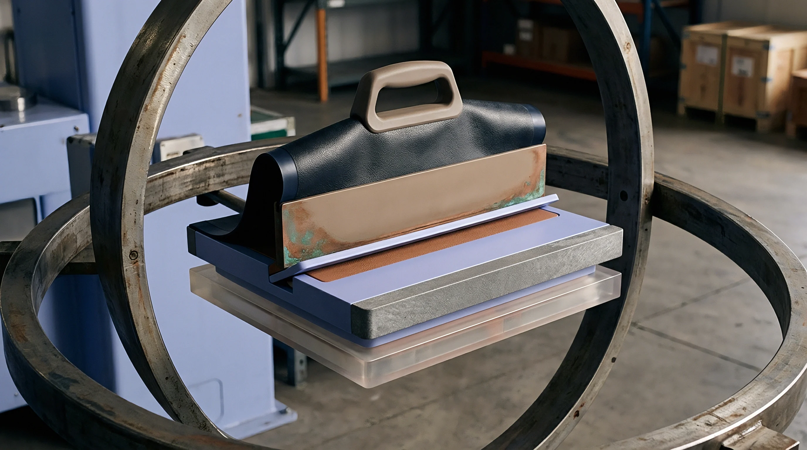
Artifact
Transfer standards ensure that metrology equipment across different plants yields identical dimensional measurements on the same fixture tooling. Physical master artifacts must maintain strict dimensional stability over years of storage and handling. Using actual molded plastic components as transfer masters introduces severe measurement error from moisture absorption, stress relaxation, and mechanical creep.
Stable transfer artifacts rely on zero-expansion glass ceramics like Zerodur or low-expansion nickel-iron alloys such as Invar 36. An Invar master coupon machined to mirror the critical locating features of the plastic housing provides a rigid calibration standard. Seated inside the nest, the coupon lets metrology teams verify positional tolerances, gap spacing, and pin contact points without compliance noise from plastic parts.
Master Part Preservation and Environmental Drift
Ambient humidity significantly alters the dimensions of hygroscopic polymers like polyamide 6 and polyamide 66. A glass-filled nylon master part can absorb up to eight percent moisture by weight in unconditioned environments, expanding by as much as 0.3 percent across key dimensions. If an inspection team uses a nylon reference part calibrated at fifty percent relative humidity in Europe to qualify tooling in a tropical plant, physical expansion of the master conceals an undersized fixture cavity.
Thermal expansion drift reaches twenty-two micrometers at ambient temperatures between nineteen and twenty-nine degrees Celsius, consuming over fifty percent of the total allowable part tolerance band. Metallic and ceramic reference artifacts stored in sealed, desiccant-packed enclosures eliminate moisture expansion, leaving ambient temperature as the sole variable requiring compensation.
| Facility Location | Equipment Variation EV (%) | Appraiser Variation AV (%) | Gauge R&R GRR (%) | Number of Distinct Categories ndc | Ambient Temp Range (°C) |
|---|---|---|---|---|---|
| Facility A (Michigan, USA) | 4.12 | 2.05 | 4.60 | 14 | 20.1 ± 0.5 |
| Facility B (Monterrey, MX) | 8.45 | 5.12 | 9.88 | 7 | 24.5 ± 2.1 |
| Facility C (Suzhou, CN) | 6.30 | 4.80 | 7.92 | 9 | 22.0 ± 1.2 |
| Evaluated per AIAG Measurement Systems Analysis 4th Edition protocols using ten master artifacts across three operators. | |||||

Why Do Optical Scans Fail across Facility Temperature Gradients?
Non-contact optical scanners project light patterns onto a surface and calculate spatial coordinates through stereoscopic triangulation. Ambient lighting, thermal gradients in the measurement volume, and micro-refractions from HVAC airflow all destabilize optical readings. Density shifts in thermal gradients bend light paths, distorting point clouds across large fixture baseplates.
Optical scanners require stable air and light. Thermal plumes from warm machinery near an inspection station alter the refractive index of air along the optical path, corrupting calibration. Enclosing optical metrology cells in rigid, climate-controlled chambers maintains uniform air density, yielding reproducible spatial data that aligns with tactile CMM baselines.
Compliance with ISO 14253-1 dictates the direct subtraction of measurement uncertainty from the allowable part tolerance band prior to approving secondary fixture geometry.
Gauge repeatability and reproducibility studies across multiple sites frequently reveal systemic measurement discrepancies between labs. When total gauge R&R values exceed ten percent of tolerance width, corrective action is necessary. Equipment variation usually stems from worn CMM drives or uncalibrated probe heads, whereas appraiser variation points to inconsistent clamping torque or varied artifact cleaning habits prior to measurement.
Standard quality agreements require compliance with ISO 14253-1 decision rules to prove fixture conformity. Under this standard, the calculated measurement uncertainty of the metrology system is subtracted directly from the drawing tolerance limits. This produces a reduced tolerance band ~ the zone of conformance ~ that shrinks the acceptable manufacturing window.
If a feature falls inside the drawing tolerance but outside the zone of conformance, the receiving plant holds full contractual authority to reject the fixture at the toolmaker’s expense.

Acoustics
High-frequency energy transfer through secondary tooling depends on acoustic resonance and dynamic stability under load. An ultrasonic stack combines a piezoelectric transducer, a mechanical booster, and a custom horn tuned to oscillate at a specific resonant frequency ~ typically twenty thousand or forty thousand cycles per second. Alignment between the vibrating horn face and the stationary nest dictates how uniformly energy enters the joint interface.
Static alignment checks on idle machinery fail to capture deflections that occur during the weld burst. When the pneumatic cylinder drives the horn stack down against the assembly with forces between two hundred and two thousand Newtons, the structural C-frame of the press flexes. This elastic deflection tilts the horn face relative to the nest by several hundredths of a millimeter, concentrating energy along one edge of the energy director while leaving the opposite side unwelded.

Laser Doppler Vibrometry of Welding Horns
Mapping displacement amplitude across an ultrasonic horn face requires non-contact laser Doppler vibrometry. The instrument measures the frequency shift of reflected laser light to determine instantaneous velocity and peak-to-peak amplitude across the vibrating surface. Delivering uniform energy requires that peak-to-peak amplitude varies by less than four micrometers across the entire active face.
Multi-cavity horn faces require dynamic laser vibrometry traces prior to sign-off. If amplitude distribution plots reveal localized nodal points or low-amplitude zones, the horn will fail to melt the energy director simultaneously across all joint locations. Localized amplitude drop-offs usually stem from internal structural resonances, improper horn slitting, or uneven mass distribution from aggressive contour machining on the horn face.
| Trigger Force (N) | Peak Amplitude (μm) | Frequency Shift (Hz) | Stack Impedance (Ω) | Dynamic Angular Tilt (mrad) | Joint Collapse Velocity (mm/s) |
|---|---|---|---|---|---|
| 100 | 32.4 | +12 | 14.2 | 0.08 | 0.42 |
| 300 | 31.8 | -05 | 15.8 | 0.24 | 0.88 |
| 500 | 30.5 | -28 | 18.5 | 0.52 | 1.35 |
| 700 | 28.2 | -64 | 24.1 | 0.91 | 1.72 |
| 900 | 24.9 | -115 | 32.8 | 1.45 | 2.05 |
| Test conducted using a titanium 20 kHz catenoidal horn contacting ABS resin specimens on a rigid steel baseplate. | |||||

Transducer Stack Torque and Impedance Drift
Mechanical interfaces within the acoustic stack require exact assembly torque to maintain structural resonance. Threaded studs joining the piezoelectric transducer, booster, and horn transfer high cyclic tensile and compressive loads. Incorrect stud torque alters the stack’s electrical impedance, leading to power supply overloads, frequency tracking errors, and heat build-up at the interfaces.
Torque directly affects resonant frequency. Under-torquing allows micro-separation at the stud interface, driving acoustic dissipation, fretting corrosion, and eventual fatigue failure. Over-torquing stretches the stud past its elastic limit, distorting mating faces and shifting acoustic impedance.
Calibration protocols should require verified torque wrench settings for all stack assembly across plants.
Uncalibrated horn face amplitude variations exceeding eight percent convert uniform energy directors into localized flash spikes across semi-crystalline joint lines.
Dynamic load cell platforms measure the force profile delivered by the pneumatic actuator throughout the weld cycle. Load cells under the secondary nest capture trigger force ramp-up, weld force maintenance, and hold force dwell. Comparing these force-time curves across production cells exposes regulator hysteresis, cylinder seal drag, and slide binding before mechanical faults compromise part quality.
Calibration dossiers submitted during cross-facility tooling transfers should include the following technical records:
- Static contact alignment scans verifying parallelism between horn face and fixture nest datums within 0.02 millimeters across the full contact length.
- Laser Doppler vibrometry maps displaying full-field peak-to-peak displacement amplitudes measured at 100 percent generator amplitude output.
- Electrical impedance spectra showing resonant frequency, anti-resonant frequency, and total electrical resistance under free-air and loaded conditions.
- Dynamic load cell force traces validating pneumatic trigger accuracy and force stability across operating pressures.
- Thermal imaging profiles capturing temperature distribution across the horn body and stack interfaces during twenty-cycle trial runs.
Questions remain about how high-frequency mechanical fatigue affects the crystal lattice in 3D-printed titanium horns ~ specifically whether localized grain boundary relaxation over several million cycles shifts the resonant node enough to cause weld placement errors across multi-site operations.


Stipulation
Contracts for the fabrication and transfer of secondary ultrasonic fixtures require explicit metrology verification clauses to prevent unexpected re-tooling expense. Quotes frequently omit cross-facility calibration protocols on the assumption that a receiving plant will accept any fixture that produces cosmetic parts during initial dry runs. Once high-volume automated production starts, subtle dimensional errors, uncalibrated trigger forces, and improper nest clearances quickly erode piece-price margins through scrap.
A comprehensive tooling agreement defines the exact metrology standards, instruments, environmental conditions, and statistical acceptance criteria required for final sign-off. Ownership of the fixture stays with the buyer, but risk of geometric non-conformance shifts from toolmaker to moulder only when cross-site metrology dossiers match baseline calibration records. Explicitly defining measurement uncertainty boundaries protects buyers from absorbing the costs of flawed tooling.

Periodic Re-Calibration Volume Triggers
Production fixtures suffer ongoing mechanical wear and micro-fretting. Time-based maintenance schedules often let high-volume lines run worn tooling past accuracy limits while subjecting low-volume lines to premature service. Calibration protocols should enforce volume-based re-calibration tied directly to machine cycle counters.
Triggers mandate full dimensional re-inspection of primary contact points and contoured nest pockets every fifty thousand cycles. If defects like joint flash or leaks exceed fifty parts per million before that threshold, an emergency audit triggers immediately. Replacing worn ceramic pins or elastomeric damping pads restores baseline alignment before wear ruins custom-machined cavities.
Fixture Ownership and Asset Transfer Audit Rules
Moving secondary assembly tooling between sites ~ whether across borders or between contract partners ~ carries real operational risk. Transfer protocols require the exporting plant to complete a calibration audit using certified master artifacts before shipping. The receiving plant repeats that identical audit upon arrival before installing the fixture in a cell.
Comparing pre- and post-shipment metrology dossiers isolates transport damage, warping, and environmental degradation. If post-shipment dimensions deviate from baseline by more than five micrometers, the carrier or exporting facility assumes liability for re-alignment and lost capacity. Formal sign-off requires signatures from quality directors at both sites on a unified metrology certificate.
Asset transfer documentation relies on permanent serial numbers etched into the baseplate and individual cavity inserts. Maintaining historical calibration logs linked to fixture serial numbers creates the audit trail required for medical and automotive compliance. Sourcing strategies that embed strict calibration protocols into initial purchase orders protect part quality, cycle times, and unit economics regardless of where production occurs.