Designing Restrained State Quality Fixtures for Flexible Plastic Assemblies
Restrained state fixtures simulate final assembly fasteners with calibrated clamps on datum targets to measure flexible plastic profiles accurately.

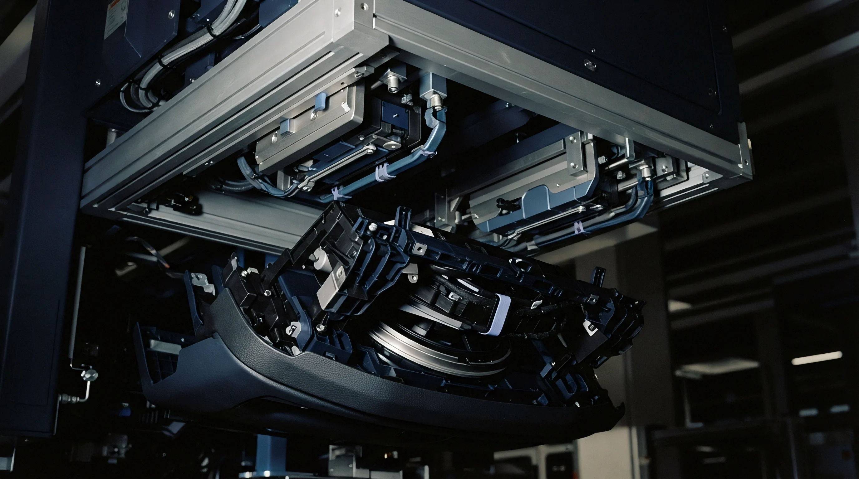
Datum
Free-state injection mouldings and thermoformed panels rarely sit true to their nominal CAD models. Differential cooling, polymer chain alignment along flow fronts, wall section steps, and crystallization combine to warp wide-aspect parts as internal stresses balance out. In vehicle bodies and enclosures, fasteners pull these flexible sections flush against sheet metal or rigid subframes.
Inspection fixtures recreate that fastened state with controlled boundary restraints, following ISO 10579 or ASME Y14.5 restrained condition callouts on the drawing.
Establishing a datum reference frame for compliant plastic means distinguishing between gross free-state relaxation and actual assembly fit. An unreinforced polypropylene cowl with a three-millimeter wall might bow eight millimeters over a 1200-millimeter span on the bench, but drops within 0.5 millimeters of vehicle zero once pinned at its six primary clip towers. The fixture reproduces that installed condition through datum targets, rest pads, locators, and clamps.
Under ASME Y14.5 restrained condition notes, drawings specify clamping sequences and force ceilings directly alongside the datum feature control frames.
Steel net pads on the fixture base are ground to CAD nominal at each functional datum target, while pins set primary, secondary, and tertiary location. ISO 10579 dictates whether inspection runs free-state, fully restrained, or partially constrained with floating secondary features.

Target Placement and Contact Mechanics
Primary datum targets mirror the assembly’s functional contact points. Shifting a datum support away from a fastener zone generates local bending moments under clamp load, which shows up as artificial out-of-tolerance error at outer edges.
Round four-way pins establish origin across two axes, while two-way diamond pins lock rotation while allowing for part shrinkage. Polypropylene or polybutylene terephthalate shrinkage can shift by 0.3 percent between lots based on melt pack pressure and mold temperature; a rigid round pin at the secondary datum would bind in the slot and buckle the part.
Target pads are typically machined from tool steels like AISI O1 or D2 hardened to 58 Rockwell C. Visible class-A surfaces use polished polyoxymethylene or brass contact pads to avoid marking during loading cycles.
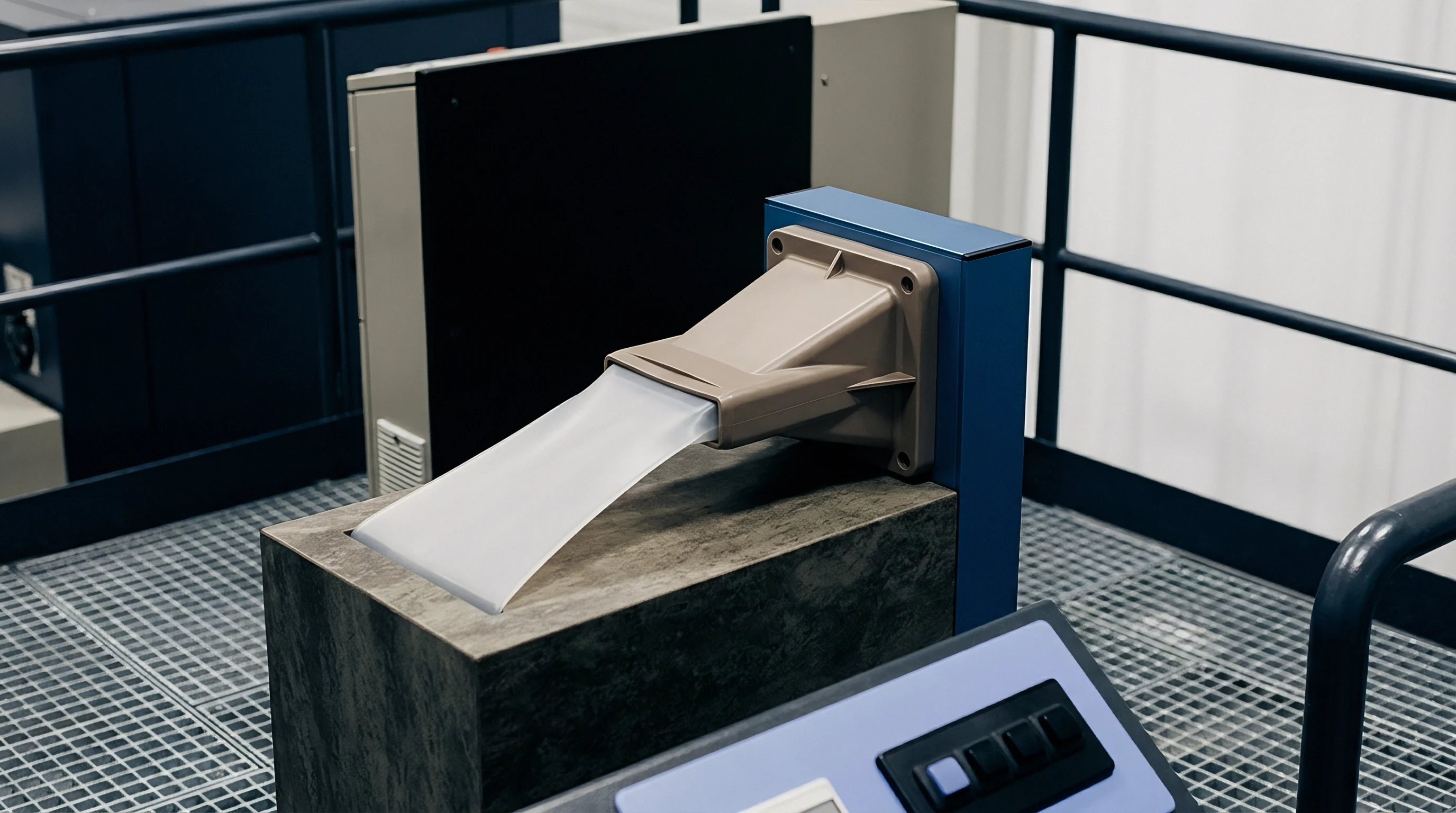
Restraint Force Application Limits
Clamping loads need to match real fastener tension without inducing local plastic strain or oil-canning. Excessive clamping force crushes rib structures and masks severe core warpage that will fail clip towers in service.
Regulated pneumatic toggle clamps ensure consistent loading across shifts. Where manual de-sta-co toggle clamps are used, calibrated spring plungers prevent operator strength from skewing part deflection.
ISO 10579 drawings define clamping force as an upper limit. A standard note might require restraining datum surface A with a maximum of 20 Newtons across four designated targets before measuring edge profile tolerances.
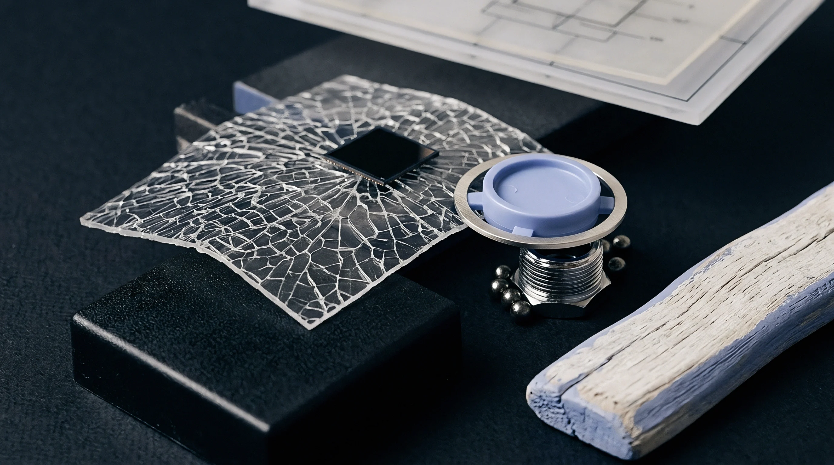

Nest
Inspection plates combine contoured nesting surfaces, sliding blocks, and probe clearance cutouts for coordinate measuring machines or optical scanners. Cast MIC-6 aluminum plate provides a stress-relieved base flat to within 0.1 millimeters per square meter, with uprights and risers dowel-pinned in place to withstand repetitive loading.
Machined nest cavities track CAD geometry with a deliberate 3.00 to 5.00 millimeters offset gap from the part body. This clearance avoids incidental contact with non-datum surfaces, ensuring contact happens only at defined datum targets and designated rest pads.

Are Clamping Sequences Deciding Metrology Repeatability?
Clamping all points simultaneously traps parasitic strain and distorts flexible walls. Fixture designs enforce a specific sequence marked directly on the tool faceplate or inspection sheet.
- Primary target positioning places the raw moulding onto primary Z-axis datum rest blocks under gravitational weight alone.
- Locator pin engagement guides the component over primary four-way and secondary two-way diamond pins without side-load friction.
- Primary clamp activation secures clamps directly opposite primary Z-axis datum pads using calibrated 15 to 25 Newton force plungers.
- Secondary clamp engagement secures secondary boundary locators to remove gross edge flare along flexible flanges.
- Feeler clearance verification confirms full seating against net blocks before initiating sensor data collection.
Altering the clamping sequence on a 1500-millimeter bumper fascia can swing wing-tab profile readings by up to 1.8 millimeters. A fixed clamp sequence removes operator variation during gauge repeatability and reproducibility evaluations.
| Component Category | Material Selection | Hardness / Surface | Positional Tolerance | Operational Role |
|---|---|---|---|---|
| Base Plate | Cast Aluminum MIC-6 | Anodized Clear | 0.02 mm Flatness | Provides dimensionally stable mounting foundation |
| Primary Datum Pads | Tool Steel AISI D2 | 58-62 HRC Ground | ±0.010 mm True Pos | Establishes primary Z-plane mating reference |
| Class-A Rest Blocks | Unfilled POM-C | Natural Machined | ±0.020 mm True Pos | Prevents aesthetic surface marring on show surfaces |
| Locating Pins | AISI O1 Tool Steel | 60 HRC Hard Chrome | ±0.008 mm Diameter | Constrains X-Y translation and axial rotation |
| Swing Clamps | Hard Anodized AL / Steel | Standard Commercial | ±0.5 mm Action Point | Delivers calibrated normal force to datum targets |
Parts passing bench checks can fail inside nested fixtures when fixture binding, rather than part geometry, restricts seating.
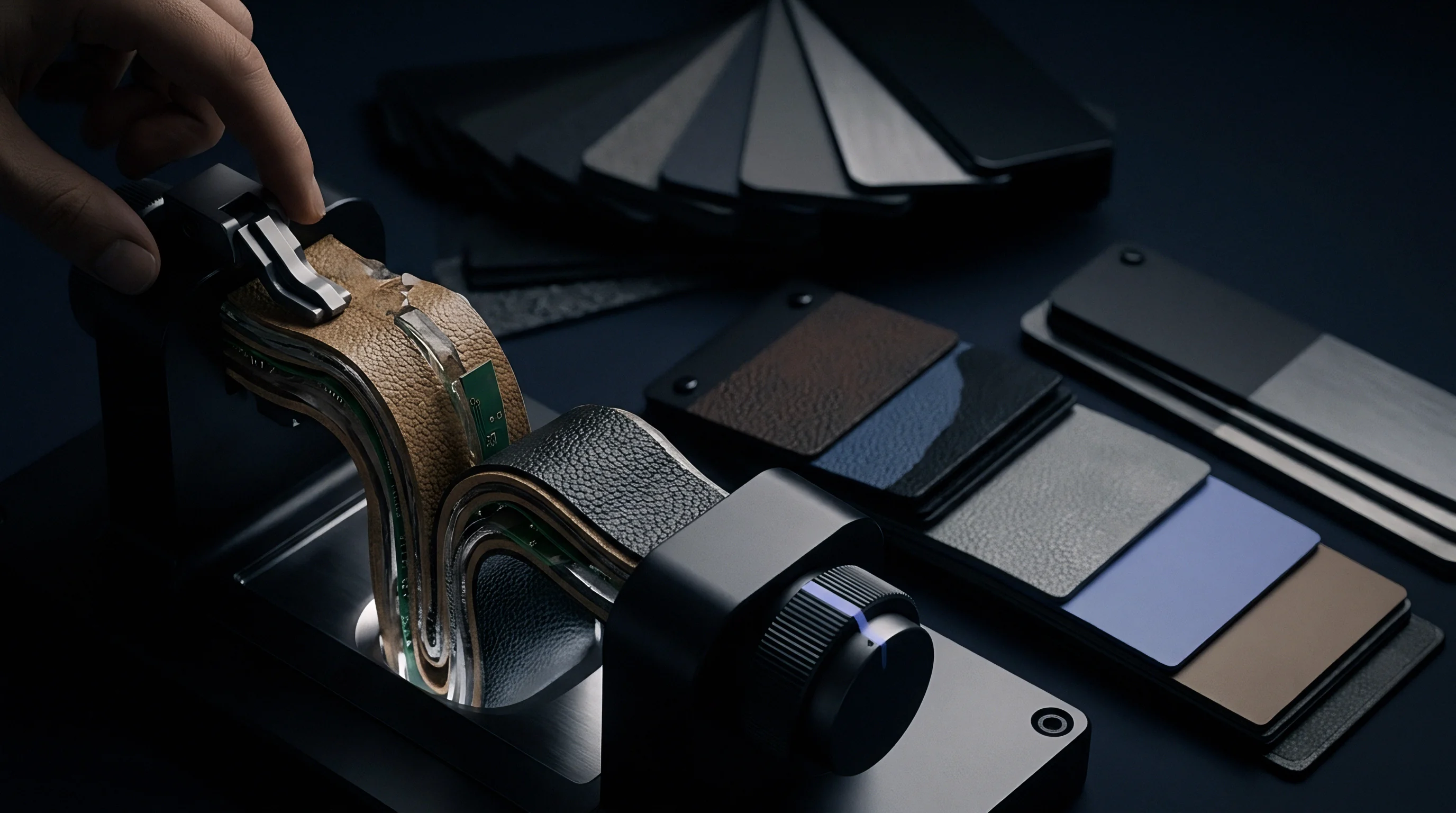

Deflection
Thermoplastics exhibit viscoelastic behavior under load. Clamping a warped moulding against solid fixture pads produces immediate elastic strain followed by time-dependent relaxation and creep. Measuring dimensions during this relaxation phase yields drifting values as polymer chains shift.
Amorphous grades like acrylonitrile butadiene styrene and polycarbonate reach mechanical stability quickly once clamped. Semicrystalline polymers like polyamide 66, polyoxymethylene, and polypropylene continue to creep for several minutes, a process accelerated in polyamides by ambient humidity lowering the glass transition point.
Part deflection under clamping load stabilizes within ninety seconds for unfilled polyolefins at standard room temperature.
Viscoelastic Relaxation Dynamics
Clamping a 4.0-millimeter warped flange against a steel stop creates a reaction force that bleeds off over time depending on flexural modulus, wall thickness, and temperature. Higher shop temperatures lower the instantaneous modulus and make the part seat more easily under the same clamp.
Polypropylene flexural modulus typically runs 1200 to 1600 megapascals at 23 degrees Celsius, but drops below 950 megapascals at 35 degrees Celsius on an unconditioned factory floor. A cylinder deforms the moulding noticeably more in summer plant conditions than inside a 20 degrees Celsius metrology lab, making temperature limits essential for repeatable checks.

Where Do Clamping Forces Induce Artificial Distortion?
Clamp loads applied away from stiffening ribs create local bending moments across thin cover walls.
- Hinged edge rotation occurs when a clamp secures an unribbed perimeter flange, tilting adjacent vertical walls inward toward the component center line.
- Crown oil-canning develops on wide convex panels when secondary clamps force perimeter datums into alignment before central bow settles.
- Pin shear deformation appears when warped fastener holes get forced laterally over rigid locator pins, shearing soft polymer hole perimeters.
- Rib compression sink results from high-force mechanical toggle shoes bearing directly above thin transverse reinforcing ribs.
Finite element analysis during fixture design establishes safe clamping force windows by simulating raw moulded warpage and modeling the stresses introduced as clamps engage the targets.
Seasonal shop temperature swings and resulting relaxation shifts continue to cause gauge correlation splits between tooling vendors and assembly plants.

Metrology
Restrained plastic is measured with optical digitizers or low-force tactile CMM probes. Structured blue-light fringe projection captures full surface point clouds in minutes, while touch probing requires minimal trigger force to avoid flexing unsupported walls during contact.
Tactile probe trigger forces between 0.05 and 0.15 Newtons can deflect a 1.5-millimeter polypropylene trim wall by up to 0.08 millimeters at the touch point. Optical scanning avoids this contact deflection entirely, though shiny surfaces require a thin sublimation spray.
| Measurement Technology | Data Acquisition Speed | Contact Force Influence | Feature Profile Accuracy | Tooling Clearance Demands |
|---|---|---|---|---|
| Tactile CMM Probe | Slow (Discrete points) | 0.02 – 0.10 mm deflection risk | High (±0.005 mm) | Requires 50 mm probe vector clearance |
| Structured Blue Light | Fast (Full surface cloud) | Zero contact deflection | High (±0.015 mm) | Demands line-of-sight visual access |
| Laser Line Triangulation | Medium (Continuous sweep) | Zero contact deflection | Moderate (±0.025 mm) | Requires continuous motion arm clearance |
| Manual Dial Indicators | Real-time (Single location) | Spring load 0.5 – 1.5 N | Low (±0.050 mm) | Integrated directly on fixture frame |

Fixture Cutouts and Sensor Access
Optical scanning needs line-of-sight access to functional datum surfaces, requiring pocketed ribs, skeletal frames, and cutouts behind critical seal tracks and clip towers.
Solid steel clamp arms block target edges from the scanner field. Metrology fixtures use low-profile pneumatic swing arms with relieved composite fingers, or clear polycarbonate pads where fringe patterns must project through the clamping point.
Measurement Uncertainty Chains
Total measurement uncertainty combines fixture machining error, thermal expansion mismatch between aluminum tooling and plastic parts, clamp repeatability, and scanner resolution.
Aluminum expands at roughly 23 microstrain per degree Celsius, compared to 100 to 150 microstrain per degree Celsius for unfilled polypropylene. On a 1000-millimeter moulding, a 5 degrees Celsius shift produces 0.55 millimeters of differential growth. Consistent inspection requires maintaining ambient temperatures at 20 ± 2 degrees Celsius.
Gauge repeatability studies succeed only when thermal stabilization periods match polymer wall thickness.
Disposition
Restrained inspection reports drive production release and mould steel revisions. When a restrained part fails profile tolerances, the priority is distinguishing true tooling steel errors from unstable molding parameters, since cutting steel to compensate for bad fixture data ruins expensive tooling.
Standard verification compares the free-state scan against the restrained scan to calculate the displacement vector field generated by fixture clamping.
High displacement vectors signal severe frozen-in moulding stress. Even if a part fits within profile limits under clamps, residual stresses can trigger stress cracking, fastener fatigue, or warpage during paint bake cycles and solar exposure.
Technicians check cavity pressure curves, gate seal time, and cooling channel balance before authorizing steel changes. Tuning pack and hold stages alone often cuts free-state bow by 40 percent, reducing the force needed to bring datums home against the fixture.
Approving parts based on flawed restraint fixtures leads to high plant rejection rates, broken clip towers during assembly, and early structural failures in the field.