Verifying Polyethylene Density Calibration Using Hydrostatic Testing
Hydrostatic density verification of polyethylene requires fluid thermal stability within ±0.01°C and wire buoyancy correction for 0.0001 g/cm³ accuracy.

Buoyancy
Displacement balance measurements convert mechanical mass differentials into volumetric mass to four decimal places. ISO 1183-1 Method A builds directly on Archimedes’ principle: a solid submerged in fluid experiences an upward buoyant force equal to the mass of the displaced liquid. In semi-crystalline polymers like polyethylene, density acts as the standard proxy for molecular packing, short-chain branching frequency, and overall crystallinity.
A shift of just 0.001 g/cm³ alters tensile yield strength by roughly 1.5 MPa and flexural modulus by up to 40 MPa in high-density formulations. Verifying this value determines whether a resin batch meets the structural demands of pipe grades, blow-molding containers, or geomembranes.
Hydrostatic testing immerses a solid specimen of known dry weight into a liquid bath of known density at a controlled temperature, usually 23.00°C or 20.00°C. The apparent weight loss upon submersion gives the specimen’s exact volume. Polyethylene density ranges from 0.910 g/cm³ in low-density film resins to 0.965 g/cm³ in highly crystalline homopolymers. Because the polymer is less dense than water, testing in pure deionized water requires a sinker or a lighter auxiliary fluid, like ethanol or isopropanol mixtures, to achieve full submersion.
Hydrostatic Force and Archimedes Mechanics
Submerging a non-porous polymer coupon sets up a balance of vertical forces. The true dry mass acts downward under gravity, while the fluid’s buoyant thrust reduces the net force registered by the balance pan. Getting an accurate reading requires correcting for atmospheric buoyancy on the dry sample, tracking the exact fluid density at the moment of measurement, and accounting for the volume displaced by the wire holding the sample basket.
A thin stainless steel or platinum alloy wire connects the balance hook to the submerged basket. Where this wire cuts the liquid surface, a meniscus forms, and surface tension pulls on the wire to skew the force reaching the balance cell. Adding a tiny amount of wetting agent lowers surface tension, but wire diameter itself governs the error.
A 0.1 mm suspension wire keeps surface drag minimal, while a 0.5 mm wire introduces enough drift to distort the fourth decimal place of the final density calculation.
Measuring an ISO 1183-1 Method A density of 0.9540 g/cm³ at 23.00°C requires fluid thermal stability within ±0.01°C to prevent displacement float errors.
Thermal Sensitivity of Immersion Liquids
Immersion liquids expand significantly over narrow temperature ranges. At 23°C, the thermal expansion coefficient of distilled water is roughly 0.00023 per degree Celsius. Isopropanol sits much higher, near 0.00105 per degree Celsius, leaving solvent baths far more vulnerable to ambient room fluctuations.
A temperature offset of just 0.2°C in an ethanol mixture shifts calculated HDPE density by 0.0003 g/cm³, which is enough to fail a standard resin qualification.
Holding bath temperatures within ±0.01°C keeps reference table density figures valid across an entire test run. Calibrated quartz thermometers or secondary platinum resistance sensors mounted right beside the submerged sample track temperature continuously. The table below details common immersion liquids, baseline densities, and thermal expansion coefficients for calibration setups.
| Immersion Liquid Medium | Nominal Density (g/cm³) | Thermal Coefficient (g/cm³/°C) | Recommended Polyethylene Density Range |
|---|---|---|---|
| Deionized Water with 0.1% Surfactant | 0.9975 | -0.00023 | 0.910 to 0.970 (Requires Sinker) |
| Isopropanol (Analytical Grade 99.9%) | 0.7831 | -0.00084 | 0.910 to 0.970 (Direct Submersion) |
| Ethanol/Water Blend (50/50 Volumetric) | 0.9263 | -0.00062 | 0.935 to 0.970 (Direct Submersion) |
| n-Heptane (Reference Grade) | 0.6837 | -0.00087 | 0.910 to 0.950 (Direct Submersion) |
Interactions between the molded plaque surface and the fluid boundary layer can still introduce minor uncertainties in local surface tension over long testing runs.
Bath
Precision testing requires tight control over surface tension to stop micro-bubbles from clinging to sample edges. Air pockets sticking to hydrophobic polyethylene add extra buoyant volume, driving the calculated density down. A single bubble just 0.5 mm across contributes about 0.000065 grams of buoyant lift.
On a 1.0000 gram specimen, that single bubble drops the calculated density by over 0.0005 g/cm³, causing a good pipe-grade resin to fail incoming quality control.
Hydrostatic test stations typically mount the fluid vessel inside a double-walled jacket connected to a circulating chiller. Drafts blowing across an open liquid surface trigger convection currents inside the vessel, creating local density gradients that exert upward or downward drag on the sample basket. Housing both the analytical balance and the bath inside a draft shield prevents air interference and holds fluid temperature steady.
Wet Bench Environment and Fluid Chemistry
Fluid purity directly affects test repeatability. Evaporation constantly shifts the ratio of alcohol-water mixtures, altering reference density over the course of a single shift. Meanwhile, open deionized water absorbs carbon dioxide and atmospheric gases, forming microscopic nucleation sites on the vessel walls and suspension wire.
Degassing the liquid under vacuum for 30 minutes prior to testing strips out dissolved gases and prevents bubbles from forming on submerged samples.
Isopropanol wets non-polar polyethylene easily, preventing surface bubbles without extra additives. Solvent mixtures like ethanol can, however, swell low-molecular-weight polymer fractions over prolonged exposure. Leaving a compression-molded coupon in an alcohol bath for more than five minutes allows solvent absorption that inflates measured mass.
Completing weighings within two minutes of submersion limits solvent diffusion into the matrix.
Surfactant Dosing for Bubble Suppression
Dosing deionized water with a non-ionic surfactant drops surface tension from 72.8 mN/m to under 30 mN/m at 23°C. Non-foaming additives like Triton X-100 or alkyl phenoxy polyethoxy ethanol promote wetting at volume concentrations between 0.01% and 0.1%. Excess surfactant causes foaming when the basket is lowered, creating foam pockets that prove harder to dislodge than standard air bubbles.
While surfactants lower surface tension rapidly, continuous bath monitoring is necessary to prevent gradual test drift over daily operations.
- Bubble Entrapment occurs when air gets trapped inside surface scratches, tool marks, or stamped sample lettering during submersion.
- Fluid Evaporation changes alcohol-to-water ratios in mixed baths, causing steady drift in the reference fluid density.
- Convection Currents develop from thermal gradients in uninsulated baths, applying dynamic drag or lift to the weighing pan.
- Solvent Swelling inflates apparent coupon mass when non-polar polymers soak too long in alcohol media.
Strict thermal control is essential for reliable fourth-decimal accuracy, and keeping immersion media clean stops unexpected baseline shifts.
Adding excess surfactant causes foaming during basket placement, creating surface bubbles that corrupt density readings.
Relying on unverified fluid density tables leads directly to measurement errors within a couple of operational shifts.
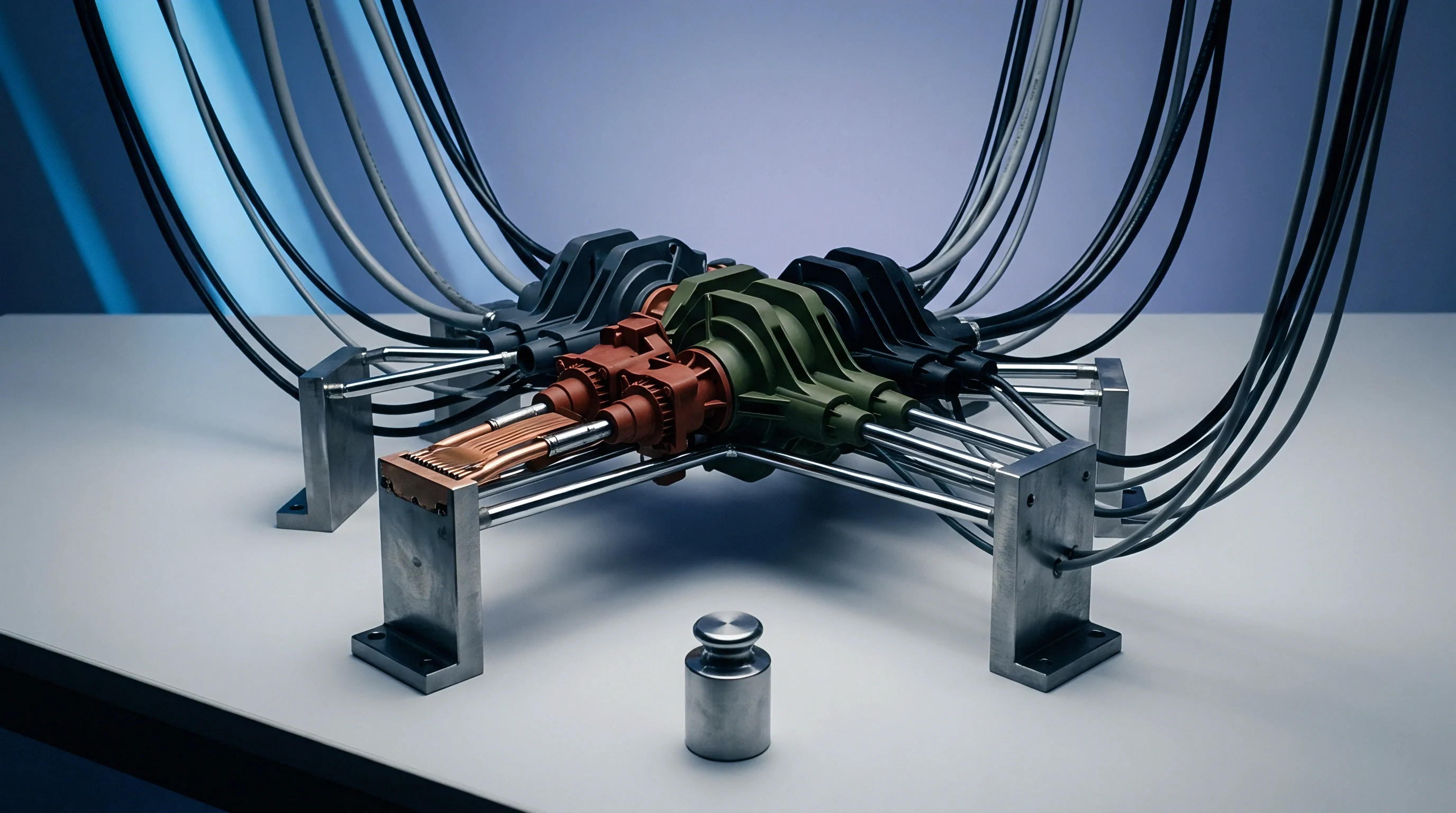
Specimen
Compression-molded test plaques lock in chain alignment based on how they are cooled. Because polyethylene is semi-crystalline, its measured density depends heavily on thermal history during plaque preparation. Fast cooling prevents polymer chains from folding into ordered lamellae, producing lower crystallinity and lower density.
Slow cooling gives lamellae time to grow, increasing overall crystallinity and measured density. ISO 293 and ISO 17855-2 specify precise cooling schedules, such as Method C at 15°C/min, to establish reproducible reference states.
Testing samples cut directly from extruded pipe, blown film, or injection-molded parts reflects structural density rather than true base resin density. Mold alignment, shear-induced crystallization, and cooling gradients build density variations across a single part. Standard lot verification requires molding and conditioning plaques under controlled conditions to erase processing history.
Annealing specimens in an inert gas oven relieves residual stress and stabilizes crystal structure before immersion.
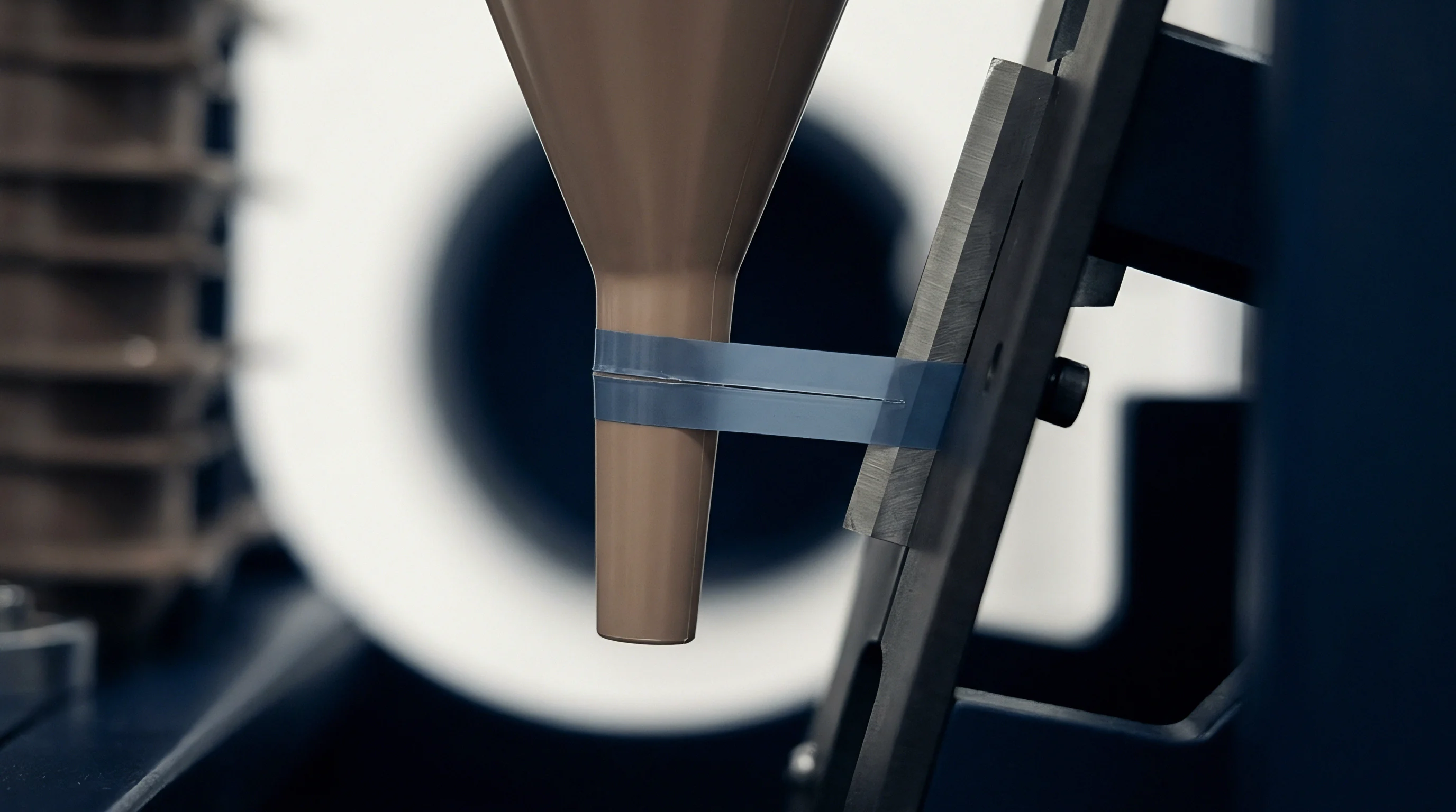
Compression Molding and Cooling Rate History
Preparing specimen coupons requires careful handling to prevent voids, sink marks, and surface contamination. Gas released during platen heating can form microscopic internal voids within the plaque. These voids act as internal air pockets, depressing the apparent density of the polymer matrix.
Running a vacuum degas cycle while the resin is molten draws off volatile gases and trapped air before full compression.
Controlling cooling rates is critical when comparing density measurements across different labs. A plaque cooled at 50°C/min can test up to 0.004 g/cm³ lower than the exact same resin cooled at 5°C/min. When comparing incoming shipments against supplier data sheets, testing labs must match the precise cooling profile named in the material standard.
The table below illustrates density shifts across various cooling profiles for medium- and high-density resins.
| Resin Grade Designation | Nominal Melt Index (190°C/2.16kg) | Quenched Cooling Density (g/cm³) | Standard Cooling 15°C/min (g/cm³) | Annealed State Density (g/cm³) |
|---|---|---|---|---|
| LLDPE Hexene Copolymer | 1.0 g/10 min | 0.9162 | 0.9195 | 0.9221 |
| MDPE Pipe Compound Base | 0.2 g/10 min | 0.9351 | 0.9388 | 0.9415 |
| HDPE Injection Molding Grade | 7.0 g/10 min | 0.9502 | 0.9545 | 0.9582 |
| HDPE Bimodal Pipe Grade (PE100) | 0.25 g/5.0kg | 0.9461 | 0.9498 | 0.9531 |
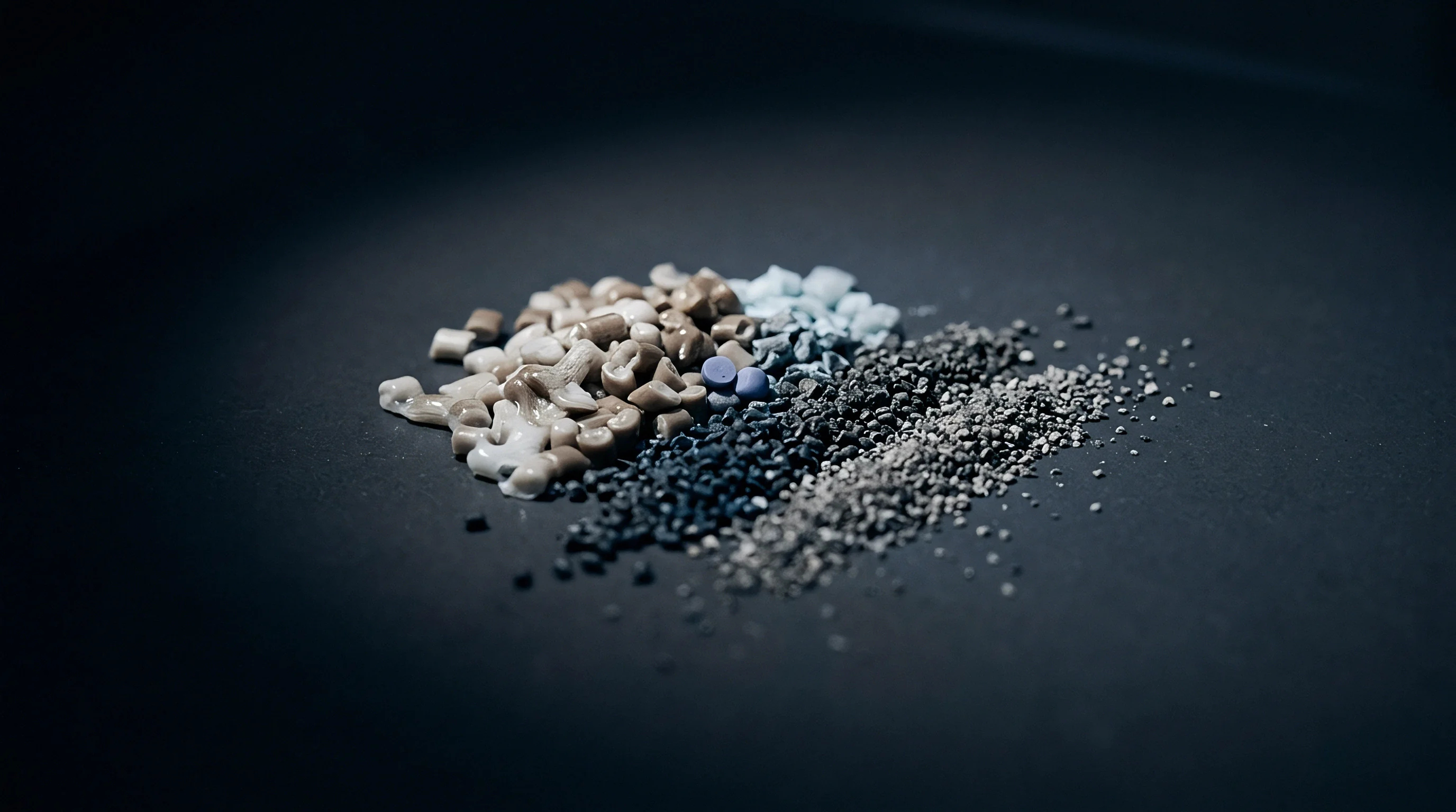
Is Displacement Method a Valid for Filled Polyethylene Grades?
Mineral fillers, carbon black, and heavy pigments increase compound density dramatically. Method A calculates total compound density without separating the polymer matrix from inorganic additives. Calcium carbonate (2.71 g/cm³) or talc (2.75 g/cm³) shifts density noticeably at loadings as low as 1%.
Similarly, carbon black added for UV stabilization in PE100 pipe compound raises density from 0.949 g/cm³ to around 0.959 g/cm³ at 2.25% weight loading.
Because matrix density dictates long-term performance, verifying base polymer density in filled compounds requires solvent extraction or pyrolytic ash testing per ISO 3451-1 to isolate inorganic content. Calculating true matrix density then requires subtracting filler mass and volume from the hydrostatic result. Ignoring filler content leads to misclassifying base resins and miscalculating long-term hydrostatic strength.
ASTM D4976 requires thermal conditioning of molded plaques at 23°C for 40 hours before hydrostatic testing to reach crystalline equilibrium.
Inconsistent sample cooling invalidates incoming resin checks, triggering false non-conformance rejections that disrupt production and cause supplier disputes.
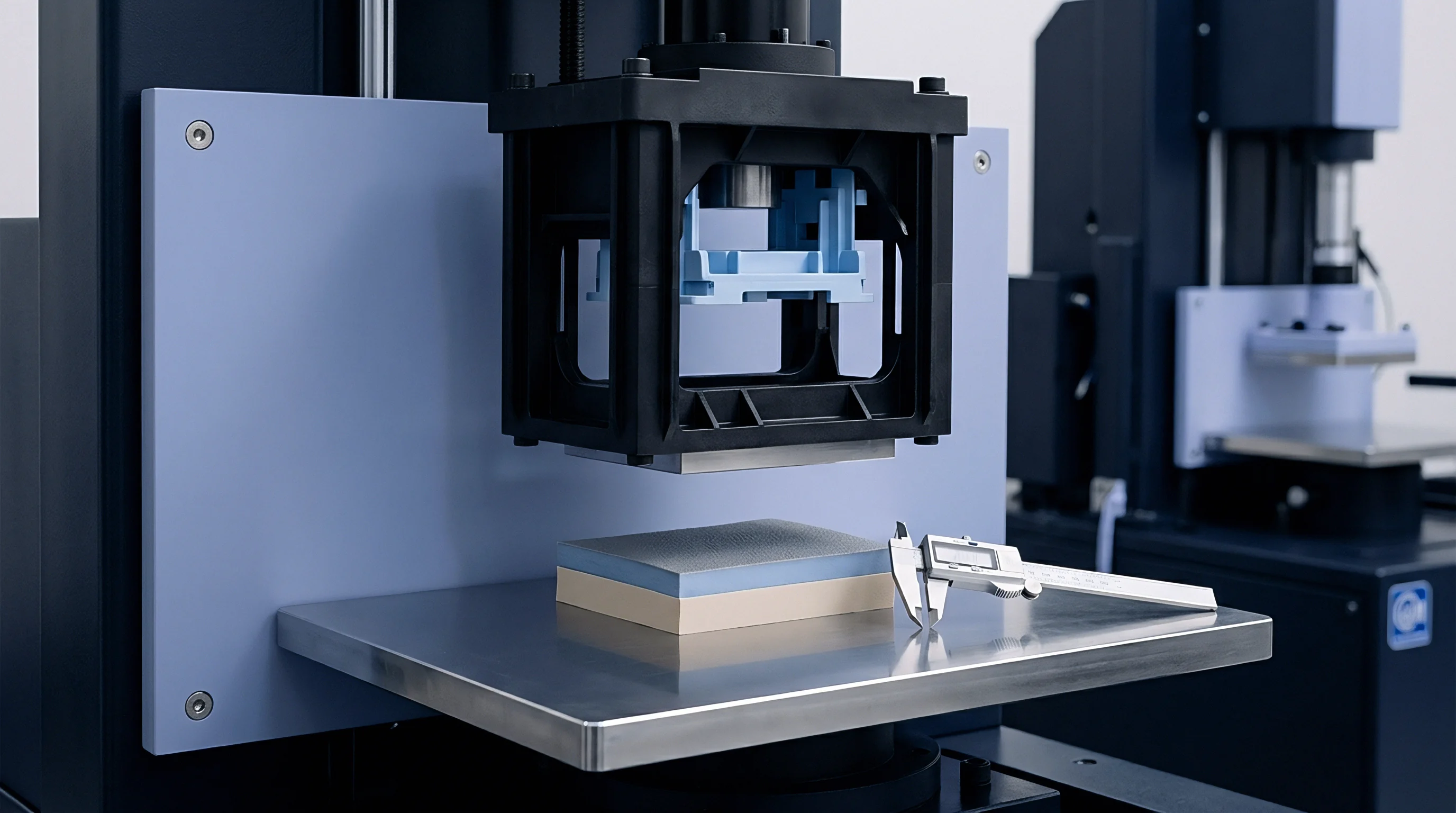

Arithmetic
Hydrostatic calculations blend dry and submerged mass readings with temperature-corrected fluid densities. The governing equations in ISO 1183-1 Method A determine specimen density at 23°C while correcting for buoyancy effects.
Calculating the density of a solid submerged in fluid follows this basic relationship:
Density = (Mass in Air Fluid Density) / (Mass in Air - Mass in Liquid)
This basic equation assumes air density is negligible. However, achieving accuracy down to 0.0001 g/cm³ requires correcting for air buoyancy on both the sample and balance weights. At 23°C and 101.325 kPa, air density is about 0.0012 g/cm³.
Ignoring it introduces a systematic error of roughly 0.0011 g/cm³, distorting reported polymer properties.
Mathematical Calibration and Wire Buoyancy Corrections
The suspension wire adds a displacement error during submerged weighing. As the empty holder sinks, the wire displaces fluid along its immersed length. Taring the balance with the empty basket suspended in the liquid zeros out the static mass of the wire and basket, though surface tension drag at the liquid-air interface can still create minor force shifts when the sample is loaded.
Mathematical corrections compensate for wire volume when sample mass is small. On coupons weighing under 0.5 grams, wire drag creates noticeable variance. Using larger coupons ~ between 2.0 and 5.0 grams ~ reduces the relative impact of surface drag below the balance detection threshold.
Worked Density Error Budget Walk
Consider an HDPE coupon weighed to 0.0001 grams in a water bath with 0.05% surfactant at 23.0°C. Dry specimen mass in air is 2.4512 grams, while apparent submerged mass in the water basket is 0.1345 grams. Reference density of the surfactant-dosed water at 23.00°C is 0.99752 g/cm³, and air density is 0.00120 g/cm³.
Calculating without air correction yields:
Uncorrected Density = (2.4512 0.99752) / (2.4512 - 0.1345) = 2.44512 / 2.3167 = 1.0554 g/cm³
Because polyethylene floats in water, this calculation requires a sinker. Assume a calibrated sinker weighing 10.0000 grams in air and 8.7000 grams in water holds the sample submerged. Combined mass of sample and sinker in water reads 8.8345 grams.
Net submerged mass of the sample equals 8.8345 minus 8.7000, giving 0.1345 grams of upward buoyancy. The standard formula for a floating polymer using a sinker is set up as follows:
Polyethylene Density = (Mass of Dry Sample Liquid Density) / (Mass of Dry Sample + Mass of Sinker in Liquid - Combined Submerged Mass)
Substituting the verified operational figures into the formula gives:
Polyethylene Density = (2.4512 0.99752) / (2.4512 + 8.7000 - 8.8345) = 2.44512 / 2.3167 = 0.9416 g/cm³
Applying the rigorous air buoyancy correction formula from ISO 1183-1 adjusts the calculated figure:
Corrected Density = + Air Density
Corrected Density = + 0.00120 = 0.9416 g/cm³
Analytical balance resolution establishes the floor for four-decimal accuracy, where even a 0.01°C bath drift distorts the calculation.
- Zero the analytical balance with draft shields closed, cleaning the pan with an anti-static brush.
- Place the vessel of degassed liquid on the balance bridge, taking care that the vessel does not touch the pan mechanism.
- Lower the suspension wire and basket into the fluid to the established fill line.
- Tare the scale to read 0.0000 grams with the submerged basket suspended in the liquid.
- Place the dry specimen on the upper pan to record mass in air to 0.0001 grams.
- Transfer the specimen into the submerged basket using non-magnetic forceps, dislodging any visible air bubbles.
- Record the submerged mass reading once the stability indicator locks, recording bath temperature at that exact moment.
Unfilled resin density directly reflects backbone branching, making accurate execution critical for verifying compliance with supply specifications.
The hydrostatic density equation requires real-time fluid temperature logging to maintain fourth-decimal validity.
Minor density variances may stem from atmospheric pressure shifts rather than underlying polymer composition changes.
Compliance
Quality certificates accompanying railcar deliveries state density measured under factory reference conditions. Plants rely on these Certificates of Analysis (CoA) to unload raw material into storage silos. Discrepancies between supplier CoA figures and incoming verification tests cause immediate commercial friction, risking batch rejections and plant delays.
Aligning thermal conditioning and testing protocols between buyer and supplier prevents these artificial test mismatches.
Commercial agreements specify tolerance bands around nominal density targets. Film-grade LLDPE typically allows a variation of ±0.0010 g/cm³ around a 0.9180 g/cm³ target. For high-density pipe resins, that window tightens to ±0.0005 g/cm³ to protect long-term pressure ratings.
Drifting outside these limits alters extrusion wall thickness, driving up resin consumption or reducing part burst strength.

Certificate of Analysis Auditing and Lot Acceptance Limits
Receiving inspection catches lot-to-lot variation before resin enters compounding hoppers. When a railcar arrives with 90 tonnes of pellets, composite sampling across multiple hatches provides representative material. Testing three separate compression-molded plaques per sample set confirms batch homogeneity.
The table below summarizes tolerance windows and operational risks across major resin categories.
| Polyethylene Resin Application | Target Density (g/cm³) | Standard Tolerance Window | Operational Risk of Off-Spec Density |
|---|---|---|---|
| Rotational Molding Grade (LLDPE) | 0.9350 | ±0.0015 g/cm³ | Warping, reduced impact resistance at sub-zero temperatures |
| PE100 Pressure Pipe Grade (HDPE) | 0.9590 (Pigmented) | ±0.0005 g/cm³ | Failure of 100-year stress regression curve qualification |
| Thin-Wall Injection Molding (HDPE) | 0.9520 | ±0.0010 g/cm³ | Inconsistent mold shrinkage, part ejection sticking |
| Blow Molding Container Grade (HDPE) | 0.9550 | ±0.0008 g/cm³ | Environmental stress crack failure, top-load crush failure |
Sourcing Contract Terms and Verification Gates
Defining explicit density testing protocols in procurement contracts prevents off-spec resin deliveries. Complete specifications name the exact standard, method variant, plaque cooling rate, and immersion fluid. For example, referencing ISO 1183-1 Method A with plaque cooling per ISO 17855-2 Method C removes ambiguity surrounding sample thermal history.
Verifying certificate claims through receiving inspection maintains raw material traceability across complex supply chains.
- Method Alignment Clauses mandate that incoming verification tests replicate supplier test equipment and plaque cooling schedules.
- Arbitration Retain Samples require storing sealed pellet samples from every railcar for joint lab re-testing during disputes.
- Tolerance Threshold Limits set boundary conditions that trigger price adjustments or complete lot rejections.
- Third-Party Recourse designates accredited referee laboratories to issue binding density readings when disputes arise.
Contracts incorporating ISO 1183-1 Method A specify density testing at 23.00°C ± 0.10°C in degassed deionized water, with plaque preparation following ISO 293 Method C cooling, binding both supplier and purchaser to the exact same analytical workflow.