Viscoelastic Polymer Residual Stress Calculation Methods for Variable Mold Cavities
Coupling full 3D viscoelastic finite element modeling with Prony series relaxation spectra predicts residual stress and prevents post-molding warp in variable cavities.
Wall
Injection molding of parts featuring step-down features, varied rib attachments, or progressive wall taper introduces distinct thermal histories within a single cavity. Liquid polymer entering a variable cavity contacts tool surfaces maintained below the material transition temperature, instantly forming a frozen skin layer. The thickness of this frozen boundary scales inversely with local flow velocity and directly with thermal conduction time.
In thick regions, slow cooling keeps the polymer core above its glass transition temperature or crystallization temperature long after thin sections have fully solidified. This differential thermal isolation creates localized cooling rates ranging from 50 degrees Celsius per second in thin features to less than 2 degrees Celsius per second within heavy bosses.
Volumetric shrinkage proceeds heterogeneously across these cross-sectional transitions. As the inner core cools and shrinks, the outer solidified skin resists deformation, generating compressive stresses in the exterior layers and high tensile stresses within the interior core. When nominal wall thickness varies by more than thirty percent over short spatial distances, the localized thermal mass differential overwhelms standard packing pressure propagation.
Amorphous polycarbonate molded at a tool wall temperature of 85 degrees Celsius retains localized frozen-in tensile stresses exceeding 22 megapascals when nominal wall thickness varies by more than forty percent across a distance of five millimeters.

Thermal Mass Disparities and Local Core Freeze Mechanics
Cooling times scale quadratically with section thickness according to Fourier heat conduction equations. A two-millimeter section completes solidification in roughly four seconds, whereas a four-millimeter section requires nearly sixteen seconds under identical mold boundary conditions. During this extended time delta, the core of the thicker region remains mobile while adjacent thin walls freeze completely, blocking downstream pressure transmission.
The resulting isolation prevents supplementary pack pressure from compensating for localized volumetric shrinkage.
Calculations evaluating residual stress formation must track the temperature profile across the full cavity thickness at discrete temporal increments. Thermally induced stress components emerge when temperature gradients decay non-linearly through the thickness. The local stress tensor evolves as a function of the instantaneous thermal expansion coefficient, shear modulus development, and localized cooling velocity.
| Polymer Matrix Type | Wall Step Ratio (Thin to Thick) | Cooling Rate Ratio | Peak Core Tensile Stress (MPa) | Peak Skin Compressive Stress (MPa) |
|---|---|---|---|---|
| Unfilled Polycarbonate | 1.5 to 3.0 mm | 3.8 to 1 | 18.4 | 24.1 |
| 30 Percent Glass Polyamide 66 | 1.5 to 3.0 mm | 4.2 to 1 | 26.7 | 31.5 |
| Acrylonitrile Butadiene Styrene | 2.0 to 4.0 mm | 3.9 to 1 | 14.2 | 19.8 |
| Unfilled Polypropylene | 2.0 to 4.0 mm | 4.5 to 1 | 11.6 | 15.2 |
Volumetric Shrinkage Differential in Non-Uniform Sections
Polymer volume contracts upon cooling due to density increases from thermal contraction and phase transformation during crystallization. In semi-crystalline polymers like polyoxymethylene or polybutylene terephthalate, latent heat release during crystal formation extends the core cooling plateau, amplifying internal stress peaks. In amorphous materials like polymethyl methacrylate, volumetric changes depend primarily on the temperature derivative of specific volume above and below the glass transition point.
Geometric constraints imposed by adjacent rigid sections prevent uniform contraction. The constrained contraction converts potential volumetric strain into physical stress. Neglecting the interaction between wall step ratios and volumetric shrinkage yields unexpected warp that forces late tool steel modifications, adding weeks to program timelines and increasing tooling modification budgets.
Spectrum
Viscoelastic materials store and dissipate mechanical energy simultaneously under deformation. Modulus decay occurs over broad time scales, requiring a continuous or discrete spectrum of relaxation times to represent the constitutive behavior. The relaxation modulus G(t) in linear viscoelasticity is described by a Prony series representation expressed as:
G(t) = G_infinity + sum_{i=1}^{N} G_i exp(-t / tau_i)
where G_infinity represents the long-term equilibrium modulus, G_i denotes the relaxation strengths, and tau_i defines the discrete relaxation times spanning from microsecond molecular rearrangements to long-term chain reptation mechanisms.
Temperature shifts accelerate or retard these relaxation processes according to time-temperature superposition principles. Above the glass transition temperature, the shift factor a_T follows the Williams-Landel-Ferry relationship:
log10(a_T) = -C1 (T – T_r) / (C2 + T – T_r)
where C1 and C2 are material-specific empirical parameters, T is the local processing temperature, and T_r is the reference glass transition temperature. Below the glass transition region, the shift factor departs from Williams-Landel-Ferry behavior and transitions to an Arrhenius dynamic, where temperature dependence relies on structural thermal history and fractional free volume decay.
Prony Series Formulations for Thermoviscoelastic Stress Relaxation
Predicting residual stress in variable mold cavities demands mapping the Prony series parameters against instantaneous thermal histories. During rapid cooling in thin cavity zones, the effective material time shifts faster than mechanical stress can relax, locking high unrelaxed stress states into the matrix. Conversely, slow cooling in thick sections allows low-end spectrum modes (tau_i under 0.1 seconds) to fully decay before the material achieves dimensional stability.
Higher cooling rates shift the effective glass transition zone downward in temperature, freezing unrelaxed orientation stress deeper into the core layer.
Accurate mathematical calculation requires integrating incremental thermorheological strains over the transient thermal history. The governing hereditary integral computes stress tensor evolution as:
sigma(t) = integral_0^t 2 G(xi(t) – xi(t’)) (d e_dev / dt’) dt’ + I integral_0^t K(xi(t) – xi(t’)) (d e_vol / dt’) dt’
where xi represents reduced time, e_dev is the deviatoric strain tensor, e_vol is the volumetric strain tensor, and K defines the bulk modulus relaxation spectrum.

Non-Linear Viscoelasticity under Variable Packing Pressures
Pressure exerts a profound influence on free volume, directly altering relaxation times during the packing phase. Elevating cavity pressure by 50 megapascals increases the effective glass transition temperature by approximately 10 to 15 degrees Celsius for amorphous resins. This pressure-induced shift solidifies the melt core prematurely at elevated temperatures, shifting the relaxation spectrum toward longer times.
Matching the longest discrete relaxation time of the polymer spectrum to the cavity pressure holding window prevents post-ejection stress relaxation and dimensional drift.

Pressure
Pressure trajectories within a variable mold cavity govern the transition from viscous fluid flow to viscoelastic solid state. High injection velocity induces intense shear strain rates near the cold cavity wall, generating flow-induced molecular orientation residual stress. As the mold fills, shear stress peaks within the frozen layer interface.
During the subsequent packing phase, hydrostatic cavity pressure compresses the cooling polymer, attempting to offset thermal contraction.
In asymmetric cavities containing both 1-millimeter ribs and 4-millimeter main bodies, cavity pressure decays unevenly. Pressure sensors located near the gate record extended pack cycles, while sensors downstream of thin-wall restrictions detect early pressure cut-off. Early gate seal or thin-section freeze isolates the thick cavity region, dropping local pressure to atmospheric while the core remains molten.
Decoupling Flow Induced Shear Stress from Thermal Residual Stress
Flow-induced stress originates from molecular chain stretching along the main flow path during cavity filling. Highly oriented chains freeze in position near the mold surface due to extreme wall heat transfer. Thermal residual stress arises later during cooling, driven by differential thermal expansion across the cross-section.
Flow-induced residual stresses concentrate within a narrow layer 0.05 to 0.2 millimeters below the part surface, whereas thermal stresses span the entire cross-sectional profile.
Gate Seal Timing in Asymmetric Cavity Volumes
Gate sizing and placement dictate the duration of effective pressure packing. When a single gate feeds a cavity with variable thickness, packing pressure remains active only until the thinnest flow passage or gate freezes. Early gate freeze leaves thick zones unpacked, promoting void formation or elevated tensile stresses in the core.
Sizing gates to the thickest section wall or implementing valve-gated sequential injection provides active pressure control across disparate cavity features.
- Gate area sink formation occurs when core cooling exceeds volumetric pack compensation following premature gate freeze-off.
- Unbalanced shear orientation stress develops when melt forces through narrow restriction channels prior to entering broad cavity sectors.
- Core void cavitation manifests in heavy wall regions when exterior skin rigidity resists inward thermal contraction under zero hydrostatic packing pressure.
- Post-molding warpage driving torque emerges when asymmetric thermal stresses create unbalanced bending moments across thin planar surfaces.
Specifying stress relaxation evaluation under ISO 18437 mandates dynamic mechanical analysis across the full thermal window, preventing premature part cracking during post-mold assembly.
Toolmakers frequently assert that increasing pack pressure cures localized sink and stress, whereas excessive packing actually locks elevated compressive stresses into the gate area and generates severe tensile stress peaks at thick-to-thin transitions.

Mesh
Numerical simulation of viscoelastic residual stress in variable cavities requires matching spatial discretization to physical process complexity. Traditional 2.5D midplane shell algorithms employ Hele-Shaw flow assumptions, neglecting cross-plane shear components and three-dimensional heat conduction at wall thickness steps. Shell solvers perform adequately in thin, uniform planar structures but fail to capture full out-of-plane stress distributions at sudden section changes, geometric fillets, or complex rib intersections.
Full 3D finite element solvers discretize the physical volume using solid tetrahedral or hexahedral elements. Solid elements compute temperature, velocity, and pressure fields across all spatial coordinates without midplane simplification. Hexahedral boundary layer meshing near mold walls resolves high thermal gradients and rapid shear rate variations within the skin layer.
How Do Three Dimensional Mesh Solvers Capture Flow Induced Birefringence?
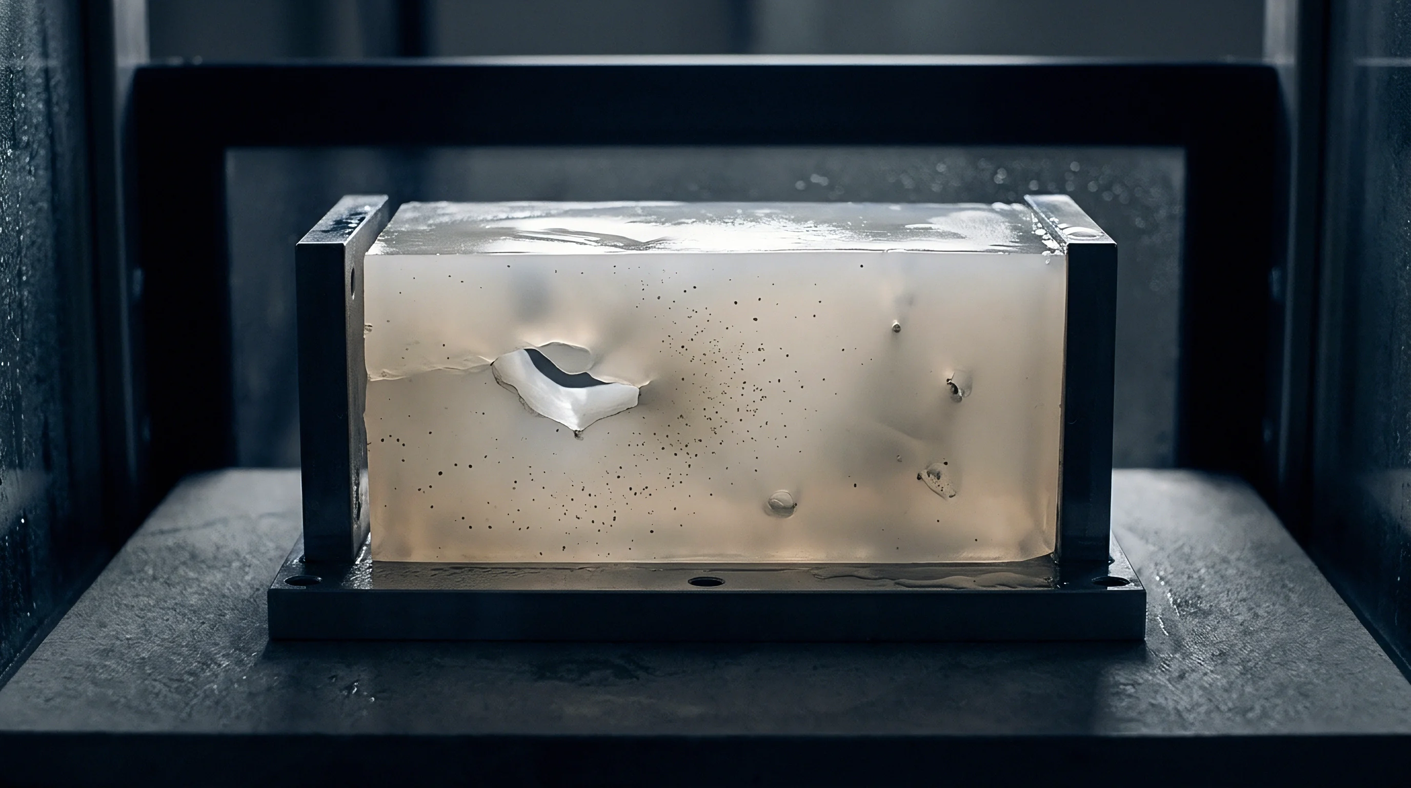
Optical birefringence links directly to anisotropic stress states resulting from flow-induced chain alignment. Three-dimensional viscoelastic solvers calculate stress tensor components by integrating constitutive equations along material streamlines during filling. Refractive index tensor variations emerge from these computed stress distributions via the photoelastic law, yielding predictions of optical retardation and fringe patterns in transparent molded parts.

Numerical Convergence in Variable Geometry Domains
Integrating non-linear viscoelastic constitutive models into full 3D transient thermal FEA solvers introduces steep computational penalties. High stress gradients near geometric corners or thin-to-thick step features cause solution instability if mesh refinement is inadequate. Convergence demands boundary layer meshing with element aspect ratios below five and a minimum of ten elements across the thickness profile.
| Solver Architecture | Element Type | Thickness Resolution | Thermal Stress Error Margin | Flow Stress Error Margin |
|---|---|---|---|---|
| 2.5D Midplane Shell | 3-Node Triangular Shell | 10 Equivalent Layers | 18 to 32 Percent | 25 to 45 Percent |
| 2.5D Surface Dual-Domain | 4-Node Surface Mesh | 12 Equivalent Layers | 15 to 28 Percent | 20 to 38 Percent |
| Full 3D Standard Solid | 4-Node Tetrahedral | 6 Solid Elements | 8 to 14 Percent | 12 to 22 Percent |
| Full 3D Layered Solid | 8-Node Hexahedral Prism | 14 Solid Elements | 2 to 5 Percent | 3 to 7 Percent |
The numerical worked calculation demonstrates this spatial resolution variance. Consider a 100-millimeter long step-plate cavity transitioning from 1.5 millimeters to 3.5 millimeters wall thickness over a 2-millimeter step distance. Under 2.5D midplane shell assumptions, calculated peak transverse stress at the step transition yields 8.4 megapascals.
Under a fully convergent 3D layered hexahedral mesh with viscoelastic integration, peak transverse stress reaches 21.6 megapascals. The three-dimensional representation captures localized out-of-plane shear gradients and thermal mass accumulation that midplane approximations obscure entirely. It remains uncertain how non-isothermal boundary layer slippage during high-speed injection alters the shear-induced stress distribution at the immediate mold wall boundary.

Probing
Physical validation of calculated viscoelastic stresses relies on empirical test methodologies. Non-destructive optical techniques measure stress-induced refractions in amorphous transparent polymers, providing full-field stress visual mapping. Destructive methods, such as incremental hole drilling or layer removal, quantify stress profiles through physical material relaxation measurements across opaque semi-crystalline parts.
Chemical exposure testing subjects molded components to specific solvent environments to identify critical residual tensile stress thresholds. Solvents accelerate micro-crazing and environmental stress cracking (ESC) in regions where surface tensile stress exceeds material-specific strain limits.
Birefringence Quantification and Optical Retardation Mapping
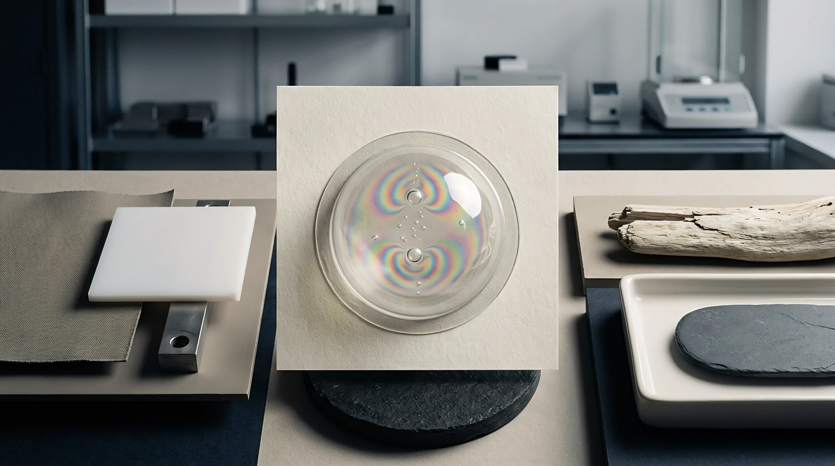
Polarized light transmission through transparent parts yields fringe patterns corresponding to principal stress differences. Quantitative photoelasticity converts phase retardation angles into principal stress values using the optical strain coefficient:
sigma_1 – sigma_2 = (N lambda) / (C d)
where N represents fringe order, lambda denotes light wavelength, C is the photoelastic constant, and d defines optical path length through the test specimen.
Hole Drilling Mechanics for In-Depth Stress Profiling
Incremental hole drilling involves attaching a high-precision strain gauge rosette to the part surface and drilling a shallow hole in discrete depth increments. Relaxed surface strains recorded at each depth step allow back-calculation of original residual stresses as a function of distance from the mold surface, validating numerical FEA prediction curves.
Solvent immersion testing reveals residual stress distribution through localized crazing before dimensional warping manifests on inspection fixtures.
- Mount the transparent test part between crossed polarizing filters angled at 45 degrees relative to the principal part axes.
- Illuminate the assembly with a monochromatic sodium light source operating at a calibrated 589-nanometer wavelength.
- Capture digital fringe pattern images using a high-resolution charge-coupled device sensor aligned perpendicular to the surface.
- Process optical phase shift data using monochromatic fringe-analysis software to yield two-dimensional principal stress maps.
Contractual clauses enforcing ASTM D1939 solvent immersion acceptance criteria define clear exposure time thresholds, preventing contentious liability disputes over chemical stress cracking in the field.
Tolerance
Tool design practices mitigate residual stress effects through calculated steel modifications and optimized cooling line placement. Compensating tool cavity geometry for anisotropic thermal shrinkage requires applying non-uniform shrink factors across variable wall features. Standard linear shrink factors fail when wall thickness shifts create localized differential stress states.
Precision tooling specifications reference international standard frameworks to define acceptable dimensional variances. DIN 16742 classifies molded part tolerances into specific tolerance groups (TG1 through TG8) based on material group, tool accuracy, and process stability.

Tool Steel Cavity Shrinkage Allowance Adjustment
Cutting tool steel using isotropic shrink estimates guarantees dimensional out-of-spec conditions on variable-wall components. High residual tensile stress causes post-ejection collapse across internal radii and feature corners. Modifying cavity geometry to offset predicted viscoelastic deflection ensures final part dimensions settle within specified tolerance bands after 24 hours of room-temperature conditioning.
| Tolerance Group (DIN 16742) | Application Grade | Permissible Dimensional Variance (50 mm Nom) | Max Surface Residual Stress (PC) | Max Surface Residual Stress (PA66) |
|---|---|---|---|---|
| TG3 | Precision High-Tolerance Tooling | +/- 0.08 mm | < 8.0 MPa | < 10.5 MPa |
| TG4 | Fine Engineering Components | +/- 0.12 mm | < 12.5 MPa | < 16.0 MPa |
| TG5 | Standard Commercial Parts | +/- 0.20 mm | < 18.0 MPa | < 22.5 MPa |
| TG6 | General Industrial Castings | +/- 0.35 mm | < 25.0 MPa | < 30.0 MPa |
Commercial Quality Agreements and Dimension Sign Off
Procurement documentation must explicitly link part acceptance to verified stress thresholds alongside dimensional compliance. A part measuring within nominal drawing dimensions immediately after ejection can warp out of tolerance four days later as unrelaxed core stresses dissipate. Quality clauses mandate conditioning parts at 23 degrees Celsius and 50 percent relative humidity for 48 hours prior to final CMM measurement sign-off.
- Specify 3D viscoelastic FEA stress simulation deliverables within early design sign-off milestones to validate wall transition radii before cutting steel.
- Incorporate conformal cooling channels in heavy cavity sections to equalize thermal extraction rates across variable wall features.
- Mandate DIN 16742 TG4 tolerance windows only when combined with verified internal stress limits below fifteen megapascals.
- Establish post-molding measurement hold periods of 48 hours to ensure viscoelastic relaxation completes prior to dimensional sign-off.
Tooling sign-off rests on combining precise steel geometry with controlled cooling performance. When thermal mass variations receive correct cooling channel layout and packing pressure profiles, parts meet strict dimensional criteria reliably across high-volume production shifts.