Tool Steel Modification Mechanics for Precision Injection Tooling
Precision tool steel modifications succeed by controlling thermal gradients during deposition and EDM to eliminate brittle white layers and residual stresses.

Alloy
Base tooling substrates determine the physical boundary conditions for any physical alteration performed on hardened injection moulds. Toolrooms modify precision cavities to correct dimensional shifts identified during first-article inspection, accommodate engineering change notices, or repair worn shut-offs. Premium tool steels respond disparately to localized thermal inputs, cutter forces, and electrical discharges.
In hardened martensitic tooling, the base matrix maintains a delicate balance between retained austenite, primary carbides, and secondary precipitates that shifts as soon as external energy enters the block.

Prehardened Tooling Substrates
Prehardened holder blocks and moderate-wear cavities built from DIN 1.2738 or AISI P20 supply a baseline hardness between 28 and 34 HRC. The carbon content in these grades stays below 0.40 percent, keeping carbon equivalency low enough to permit cold modifications without severe risk of catastrophic brittle cracking. Hardness remains uniform across thick cross-sections through deliberate balances of nickel and chromium additions, though localized mechanical cutting leaves compressive residual stresses extending up to 80 micrometers into the machined wall.
When deep machining removes extensive pockets, the release of bulk mill stresses induces macroscopic deflection across thin core shut-offs.

High Wear Martensitic Tool Steels
Through-hardened grades such as AISI H13 (DIN 1.2344) and AISI S7 provide the elevated compressive yield strengths between 1,400 and 1,650 MPa necessary to resist shut-off coining under fifty-tonne clamping pressures. These tool steels undergo vacuum austenitizing followed by pressurized gas quenching and multiple high-temperature tempering stages to reach working states of 48 to 54 HRC. Secondary hardening precipitates, predominantly vanadium and molybdenum carbides, dissolve only at temperatures exceeding 1,000 degrees Celsius.
When an alteration process locally heats an H13 core above the final tempering point of 550 degrees Celsius, over-tempering softens the substrate to 38 HRC, permanently destroying resistance to localized parting line indentation.
Hardened tool steels tempered above their secondary precipitation threshold experience permanent substrate softening that cannot be recovered through press-side adjustments.
Corrosion Resistant Martensitic Steels
Tooling intended for medical fluoropolymers, flame-retardant polyesters, and optical components relies on electroslag remelted stainless steels, primarily AISI 420 ESR (DIN 1.2083) and DIN 1.2085. The chromium concentration of twelve to fourteen percent generates a passive oxide layer that prevents hydrochloric or hydrofluoric acid pitting from off-gassing melts. Re-machining or heating 420 ESR triggers localized chromium carbide precipitation at grain boundaries if exposure dwells within the sensitization range of 450 to 600 degrees Celsius.
Local chromium depletion drops corrosion resistance below acceptable limits, causing visual cavity staining on Class A optical surfaces within ten thousand cycles of post-modification moulding.
| Steel Grade | Hardness Range (HRC) | Thermal Conductivity (W/m·K) | Tensile Yield Strength (MPa) | Critical Transformation Ac1 (°C) |
|---|---|---|---|---|
| AISI P20 (1.2738) | 28 to 34 | 33.5 | 830 | 780 |
| AISI H13 (1.2344) | 46 to 52 | 24.5 | 1,420 | 850 |
| AISI 420 ESR (1.2083) | 50 to 54 | 20.0 | 1,550 | 810 |
| AISI S7 | 54 to 58 | 28.0 | 1,680 | 825 |
| Maraging 300 (1.2709) | 50 to 56 | 21.0 | 1,900 | 650 |
Mouldmakers defending delivery schedules claim that minor surface adjustments on hardened blocks never compromise structural endurance because the core steel absorbs the balance of clamp loading.

Weld
Additive interventions deposit filler material directly onto worn shut-offs, undersized gates, or engineering change regions. The energy beam liquidates both the filler wire and a controlled boundary volume of the parent block, generating a molten pool that solidifies rapidly through conductive heat extraction into the massive mould base. This process creates a steep thermal gradient between the molten pool, the heat-affected zone, and the unaffected cold matrix.
Solidification cooling rates routinely exceed ten thousand degrees Celsius per second, transforming parent metal directly into untempered, high-carbon tetragonal martensite prone to instantaneous cracking.
Is Microstructure Matching Achievable across Laser Depositions?
Thermal input during pulsed Nd:YAG and fiber laser deposition remains concentrated within beam spots varying between 0.2 and 1.2 millimeters. The process introduces minimal total heat compared to conventional gas tungsten arc deposition, preserving geometric stability across adjacent precision ejector pin holes. The cooling rate forces carbon and alloying constituents to stay in supersaturated solid solution, yielding microhardness spikes as high as 62 HRC inside the fusion zone when using matching carbon-content filler wire.
Matching base metallurgy demands matching thermal expansion characteristics. Depositing high-speed tool steel wire on an H13 substrate generates differential contraction stresses upon cooling, peeling the deposit from the substrate along the fusion line during high-pressure injection packing.
Filler selection governs long-term tool performance across millions of injection cycles. Precipitation hardening iron-nickel maraging fillers containing cobalt, molybdenum, and titanium provide an effective solution for repairing hardened tooling. These fillers deposit as ductile nickel martensite exhibiting initial hardness near 32 HRC, eliminating the danger of cold cracking during cooling without extensive preheating of the tool block.
Subsequent thermal aging at 480 degrees Celsius triggers uniform precipitation of fine intermetallic phases, elevating hardness to 52 HRC while maintaining a tough, homogeneous boundary with the substrate.
- Preheating the tool insert raises the core block between 200 and 300 degrees Celsius to decrease conductive cooling rates and prevent untempered martensite shock.
- Laser spot overlap alignment maintains a seventy percent pitch across adjoining weld beads, preventing inter-pass cold laps and oxide inclusions.
- Protective shielding gas delivery supplies ninety-nine point nine nine percent pure argon at ten to twelve liters per minute through an angled nozzle to prevent surface nitriding.
- Immediate post-deposition tempering bakes the modified insert at fifty degrees Celsius below the original tempering point for two hours to relieve residual peak tensile stresses.

Micro-TIG Deposition Parameters
Coarse repairs requiring substantial volumetric build-up beyond the deposition rate of micro-laser systems turn to micro-TIG welding. Current settings between five and thirty amperes allow deposition of filler wire diameters ranging from 0.3 to 0.8 millimeters. Heat input per unit length remains four to eight times higher than laser processing, widening the heat-affected zone to more than two millimeters.
The parent material directly beneath the fusion line experiences partial austenitization, creating an unrefined coarse-grain structure with reduced impact toughness. If the mould setter operates the press with a clamping tonnage near machine capacity, thin shut-off lands modified via micro-TIG suffer micro-spalling and chipping along the fusion boundary within fifty thousand shots.
Deposition of filler wire without immediate multi-stage stress reduction guarantees brittle cleavage failure along the heat-affected boundary under cyclical press loading.
Neglecting localized preheating during laser wire addition on through-hardened martensitic stainless steels produces invisible micro-cleavage fractures that propagate through the cooling water jackets once the tool experiences sixty bar hydraulic injection pressures.

Cut
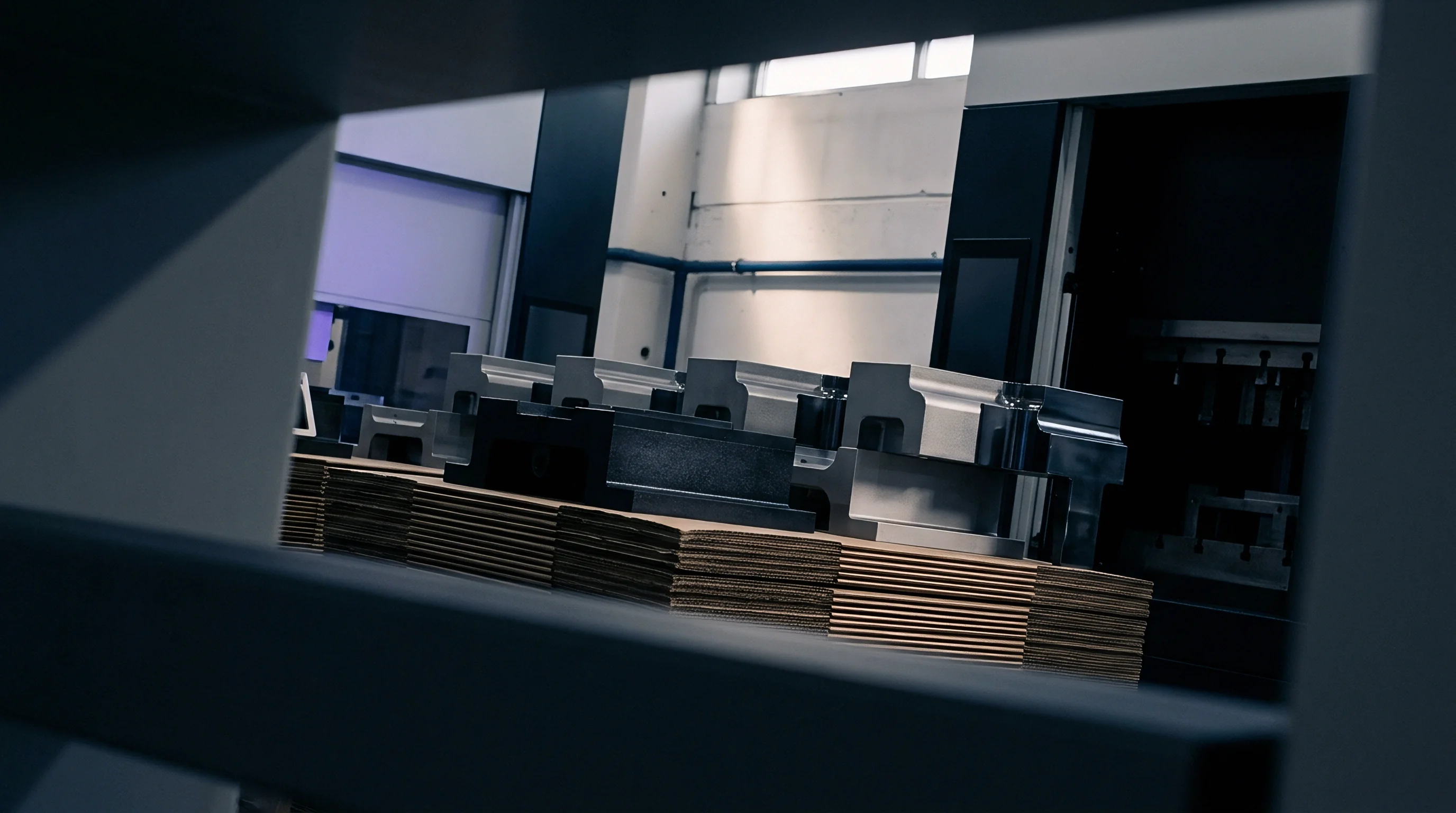
Subtractive steel removal operations shape altered contours and restore worn shut-offs to drawing specifications. High-speed hard milling of substrates at 54 HRC relies on solid carbide or cermet endmills with titanium silicon nitride coatings, cutting at surface speeds between 120 and 220 meters per minute. Tool deflection during hard milling introduces dimensional tapering across vertical ribs, pushing tight DIN 16742 plastic tolerances outside acceptance bands.
Feed rates per tooth remain below 0.04 millimeters to manage chip thickness and prevent micro-chipping of cutting edges, maintaining surface roughness values under 0.4 micrometers Ra.

Will Sinker Discharges Induce Subsurface Microcracks?
Electrical discharge machining vaporizes hardened tool steel using high-frequency dielectric spark discharges between a shaped graphite or copper electrode and the steel cavity. Each plasma spark melts a micro-crater while thermal conduction into the cold bulk material quenches the boundary liquid layer instantly. This mechanism leaves a recast surface, commonly designated as the white layer, composed of brittle re-solidified steel saturated with carbon cracked from hydrocarbon dielectric fluids.
The recast layer exhibits hardness values above 65 HRC and contains tensile stresses equivalent to the ultimate tensile strength of the substrate. Under the recast layer lies an over-tempered heat-affected zone exhibiting reduced yield strength and high vulnerability to fatigue failure.
| Machining Phase | Pulse Current (A) | Pulse Duration (μs) | Recast Layer Thickness (μm) | Microcrack Depth Max (μm) | Surface Finish (Ra μm) |
|---|---|---|---|---|---|
| Coarse Roughing | 24.0 | 120 | 28.5 | 45.0 | 6.30 |
| Medium Finishing | 6.5 | 45 | 8.2 | 14.0 | 2.10 |
| Fine Polishing Discharge | 1.2 | 8 | 2.1 | 3.5 | 0.65 |
| Micro-Spark Orbiting | 0.3 | 2 | 0.4 | 0.0 | 0.18 |
Wire EDM cutting presents identical white layer mechanisms on through-cavity insert pockets, slide ways, and ejector blade cutouts. Modern generator architectures mitigate recast depth by applying high-frequency anti-electrolysis AC pulse circuits that suppress carbon diffusion into the cutting boundary. Successive trim cuts, moving inward in stepped increments between four and eight passes, progressively consume the brittle white layer created during the primary roughing cut.
The final skim cuts lower the recast thickness to less than one micrometer, leaving a surface that accepts high-gloss optical diamond polishing without requiring aggressive manual stone benching.
When engineering changes demand removal of existing EDM surfaces, chemical etching and mechanical stone polishing clear the fractured crust before the mould returns to production. Residual electrical discharge layers left on the tool core become initiation sites for thermal fatigue cracking, also termed heat checking, during cycles where unfilled engineering polymers like polybutylene terephthalate or polyphenylene sulfide enter the cavity at 300 degrees Celsius melt temperatures. Manual polishing using cross-hatched diamond paste movements eliminates microcrack notches, maintaining uninterrupted mechanical contact between the mould steel and the polymer melt.
Tooling purchase agreements standardly incorporate ISO 10204 3.1 inspection certification mandates covering non-destructive surface magnetic particle testing to confirm zero surface crack presence following hard electrical machining operations.
Grain
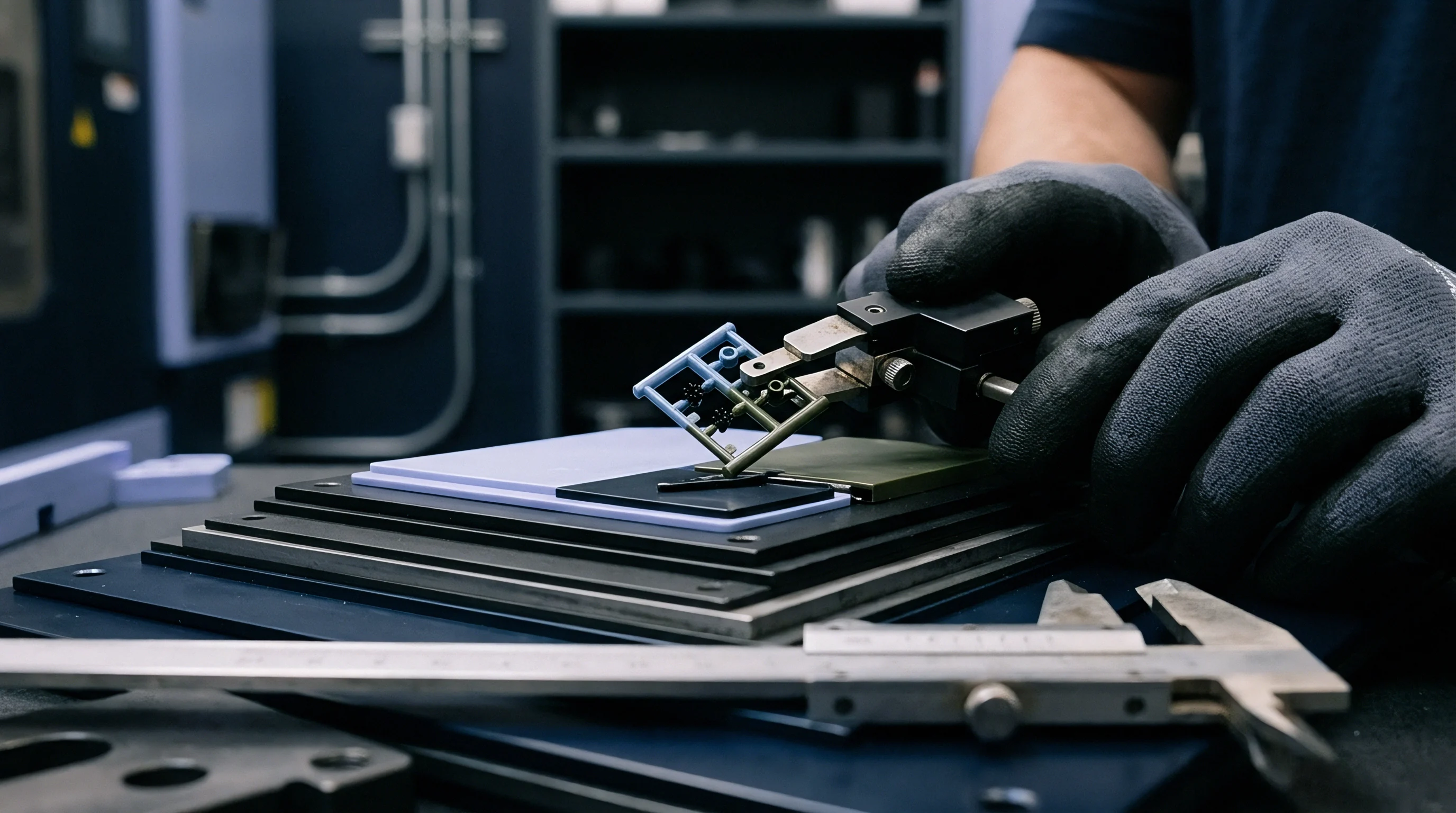
Microstructural evolution during localized tool steel re-working defines whether a modified injection tool survives high-volume manufacturing. When a tool block undergoes localized heat cycles from welding or coarse electrical discharging, grain boundary precipitation alters secondary carbide distributions across the atomic lattice. The metallurgical interface between the original base structure, the heat-affected zone, and the newly solidified modification creates sharp discontinuities in elastic modulus and thermal expansion behavior.
Under thermal cycling inside the injection press, these discontinuities concentrate interfacial shear stresses, driving premature parting-line delamination.
Residual Stress Evolution
Differential volumetric expansion drives internal stresses during rapid heating and cooling cycles. Steel expands by approximately 1.2 percent in volume when transforming from parent austenite into room-temperature martensite. Because the deep interior of the cold mould block mechanically constrains the hot surface modification zone, volumetric expansion cannot proceed freely.
High compressive stresses build during transformation, immediately reversing into massive surface tensile residual stresses when the heated region contracts against the colder base during final cooling. Residual tensile stresses exceeding 600 MPa sit locked within the first two hundred micrometers of the tool surface, directly beneath the modified zone.
Post-modification thermal processing relaxes internal stress concentrations to safeguard mechanical integrity. Sub-critical stress relief tempering holds the modified insert at a controlled temperature range between 500 and 530 degrees Celsius for one hour per 25 millimeters of steel cross-section, followed by quiescent cooling inside the furnace. This thermal treatment relieves up to eighty-five percent of locked residual stresses without softening the parent H13 or S7 microstructure below its designated 50 HRC threshold.
Controlled furnace cycles also encourage retained austenite within the weld fusion zone to transform predictably into tempered martensite, preventing unplanned dimensional drift during subsequent moulding operations.
- Chemical etching disparity reveals visible halo rings across textured mould surfaces where localized carbon redistribution alters the steel dissolution rate under nitric acid baths.
- Localized hardness variations cause differential tool wear and flash formation along parting lines as soft over-tempered zones sink faster than unheated parent metal.
- Interfacial stress rupture fractures delicate slide interlocks and core pins along the heat-affected boundary during continuous cyclic injection pressures.
- Optical polishing haze produces uneven reflectivity on lens cavities because hard secondary carbide clusters resist diamond compound abrasives differently than the surrounding softened matrix.
Grain Boundary Sensitization in Stainless Cavities
Modification of DIN 1.2083 stainless cavity inserts introduces severe risks of corrosion degradation when thermal cycles exceed 500 degrees Celsius. Carbon atoms diffuse rapidly toward austenite grain boundaries, binding with surrounding chromium to precipitate chromium carbide particles (Cr23C6). This metallurgical reaction strips chromium from the adjacent microstructural matrix, dropping the local dissolved chromium level below the twelve percent threshold needed to maintain chemical passivity.
When processing corrosive engineering resins such as plasticized PVC or flame-retarded polyamides, the depleted boundaries corrode along narrow intergranular paths, causing whole crystal grains to detach from the cavity surface and generating severe cosmetic drag marks on ejected components.
Why do certain vacuum stress-relieved inserts exhibit subtle dimensional movement across their primary shut-off faces three months into high-volume moulding runs while identical inserts run stable for millions of cycles?
Trial
Physical proof of modification success occurs only when the modified mould mounts into the injection press for rigorous process window qualification. Scientific moulding procedures decouple the injection stage into distinct filling, packing, and cooling phases, establishing objective data that verifies whether altered steel holds dimensions across extended production runs. Cavity pressure transducers positioned directly behind ejector pins or beneath gates quantify the transmission of hydrostatic pressure through the polymer melt.
Modifications that restrict gate flow or alter local runner diameters manifest as immediate drops in peak cavity pressure traces across affected impressions.
Dimensional Verification Workflow
Tool modifications alter the thermal equilibrium of the mould, changing localized shrinkage rates across the part geometry. Precision injection components demand strict adherence to dimensional tolerances governed by standards such as DIN 16742 or ISO 20457. A modified shut-off alters local cooling line proximity, creating uneven cavity surface temperatures that induce part warpage across flat mounting datum surfaces.
Statistical process verification tracks key critical-to-quality dimensions across consecutive production cycles to confirm process capability.
- Mount the modified mould base into the injection press, setting oil or water cooling circuits to specified temperatures verified via calibrated external thermocouple probes.
- Run sixty short-shot injection cycles without holding pressure to confirm balanced melt advancement across all cavity gates within a three percent weight variance.
- Conduct an eight-point packing pressure search to determine the exact gate seal freeze time using calibrated precision scales holding zero point zero zero one gram accuracy.
- Operate the machine under continuous automatic cycling for four hours to achieve steady-state thermal equilibrium across core and cavity inserts.
- Collect fifty consecutive shot samples across all cavities for coordinate measuring machine inspection against original engineering CAD models.
- Calculate capability indices across all drawing features, establishing whether process stability satisfies Cpk values exceeding one point six seven.
Dimensional stability of modified cavity steel can be verified only after the mould achieves uninterrupted thermal equilibrium at continuous cycle rate.
Cost calculations determine whether modifying an existing precision insert makes commercial sense compared to manufacturing a completely new insert from raw stock. Modification through precision laser welding and EDM re-cutting demands approximately thirty to forty-five percent of the direct capital expenditure of cutting new steel, while delivering a compressed lead time of three to five business days. The commercial risk profile flips when modifications sit in high-wear shut-off locations.
If an un-tempered laser repair breaks down after seventy thousand shots during an automotive production launch, the associated machine downtime, press reallocation penalties, and sorting costs surpass the cost of three complete spare inserts built fresh from virgin steel.
Careful toolmakers track every physical modification inside the official tool logbook because unrecorded steel changes permanently void supplier tooling warranties.