Standard ISO 25178 Parameters for Optical Profilometry Inspection
ISO 25178 areal optical profilometry replaces subjective 2D stylus traces with quantitative 3D parameters that accurately govern tool wear and part demoulding.


Field
Optical profilometry under ISO 25178-2 shifts surface evaluation from single line traces to non-contact 3D areal topographies. Standard linear measurements under older frameworks like ISO 4287 drag a diamond stylus over one path across a polished tool cavity or polymer molding. That single line easily skips over isolated pitting, directional scratches left by hand polishing, or melt-fracture marks in thin-walled parts.
Running a stylus once over a laser-etched cavity produces wild variations simply because where the line sits relative to individual micro-structures changes the height trace. Areal measurement samples an entire surface patch, capturing millions of height points across a fixed field of view at the same time.
Measuring across three dimensions gets rid of the positional bias built into single-line profiles. Optical instruments capture millions of points over a square or rectangular field using coherence scanning interferometry, chromatically aberrated confocal microscopy, or focus variation metrology. How light interacts with the sample’s shape sets the limits of spatial resolution.
The objective lens’s numerical aperture determines lateral resolution and caps the maximum measurable surface slope. Deep micro-fluidic channels or high-aspect-ratio ribs in molded cyclic olefin copolymer substrates scatter light away from the objective detector, leaving local dropout spots that require spatial filtering or mathematical reconstruction.
Areal spatial sampling runs on defined non-zero evaluation regions. Standard measurement areas usually range from 100 micrometers square for precision optical lens inserts to several square millimeters for textured automotive tooling. Choosing a field of view is a compromise between lateral pixel resolution and total scanned area.
A tight field resolves fine spatial details like the rims of single EDM craters, but needs spatial stitching to capture broad waviness over a large insert face. Enlarging the field brings macro-waviness into view, but risks spatial aliasing if fine tool marks drop below the sensor’s pixel pitch.
| Evaluation Domain | ISO 4287 Profile Metric | ISO 25178 Areal Metric | Physical Tooling Feature Quantified | Optical Metrology Limitation |
|---|---|---|---|---|
| Average Roughness | Ra (Arithmetical mean profile height) | Sa (Arithmetical mean areal height) | Overall surface amplitude across polished tool steel cavity | Averages peak and valley spikes, obscuring single micro-scratches |
| Root Mean Square | Rq (Root mean square profile height) | Sq (Root mean square areal height) | Statistical height variance of diamond-lapped SPI A-2 inserts | Sensitive to unmeasured spatial dropouts and optical speckle noise |
| Peak-to-Valley | Rt / Ry (Total height of profile) | Sz (Maximum height of areal surface) | Absolute extreme peak height to lowest pit depth over full patch | Highly susceptible to single-pixel optical spike artifacts |
| Skewness | Rsk (Profile asymmetry) | Ssk (Areal asymmetry) | Tooling wear state and plateau distribution of textured cavities | Requires robust S-F filtering to prevent tilt skewing data |
| Kurtosis | Rku (Profile sharpness) | Sku (Areal sharpness) | Presence of sharp machining burrs versus smooth plateau crests | Requires minimum sampling density of 100 points per peak radius |
Areal parameters surface features that single-line scans distort or flatten out. If a profile trace crosses a directional milling mark at forty-five degrees, it records a stretched, artificial wavelength that overstates the actual gap between cutter passes. 3D datasets preserve true orientation, tracking lay direction, surface anisotropy, and local volume distribution across the full patch.
Because the optical profilometer records the full spatial frequency spectrum, it provides the data needed to separate fine surface roughness from broader tool deformation or heat-treat warping.
Scanning optically avoids damaging soft copper EDM electrodes or delicate polymer replicas. A diamond stylus dragged over soft thermoplastics easily scratches optical PMMA light guides or gouges micro-structured medical chips. Optical tools inspect these surfaces without touching them, achieving sub-nanometer repeatability while leaving the polymer intact.
The light beam measures flexible materials, tacky elastomeric seals, and hot-runner tips without exerting any physical pressure that would alter the surface profile.
The chosen instrument establishes the physical transfer function of the inspection system. Coherence scanning interferometry delivers sub-nanometer vertical resolution regardless of magnification, which works well for mirror-polished optical inserts. Focus variation handles steep sidewall slopes up to eighty-five degrees on coarse laser-etched textures, but loses vertical resolution on smooth, highly reflective surfaces.
Chromatic confocal profiling sits between the two, rapidly scanning reflective metals and semi-transparent polymer moldings. Ultimately, the underlying optical method dictates how edge diffraction, interference effects, and local reflectivity show up in the raw data.
A common practical challenge is correlating optical profiles taken on a steel cavity directly with those measured on molded polymer parts. Differential thermal shrinkage as the polymer crystallizes alters both spatial wavelengths and height metrics relative to the tool. Furthermore, high-viscosity melts will not fully pack micro-textures if cavity pressure falls below a critical threshold, leaving an incomplete impression of the steel surface.
Pinpointing the exact threshold where optical metrics reliably mirror polymer replication fidelity across different mold temperatures remains an ongoing empirical effort.


Height
ISO 25178-2 height parameters evaluate how vertical z-axis coordinates are distributed across the areal region. They quantify amplitude alone, without accounting for spatial layout or horizontal patterns. The arithmetical mean height, Sa, measures the average absolute vertical distance of all data points from the mean surface plane.
While Sa is standard for basic quality checks, it says little about functional surface behavior. Two tool steel inserts with identical Sa values can look totally different: one might have scattered corrosion pits, while the other bears sharp peaks left by wire EDM.
Root mean square height, Sq, offers greater statistical sensitivity to amplitude variations across the field. By calculating the standard deviation of surface heights, Sq gives more weight to extreme peaks and valleys than Sa does. On SPI A-1 diamond-polished optical tooling, Sq assesses finish uniformity and highlights residual scratches from fine abrasives.
On nickel-plated mirror inserts for automotive headlamps, Sq must stay below four nanometers to prevent light scattering.

Extreme Amplitude Parameters and Spatial Spikes
Maximum peak height Sp measures the distance from the mean plane to the highest peak, while maximum pit depth Sv measures down to the lowest valley. Combining the two gives maximum height Sz ~ the overall peak-to-valley range. In optical profilometry, Sz requires close scrutiny: single-pixel noise or stray optical reflections can easily trigger false spikes that inflate Sz by orders of magnitude.
Statistical parameters describe how heights are distributed across the sample area. Skewness, Ssk, measures height asymmetry around the mean plane. A symmetrical profile, like ground steel, gives an Ssk near zero.
Negative skewness points to a plateaued surface with deep, fluid-retaining valleys ~ typical of a worn or plateau-honed mold. Positive skewness indicates protruding peaks, characteristic of freshly grit-blasted cavities or EDM surfaces covered in recast droplets.
Peak height distributions with positive skewness accelerate mechanical mold wear by concentrating interfacial contact stresses along narrow peak tips.
Kurtosis, Sku, measures the spikiness of the height distribution. An Sku of three indicates a Gaussian distribution. Values above three reflect a narrow, spiked distribution with sharp peaks or deep pits extending well beyond the main profile.
Values below three mean heights are concentrated in a broad, flat band. In injection mold tooling, an Sku well above three usually points to isolated machining burrs or embedded abrasives that need deburring or chemical cleaning before production.
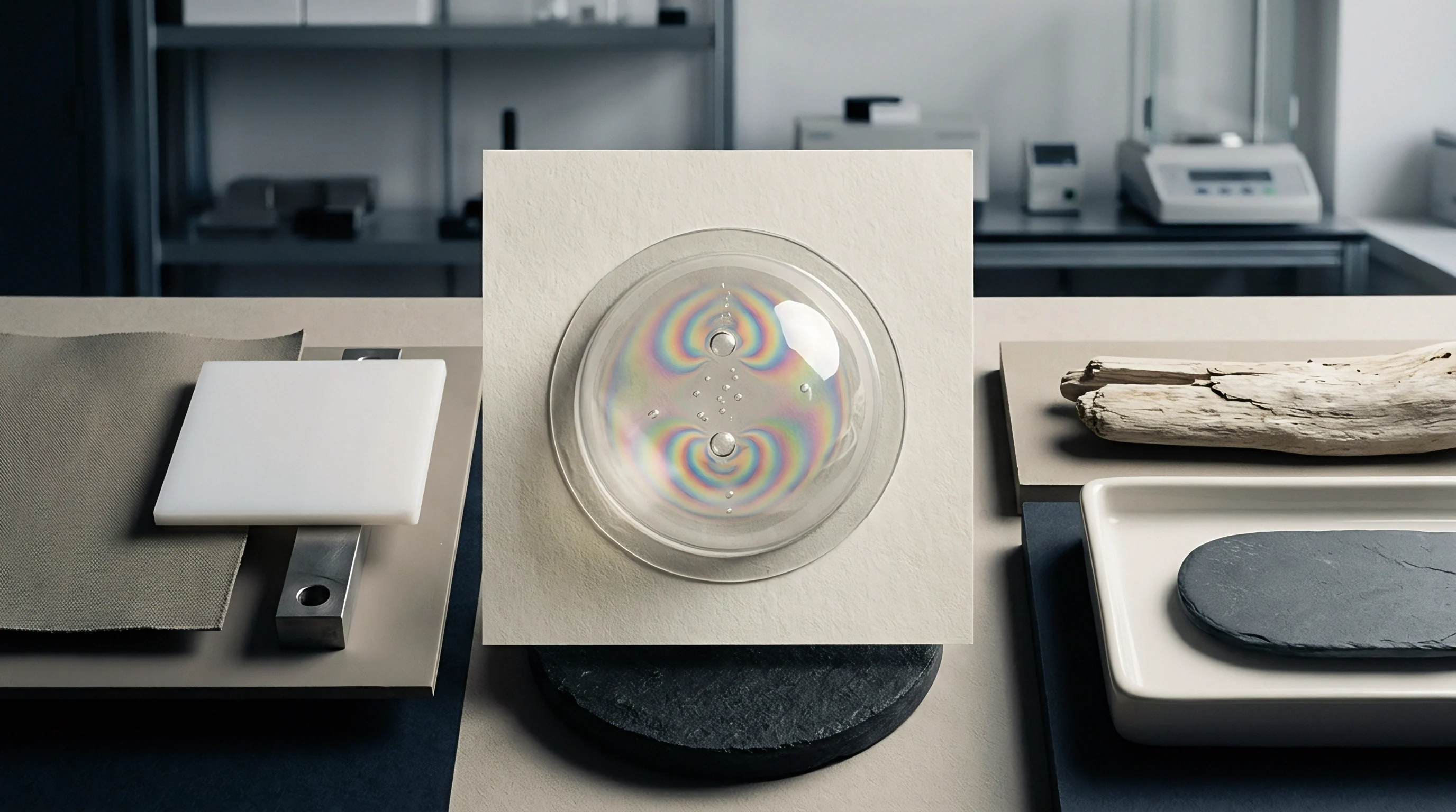
Surface Height Defect Modes in Molded Components
Evaluating molded polymer components with ISO 25178 height parameters helps identify defect modes caused by bad processing settings or tool wear. Distinct molding anomalies shift the height distribution in predictable ways.
- Recast Ridge Droplets form on spark-eroded tools when dielectric fluid fails to clear molten metal, resulting in high positive Ssk values that cause part tearing during ejection.
- Micro-Sink Impressions occur over internal ribs if packing pressure drops, pulling the z-axis downward locally to push Sq higher while reducing local Sku.
- Abrasive Drag Scratches happen during hand polishing with diamond paste, cutting narrow, deep valleys that elevate Sv and Sz without noticeably shifting the Sa baseline.
- Melt Fracture Ripples form on extruded films under high shear, creating fine, periodic height oscillations that raise both Sq and Sku.
Interpreting these parameters often requires looking at height probability density curves for specific finishes. For instance, textured molds for soft-touch automotive trim use controlled height distributions to achieve a target feel. Chemical etching creates a multi-tiered distribution where broad plateaus support fine secondary micro-textures.
Optical profilometers map these multi-modal curves by capturing the full histogram, giving engineers a way to track tool wear as repeated molding cycles gradually round off primary peaks.
The sub-nanometer vertical resolution of optical interferometry makes it possible to detect subtle thermal degradation on mold surfaces. Continuous heat cycling in high-volume production causes micro-cracking and grain boundary relief in tool steel. Height tracking reveals early micro-cracks ~ showing up as rising Sv values and negative Ssk shifts ~ long before cracks are visible under an optical microscope.
Catching steel degradation early allows planned re-polishing before cavities crack or cause unscheduled downtime.
Measuring semi-transparent or reflective polymers requires careful instrument setup. Materials like polycarbonate, transparent ABS, and acrylic allow light to penetrate slightly beneath the surface. This creates internal reflections off density changes or filler boundaries, generating phantom peaks that throw off Sa and Sq measurements.
Using polarized lighting, tweaking acquisition thresholds, or applying thin opaque coatings suppresses subsurface reflections so the instrument measures the actual outer surface.
As a practical rule of thumb, when Sz exceeds six times the Sa value on a finished mold insert, the surface likely has isolated structural defects rather than a uniform machining texture.


Spatial
ISO 25178-2 spatial parameters evaluate the horizontal layout, periodicity, and spatial frequency of features across the x-y plane. Height parameters like Sa and Sq record amplitude alone, completely ignoring layout; a surface with broad, gentle waves can yield the same Sa and Sq as one packed with dense, needle-like spikes. Spatial metrics quantify these lateral structures, providing vital data whenever surface orientation, directional friction, or light diffusion drives part performance.
Autocorrelation length, Sal, measures how far across the surface a texture remains self-similar. Mathematically, it is the shortest distance over which the normalized autocorrelation function falls to a set threshold ~ typically 0.2. A small Sal value means the surface is dominated by fine, high-frequency features, like those on fine grit-blasted steel or ceramic coatings.
A large Sal indicates a smooth surface with long spatial wavelengths, typical of fluid-polished inserts or diamond-turned lenses.
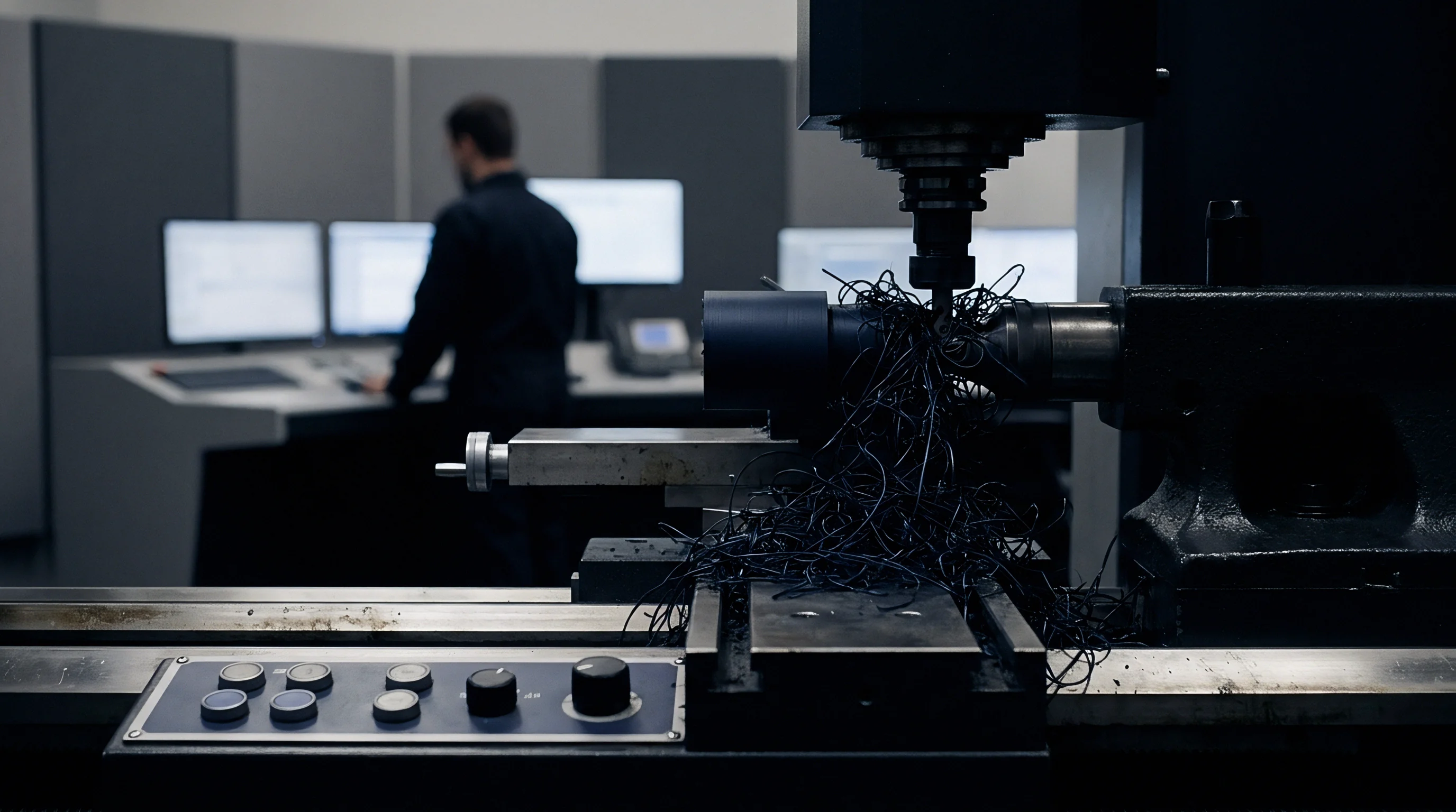
Texture Aspect Ratio and Directional Anisotropy
Texture aspect ratio, Str, measures surface isotropy. Derived from the ratio of the shortest to longest autocorrelation decay distances, Str yields a dimensionless number between zero and one. Values near one indicate an isotropic surface with identical properties in all directions, like bead-blasted cavities or unaligned chemical textures.
Values below 0.1 mark a strongly directional, anisotropic surface, such as parallel tool marks from face milling, grinding, or single-point diamond turning.
Quantifying anisotropy with Str offers practical guidance during mold design and ejection evaluation. Thermoplastic parts ejected from cavities with directional tool marks aligned parallel to the draw experience less friction during ejection. Conversely, machining marks running perpendicular to the ejection stroke act like tiny mechanical locks, boosting ejection forces, scuffing sidewalls, and wearing out ejector pins.
Measuring Str on deep sidewalls confirms that polishing cleared transverse tool marks before releasing the mold for production.
Texture direction, Std, identifies the primary orientation of anisotropic features relative to a reference axis. Calculated from the angular power spectrum of the dataset, Std gives the dominant angle of parallel machining or grinding marks in degrees. On multi-axis CNC milled inserts, tracking Std confirms that toolpaths align across complex parting lines, eliminating visible texture seams on cosmetic parts.

Worked Example: Spatial Parameter Evaluation of Laser-Etched Tool Surfaces
Consider a toolroom evaluating a hardened H13 core insert for an automotive instrument panel. The design calls for a uniform, low-glare matte finish with complete spatial isotropy to prevent directional reflections in sunlight. The mold shop tests two finishing approaches: Method A uses conventional EDM with a fine copper electrode, while Method B uses five-axis picosecond laser ablation to cut a randomized micro-pattern.
Optical profilometry inspection of both test patches across a two-millimeter square evaluation field yields the following measured spatial dataset:
| Finishing Process | Autocorrelation Length Sal (µm) | Aspect Ratio Str (Dimensionless) | Dominant Direction Std (Degrees) | Topographical Classification |
|---|---|---|---|---|
| Method A: Fine EDM | 42.5 | 0.78 | 88.4 / 2.1 (Dual weak modes) | Predominantly Isotropic with minor electrode scan bias |
| Method B: Laser Etch | 18.2 | 0.94 | No dominant angle detected | Fully Isotropic micro-structure |
| Target Specification | < 25.0 | > 0.85 | None permitted | Isotropic low-glare requirement |
The dataset shows that Method A fails spatial requirements despite hitting an acceptable Sa of 1.2 micrometers. An Sal of 42.5 micrometers indicates spark craters that are too coarse, while an Str of 0.78 reveals directional scan lines left by the CNC electrode path. Method B hits every target: an Sal of 18.2 micrometers confirms a tight, high-frequency micro-texture, and an Str of 0.94 proves full spatial isotropy.
Choosing Method B eliminates directional glare on the molded dashboard without requiring expensive tool rework after trial runs.
An unverified milling lay on a deep-draw polypropylene housing caused part sticking and automated robot pick-and-place drops during high-speed production trials, incurring a forty-thousand-dollar tooling modification charge.
Decomposing spatial frequencies with fast Fourier transforms helps isolate periodic machining errors. Spindle chatter in CNC mills leaves periodic ripples across cut steel, creating distinct peaks in the power spectral density map. Optical profilometers extract these periodic signals, letting machinists catch worn spindle bearings or bad feed rates long before parts fail dimensional checks.


Hybrid
Hybrid parameters merge spatial and amplitude features across the 3D surface, evaluating slope, slope distribution, and developed surface area. Where height metrics measure vertical distances alone and spatial metrics look only at horizontal layouts, hybrid parameters combine both to measure gradients and structural complexity. These metrics offer clear insight into contact mechanics, liquid wetting, micro-fluidic resistance, and light refraction on molded parts and tool cavity walls.
Root mean square slope, Sdq, measures the average local surface tilt across all points in the evaluation area. Expressed in degrees or as a gradient ratio, Sdq quantifies surface steepness. A flat plane gives an Sdq of zero, while high values point to steep local slopes ~ typical of micro-prisms, sharp grit-blasted steel, or coarse EDM crater edges.
Sdq directly influences mechanical friction and seal performance: steeper local slopes raise contact stresses on peak tips, accelerating wear on moving tool components like slides, cores, and lifters.

Developed Interfacial Area Ratio and Surface Complexity
Developed interfacial area ratio, Sdr, measures the percentage of extra surface area created by texture compared to a flat plane of the same dimensions. A flat surface has an Sdr of zero percent. Dense micro-textures, sharp valleys, or micro-grooves push Sdr anywhere from a few percent to several hundred percent.
By quantifying true surface contact area, Sdr serves as a primary metric for chemical bonding, paint adhesion, plating mechanical locks, and laser welding in molded components.
In medical micro-fluidics, tracking Sdr ensures precise control over channel surface energy and capillary flow rates. Transparent cyclic olefin copolymer chips need channel surfaces within strict Sdr bounds to keep fluid movement predictable without trapping tiny air bubbles against the walls. Optical profilometers measure Sdr inside micro-channels to confirm laser ablation or micro-milling expanded the surface area without generating high-Sdq spikes that distort laminar flow.
| Functional Volume Metric | Symbol & Definition | Target Range (Tool Steel) | Functional Performance Impact |
|---|---|---|---|
| Peak Material Volume | Vmp (Volume of material in top 10% height) | 0.02 – 0.08 µm³/µm² | Controls initial mechanical run-in wear rate of mold core faces |
| Core Material Volume | Vmc (Volume of material between 10% and 80%) | 0.50 – 1.80 µm³/µm² | Determines primary structural load-bearing capacity of mating tool faces |
| Core Void Volume | Vvc (Volume of space between 10% and 80% depth) | 0.60 – 2.20 µm³/µm² | Dictates liquid lubricant retention capability along sliding lifter tracks |
| Dale Void Volume | Vvv (Volume of space in bottom 20% valley depth) | 0.05 – 0.25 µm³/µm² | Traps microscopic debris particles to prevent interfacial surface scoring |
Functional volume parameters are derived from the Abbott-Firestone material ratio curve to measure the physical volume of material or void space within specific height zones. Under ISO 25178-2, these metrics separate the surface into peak, core, and valley regimes using material ratio thresholds. Peak material volume, Vmp, measures the solid material volume in the top ten percent of the height distribution.
Core material volume, Vmc, isolates the material between the ten and eighty percent material ratio thresholds ~ the main load-bearing zone of the surface.
Void volume metrics quantify fluid storage and retention across the surface. Core void volume, Vvc, measures void space within the core zone, indicating how much lubricant sliding tool components can hold. Dale void volume, Vvv, measures deep valley voids in the lowest twenty percent of the height profile.
For elastomeric seals and high-pressure gaskets, specifying a minimum Vvv on cavity surfaces creates controlled micro-reservoirs on molded seals, preventing high-pressure leaks across mating surfaces in service.
Material ratio curves establish that surfaces with high core void volumes maintain reliable hydrodynamic lubrication film thickness under heavy mechanical clamping loads.
Linking hybrid parameters to tool life requires evaluating peak radius distributions alongside Sdq gradients. High Sdq values paired with low Vmc values indicate fragile peak tips that collapse under clamping pressure, causing flash along parting lines. Process engineers use these hybrid metrics to qualify new inserts, setting baseline complexity targets before approving multi-cavity molds for full-scale production.
In one polishing failure, the cavity hit the target average roughness spec yet retained steep local slopes that prevented clean part ejection.


Filtering
ISO 25178-3 filtering provides the mathematical workflow needed to break raw optical profilometer data into standardized, scale-specific topography layers. Raw scans mix multiple spatial frequencies, from overall part tilt and fixture flex down to fine optical noise and micro-roughness. Without standardized filters, parameters shift wildly based on field of view, instrument tilt, or pixel density.
ISO 25178-3 defines a unified framework of nested operators to separate form, waviness, and roughness.
The standard sets three main filter operators designated by letter codes. The S-filter acts as a low-pass filter, removing spatial features smaller than a set cutoff wavelength to eliminate optical noise, detector jitter, and lateral aliasing. The L-filter serves as a high-pass filter, stripping away long spatial wavelengths above a cutoff limit to remove macro curvature, tilt, and overall form error.
The F-operator subtracts nominal geometric shape ~ like cylindrical or spherical curves ~ by fitting a theoretical surface to raw data using least-squares algorithms.

Filter Selection and Cutoff Wavelength Rules
Choosing filter cutoff wavelengths requires matching the physical scale of the surface features being evaluated. Standard nesting indexes define these filtering boundaries. For typical injection mold cavity checks, the S-filter cutoff is often set at 2.5 micrometers, and the L-filter cutoff at 0.8 millimeters.
Applying an S-F operator removes form tilt while retaining roughness features above the S-filter cutoff, generating an S-F surface used to evaluate baseline Sa and Sq metrics.
An S-L filter combination isolates primary roughness, producing an S-L surface free of both form curvature and high-frequency noise. Setting the L-filter cutoff too low allows long-wavelength waviness to spill into roughness calculations, artificially boosting Sa and Sq. Setting it too high cuts off real roughness structures, generating overly optimistic finish reports that hide actual tool flaws.

Which Optical Profilometer Technology Fits Tooling Steel Texture?
Choosing the right optical measurement tech depends directly on surface roughness amplitude, spatial frequency range, and sample reflectivity. Coherence scanning interferometry provides sub-nanometer vertical resolution on smooth mirror finishes, but struggles on high-slope rough surfaces. Chromatic confocal microscopy handles steep angles and changing material reflectivity well, though lateral scanning is slower.
Focus variation rapidly maps steep macro-geometry on coarse grit-blasted textures, but lacks the vertical resolution needed for SPI A-1 mirror finishes. Matching hardware to the surface ensures strong signal-to-noise ratios before applying ISO 25178 filters.
Raw optical scans often contain unmeasured points caused by steep slopes, low local reflectivity, or optical shadows. ISO 25178-3 specifies exact interpolation rules for unmeasured points before spatial filtering. Isolated single-pixel dropouts are interpolated from surrounding valid pixels.
But if dropouts form clusters covering more than one percent of the evaluation area, the scan must be rejected, requiring the operator to adjust lighting, gain, or sample tilt and rescan.
- Mount the steel insert on a precision tilt stage, aligning the optical axis perpendicular to the nominal reference plane.
- Choose an objective lens with a numerical aperture high enough to capture the steepest expected surface slopes.
- Run a light intensity calibration, setting detector exposure to avoid pixel saturation on reflective peaks.
- Acquire the raw 3D height dataset across the full specified field of view.
- Apply the F-operator to remove tilt and nominal shape using polynomial least-squares fitting.
- Apply an S-filter low-pass cutoff at 2.5 micrometers to eliminate high-frequency speckle noise.
- Apply an L-filter high-pass cutoff at 0.8 millimeters to strip long-wavelength structural waviness.
- Extract normalized ISO 25178 height, spatial, and hybrid parameters from the prepared S-L surface dataset.
Gaussian regression filters defined in ISO 16610-28 resolve edge distortion artifacts commonly associated with traditional linear Gaussian filters. Standard linear filters distort surface height data near the boundaries of the optical field of view, forcing inspectors to discard a broad border around the perimeter of every scan. Gaussian regression filters maintain mathematical accuracy right up to the evaluation area edge, maximizing usable surface data when inspecting narrow tool ribs, micro-fluidic channels, or small optical mold inserts.
ISO 25178-3 mandates that every reported areal parameter must explicitly state the filter type, nesting indexes, and spatial bandwidth used during data extraction.
A lens’s physical optical transfer function introduces filtering before software processing even begins. The objective’s finite numerical aperture acts as a low-pass filter, attenuating frequencies above its diffraction limit. Quality protocols require calibrating optical profilometers against traceable step-height standards to confirm that the physical optical transfer function matches software filter assumptions across the full measurement bandwidth.
Under ISO 25178-3 clause 6.4, surface parameters reported without stating exact S-filter and L-filter cutoffs carry no contractual weight during quality disputes.

Checkout
Establishing formal checkout protocols for optical profilometry data ensures that toolroom specs translate into reproducible, binding inspection results. Procurement teams buying high-precision injection molds or optical-grade components need unambiguous surface requirements on drawings and purchase agreements. Vague callouts like “Polish to SPI A-2” trigger supplier disputes, because manual lapping produces variable topographies that look good visually while failing optical performance metrics.
A tight procurement specification replaces generic industry descriptors with explicit ISO 25178 parameter ranges, complete with filter settings and scan conditions. The contract documentation should specify the profiling tech, objective magnification, numerical aperture, field of view, S-filter and L-filter cutoffs, and dropout limits. Defining these terms upfront removes ambiguity so incoming inspection at the buyer’s plant mirrors supplier sign-off reports.
- Optical Setup Verification mandates documenting lens magnification, numerical aperture, and lighting modes used for data capture.
- Filter Bandwidth Compliance requires specifying S-filter and L-filter spatial cutoffs on all inspection drawings.
- Data Integrity Thresholds sets a strict 0.5 percent cap on allowable unmeasured data dropouts per scan.
- Traceable Standard Calibration calls for regular z-axis accuracy checks using NIST-traceable step height artifacts.
- Environmental Noise Isolation requires mounting profilometers on active vibration isolation tables inside temperature-controlled labs.
Integrating ISO 25178 parameters into tool acceptance trials streamlines sign-off and speeds up first-article approvals. Scanning representative cavities in multi-cavity molds highlights differences in CNC toolpaths, spark erosion generator drift, or manual polishing variations. Spotting cavity-to-cavity texture variations during initial T1 trials prevents finish defects and non-conformance during production ramp-up.
| SPI Finish Grade | Primary Machining / Polishing Process | Target Sa Range (µm) | Maximum Sz Limit (µm) | Mandatory Hybrid Parameter Target |
|---|---|---|---|---|
| SPI A-1 | Grade #3 Diamond Buffing Compound | 0.005 – 0.012 | 0.080 | Sdr < 0.05%; Sdq < 0.20° |
| SPI A-2 | Grade #6 Diamond Buffing Compound | 0.015 – 0.025 | 0.150 | Sdr < 0.10%; Sdq < 0.40° |
| SPI B-1 | 600-Grit Paper Polishing Pass | 0.040 – 0.080 | 0.500 | Str < 0.20 (Directional lay preserved) |
| SPI C-1 | 600-Grit Stone Polishing Pass | 0.100 – 0.200 | 1.200 | Ssk within -0.5 to +0.5 range |
| SPI D-1 | #11 Dry Oxide Blast Finish | 0.400 – 0.800 | 5.000 | Str > 0.80 (Fully isotropic surface) |
Quantifying surface topography with standardized 3D metrics gives buyers and suppliers clear data to resolve quality disputes. If molded parts show heavy ejection scuffing despite hitting drawing dimensions, profiling cavity sidewalls quickly points to the root cause ~ whether it is high peak sharpness Sku, transverse machining lay Std, or inadequate draft angles. Replacing subjective visual checks with objective optical profiling provides mathematical evidence that binds both parties to verifiable standards.
Documented optical inspection dossiers containing complete ISO 25178 parameter sets shorten tooling transfer validation cycles when shifting production molds between contract manufacturers.
Advanced optical profilometry protocols form the foundation for digital twin initiatives and automated tool-life management. Tracking shifts in height distributions, autocorrelation lengths, and material volumes across production runs lets maintenance teams schedule re-polishing before wear degrades part quality. Monitoring hardened steel inserts with routine profiling keeps process windows tight, protecting capital investments and ensuring uniform quality across multi-million-shot runs.
Implementing these optical metrology standards enforces supplier accountability across global supply chains. Quality engineers review digital inspection dossiers before releasing final tooling payments, confirming that steel surfaces meet specified areal parameter windows. Establishing clear optical profiling criteria ensures that replacement core inserts, spare cavities, and duplicate molds perform identically across different manufacturing sites.