Real Time Piezoelectric Waveform Phase Matching under Transient Cavity Thermal Gradients
Dynamic thermal filtering of piezoelectric cavity pressure waveforms eliminates thermal shock drift to synchronize multi-cavity switchover within sub-millisecond tolerances.
Quartz
Piezoelectric pressure transducers mounted flush in injection mould cavities register dynamic pressure waveforms through the direct piezoelectric effect of crystalline alpha-quartz. The mechanical stress applied across the sensor diaphragm displaces silicon and oxygen ions within the non-centrosymmetric trigonal lattice, generating an electrical charge proportional to normal force. In ultra-precision moulding of optical light guides and high-density electrical connectors, process engineers rely on this charge signal to trigger automatic switchover from velocity-controlled cavity filling to pressure-controlled packing.
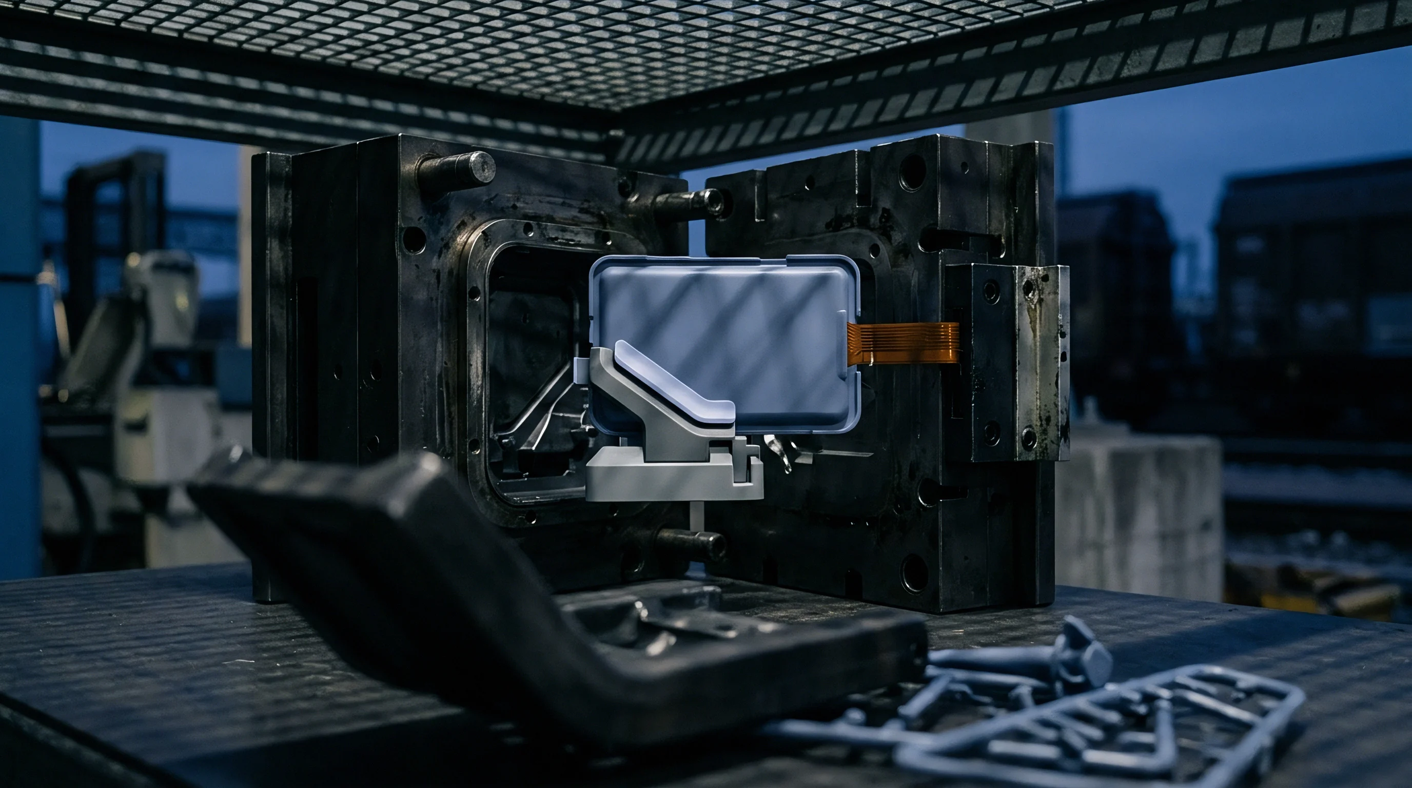
When the molten polymer front makes physical contact with the exposed transducer face, a sudden thermal shock occurs. Melt temperatures between 240 and 320 degrees Celsius strike a sensor body maintained at mould steel temperatures between 40 and 110 degrees Celsius. This sudden contact establishes a localized transient thermal gradient across the diaphragm within twelve milliseconds.
Quartz exhibits anisotropic thermal expansion alongside an intrinsic pyroelectric response along polar crystallographic axes. Unequal thermal dilation between the pre-stressed diaphragm, the internal quartz disc stack, and the tool steel housing induces parasitic mechanical strains that register as false pressure changes on charge amplifier circuits. Transducer manufacturers apply artificial compensation schemes or cut quartz crystals along specific crystallographic angles, such as the transverse orientation, to suppress spontaneous pyroelectric polarization.
Even with transverse crystal cuts, rapid conduction across the diaphragm rim produces bending moments that mimic pressure rise prior to genuine hydraulic pressurization of the cavity.
Thermal contact shocks above eighty degrees Celsius per millisecond distort quartz sensor charge accumulation before melt pressure rises.
Phase matching requires tracking the precise temporal arrival of characteristic waveform landmarks across multi-cavity tools. The primary landmark is the compression knee, where the filling curve transitions from ambient atmospheric venting resistance to melt pool compression. Transient thermal gradients introduce an artificial advance in the apparent arrival time of this knee.
A charge output spike induced by thermal strain arrives between 1.5 and 4.2 milliseconds before the physical polymer melt front reaches mechanical equilibrium across the sensor surface. Real-time control algorithms monitoring threshold voltage values execute switchover prematurely when reading this thermally contaminated landmark.
Signal corruption propagates directly into hydraulic valve timing. Premature switchover leaves flow fronts starved of filling velocity, precipitating non-uniform frozen layer development and flash-inducing pressure surges during secondary pack stages. The tool records hesitation marks on optical surfaces, localized sink marks near rib bases, and dimensional variance that throws critical connector pin pitches outside ISO 2768-m tolerances.
Scrap rates climb steadily during the first two hours of production runs while mould steel approaches thermal quasi-steady state.
Gradient
Cavity temperature fields during rapid injection cycles remain intensely transient. Heat transfer across the steel-polymer interface is dominated by contact resistance, boundary layer development, and coolant flow turbulence. Coolant passages drilled into P20 or H13 tool steel maintain bulk cavity temperatures, but the boundary layer between the frozen polymer skin and the mould wall experiences temperature swings exceeding 150 degrees Celsius within a single seventy-millisecond injection stroke.
Transducers placed near the gate experience sustained thermal exposure, whereas transducers positioned at the flow path extremity remain cold until the final ten percent of the filling cycle.
Melt Contact Mechanics and Charge Drift
The rate of heat transfer into the transducer housing governs the magnitude of charge drift. Fourier conduction across the sensor diaphragm produces a steep temperature profile through the quartz crystal thickness. The piezomagnetic and piezoelectric coefficients of quartz decrease as temperature increases toward the alpha-to-beta inversion point at 573 degrees Celsius.
Within standard operational envelopes between 20 and 200 degrees Celsius, the longitudinal piezoelectric sensitivity coefficient d11 declines at an average rate of 0.016 percent per Kelvin. A local temperature jump of 120 degrees Celsius across the sensor face reduces effective charge sensitivity by nearly two percent while simultaneously generating positive thermal strain charges.
Tool builders often place cooling lines unevenly to clear ejector pins and core pulls. Cooling asymmetry induces severe lateral temperature gradients across individual transducer housings. Differential thermal expansion tilts the transducer membrane, altering preload distribution on internal crystal elements.
| Parameter | Alpha-Quartz Single Crystal | Gallium Phosphate Single Crystal | DIN 1.2343 Housing Steel |
|---|---|---|---|
| Thermal Conductivity (W/m·K) | 6.8 to 11.2 | 2.1 to 3.5 | 28.5 to 30.5 |
| Thermal Expansion Coefficient (10⁻⁶/K) | 7.5 to 13.7 | 4.2 to 8.6 | 11.8 to 12.4 |
| Curie or Phase Transition Temp (°C) | 573 | 970 | N/A |
| Piezoelectric Modulus d11 (pC/N) | 2.31 | 4.50 | 0.00 |
| Temperature Drift of d11 (%/K) | -0.016 | -0.002 | N/A |
Charge amplifiers integrate all current generated across the piezoelectric element, unable to separate load-induced charges from thermally generated currents. Drift compensation circuits using passive resistor-capacitor leakage networks discharge steady-state bias, but cannot react to high-frequency thermal transients. Digital signal processors must estimate the transient thermal profile in real time to correct raw voltage curves.
Machine suppliers frequently dismiss these early signal distortions as simple baseline electronic noise that plant setters should ignore through delayed sensor activation windows.

Phase
Phase matching across multi-cavity tooling synchronizes injection profile adjustments to ensure simultaneous filling and packing across all impressions. Multi-cavity systems running engineered resins like polyether ether ketone or liquid crystal polymer depend on synchronous melt front arrival. When runner balance suffers from thermal gradients across the manifold, melt reaches cavity gates at staggered times.
Real-time control loops inspect pressure rise waveforms from cavity sensors to dynamically trim individual runner choke pins or balance hot-runner nozzle tips. Phase errors between transducers break this regulation mechanism entirely.
Waveform Landmark Extraction under Drift
Waveform alignment relies on detecting three specific temporal points during each injection cycle. The first derivative of the cavity pressure curve, designated dP/dt, marks the physical boundary conditions of cavity filling.
- Flow front impingement occurs when dP/dt exceeds a defined threshold, typically 0.5 bar per millisecond, signalling polymer contact with the transducer face.
- Volumetric cavity fill manifests as an inflection point where dP/dt reaches its primary maximum, marking the boundary between unconfined flow and cavity wall constraint.
- Hydrostatic pressurization peak appears when screw forward movement transfers force directly through the solidified runner core into the packed cavity.
Transient thermal gradients distort the extracted timing of these points. Thermal shock creates a positive artificial slope on dP/dt before flow front impingement occurs, leading the supervisory controller to register an early contact event. In hot-runner tooling running liquid crystal polymers with fill times below 0.15 seconds, a two-millisecond phase detection error represents more than one percent of total cycle fill duration.
A two-millisecond phase tracking error in thin-wall moulding causes severe cavity imbalance and short shots.
Phase synchronization algorithms eliminate these distortions by combining high-speed analog-to-digital conversion with digital finite impulse response filtering. Sensor signals sampled at 100 kilohertz pass through an inverse thermal filter model. This model approximates the thermal transfer function of the diaphragm using a dual-pole, single-zero state-space estimator calibrated to cavity wall thermocouple readings.
The estimator subtracts calculated pyroelectric and thermal-bending charges from raw amplifier output. Corrected waveforms are cross-correlated against an empirical master template to establish true phase alignment across eight, sixteen, or thirty-two cavities.
The standard procurement agreement under DIN 16742 Group 4 specifies that cavity balance must maintain part mass variation within plus or minus 0.3 percent across all tool cavities, an operational ceiling that cannot be verified without thermal compensation applied to sensor trigger points.

Circuit
Implementation of real-time phase compensation requires dedicated signal-processing hardware positioned directly beside the moulding press. Standard machine programmable logic controllers execute ladder scans with cycle times between one and ten milliseconds, which is too slow for transient phase compensation. Field-programmable gate arrays and dedicated digital signal processing boards process multi-channel piezoelectric signals at deterministic clock rates, calculating inverse thermal models within microsecond windows.

Worked Calculation of Thermal Gradient Phase Correction
Evaluate an eight-cavity injection mould producing polycarbonate optical lenses with a nominal wall thickness of 1.20 millimetres. The injection phase lasts exactly 350 milliseconds. Cavity pressure reaches 600 bar at switchover.
Each cavity contains a piezoelectric transducer with a nominal sensitivity of -2.50 picocoulombs per bar and a diaphragm area of 12.5 square millimetres.
During injection, melt enters Cavity 1 at 295 degrees Celsius while the transducer diaphragm sits at 85 degrees Celsius. Convective heat flux creates a transient temperature rise across the diaphragm outer face of 65 degrees Celsius within 15 milliseconds. The diaphragm thermal shock coefficient produces a parasitic charge generation rate of 0.42 picocoulombs per degree Celsius.
Uncorrected charge generation reaches 27.3 picocoulombs, equivalent to a false pressure reading of 10.92 bar.
Raw dP/dt thresholds trigger at 5.0 bar to initiate phase synchronization timing. The uncorrected sensor signals trigger the threshold 4.8 milliseconds ahead of true melt arrival. Across the eight cavities, uneven hot-runner manifold temperatures cause temperature differentials of up to 18 degrees Celsius between cavity gates.
Cavities 1 through 4 trigger false fill landmarks between 3.6 and 4.8 milliseconds early, while Cavities 5 through 8 trigger between 1.8 and 2.9 milliseconds early. Uncompensated controllers interpret this 2.0 to 3.0 millisecond spread as structural flow imbalance, erroneously commanding valve gates to throttle flow in the first four cavities.
Real-time compensation hardware applies the discrete compensation algorithm. The circuit reads high-speed co-located thermocouple voltages alongside piezoelectric charge inputs. It executes the discrete state calculation:
q_corrected(k) = q_raw(k) – K_th (T_diaphragm(k) – T_bulk) (1 – exp(-k delta_t / tau_th))
Setting calibration gain K_th to 0.42 picocoulombs per Kelvin and the thermal time constant tau_th to 8.2 milliseconds restores baseline fidelity. Phase jitter between cavity landmarks collapses from 3.1 milliseconds down to 0.18 milliseconds. Hydraulic switchover executes within a verified volumetric tolerance band of 0.05 cubic centimetres of injected melt volume.
Engineers must select cabling carefully. High-impedance cables connecting transducers to charge amplifiers generate triboelectric noise under machine vibration. Low-noise cables featuring graphite coatings prevent friction charges from entering high-gain stages.
Amplifier drift remains a structural challenge. Operational amplifiers in charge integrators exhibit input bias currents between 10 and 100 femtoamperes. Over long production cycles, bias integration produces voltage drift that mimics gradual cavity pressure rise.
Periodic reset switching between cycles discharges integration capacitors, but within a single two-second hold cycle, bias integration accounts for up to 0.5 bar of drift. Does sensor housing thermal expansion permanently shift internal crystal preload over millions of fatigue cycles, altering the fundamental calibration constant?


Yield
Economic justification for advanced piezoelectric signal conditioning rests on production yield and scrap reduction in technical moulding. Precision electronic components and micro-optics trade at tight profit margins where small reject percentages eliminate operational profitability. A four-second cycle producing sixteen parts per shot yields 14,400 parts per hour.
In automotive optical assemblies, a 1.5 percent defect rate caused by thermal-induced switchover scatter results in over two hundred rejected components every sixty minutes. Scrap costs accumulate rapidly when processing expensive resins like polysulfone, polyetherimide, or liquid crystal polymers costing upwards of thirty euros per kilogram.
How Do Thermal Gradients Affect Part Tolerances?
Uncompensated switchover jitter directly drives structural part dimensional variance. When switchover timing drifts due to cavity thermal gradients, packing pressure profiles are applied at varying stages of melt solidification. Parts packed prematurely develop high internal residual stresses and excessive birefringence.
Parts packed late suffer from underfilling, sink marks, and low critical dimensions.
| Quality Metric | Uncompensated Raw Piezoelectric Signal | Static Baseline Offset Compensation | Real-Time Transient Phase Matching |
|---|---|---|---|
| Switchover Jitter Range (ms) | 4.2 to 8.6 | 2.1 to 4.5 | 0.15 to 0.35 |
| Peak Cavity Pressure Variation (%) | ±6.8 | ±3.4 | ±0.8 |
| Part Mass Standard Deviation (mg) | 14.2 | 7.6 | 1.8 |
| Critical Dimension Cpk Index | 0.88 | 1.21 | 1.74 |
| Start-up Stabilization Shots Required | 180 to 240 | 80 to 120 | 12 to 18 |
Start-up stabilization represents another hidden production cost. Tooling steel requires dozens of moulding cycles to reach equilibrium operating temperatures. During this thermal warm-up phase, cavity temperature gradients are at their most extreme.
Without real-time phase compensation, the moulding cell produces non-compliant scrap for forty-five minutes every time the line restarts. Real-time dynamic compensation broadens the usable operating window, allowing the controller to deliver good parts on the fifteenth shot rather than the two-hundredth shot.
Capacitance and piezoelectric coefficient shift over tool operating life. Toolroom maintenance teams must routinely inspect sensor face wear. Abrasive glass fibers and corrosive off-gassing from flame-retardant additives erode protective diaphragm coatings.
A diaphragm worn thin by aggressive materials responds more violently to thermal transients, increasing parasitic charge amplitude.
Stable cavity pressures yield uniform parts regardless of ambient factory temperature swings.