Real Time Cavity Pressure Monitoring in Injection Moulding
Real-time cavity pressure monitoring directly senses melt compression to decouple filling stages, stabilize part weight, and automate scrap sorting at the press.


Sensor
Direct melt contact provides the truest measurement of thermoplastic behaviour during the injection phase. Machine hydraulic readouts reflect friction in the injection cylinder, screw inertia, and check-ring leakage, obscuring the physical state inside the tool. A transducer flush-mounted against the cavity wall registers the raw hydrostatic force exerted by the advancing flow front.
Toolmakers bore mounting wells into the cavity plates, finishing the sensor face to match the contour of the moulding surface within five micrometres. When cosmetic requirements forbid surface witnesses, indirect transducers sit beneath ejector pins or core pins, translating pin thrust into an electrical charge through calibrated mechanical contact.
Tooling commitments dictate landed costs. Piezoelectric quartz crystals generate an electrical charge proportional to the applied mechanical stress, maintaining linearity across operating pressures exceeding two thousand bar. High melt temperatures encountered in engineering polymers like polyether ether ketone or polyphenylene sulfide demand specialized sensor diaphragms capable of withstanding melt temperatures up to four hundred degrees Celsius.
High thermal gradients between the molten core and the chilled steel induce thermal drift in uncompensated quartz elements, shifting baseline voltages over lengthy cycles. Piezoresistive strain gauge alternatives incorporate internal wheatstone bridges to mitigate thermal sensitivity, but their larger physical envelopes limit deployment in tight multi-cavity layouts.
| Transducer Class | Direct Melt Contact | Pressure Limit (bar) | Thermal Limit (°C) | Installation Footprint | Typical Life Expectancy (cycles) |
|---|---|---|---|---|---|
| Front-face quartz piezoelectric | Direct | 2,500 | 450 | M4 to M8 thread | 2,000,000 |
| Miniature quartz button | Direct | 2,000 | 200 | 2.5 mm diameter | 1,000,000 |
| Sub-ejector load pin | Indirect | 2,000 | 150 | 6.0 mm pin base | 3,000,000 |
| Piezoresistive diaphragm | Direct | 1,500 | 180 | M10 thread | 500,000 |
Machinists hold sensor pocket bores to H7 tolerances to prevent polymer melt from flashing down the annular clearance. Any flash bridging the transducer gap creates mechanical binding, shunting load away from the sensing crystal and producing artificially depressed readings. Ejector pin installations avoid cavity surface marks but introduce mechanical friction between the moving pin and the tool plate.
Toolmakers apply carbon physical vapour deposition coatings to ejector pins to stabilize slide friction, preventing false pressure decay signals during the holding stage.
A direct quartz transducer registers cavity pressure shifts within four milliseconds of the melt front striking the diaphragm face.
Wiring routing inside the mould base dictates long-term electrical reliability. Charge signals generated by piezoelectric sensors operate at pico-coulomb levels, rendering cables vulnerable to electromagnetic interference from mold heater bands and servo-driven core pulls. Armoured Teflon cables travel through dedicated milled channels in the ejector retainers, terminating at multi-channel junction boxes fastened to the non-operator side of the clamping plate.

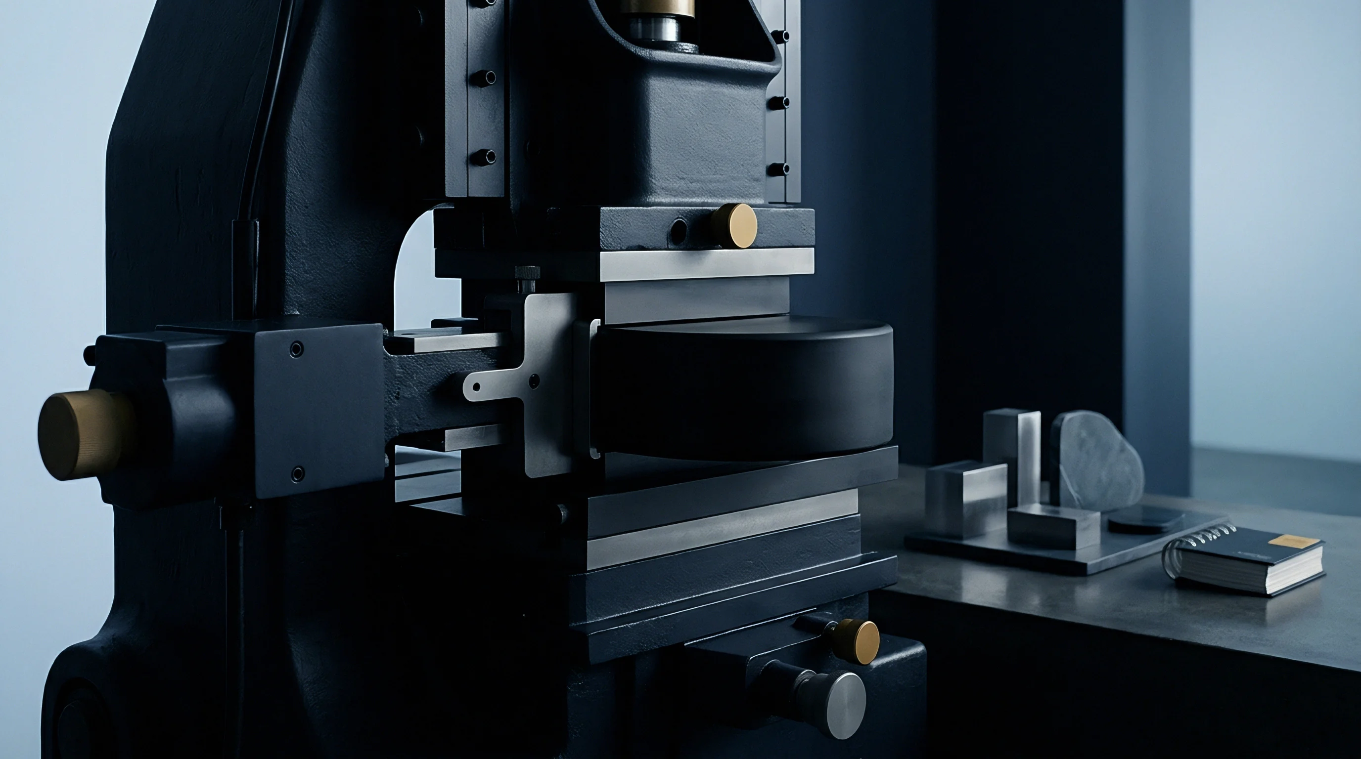
Direct Quartz Piezoelectric Transducers
Solid-state quartz elements translate instantaneous mechanical force into a proportional electrostatic output. Quartz plates cut along the crystallographic x-axis yield high charge stability across broad thermal swings. Unfilled polypropylene and polyoxymethylene flow freely over the sensor head without abrading the hardened steel diaphragm.
Highly filled compounds containing up to fifty percent chopped glass fibres cause abrasive scouring across the diaphragm face, thinning the protective membrane over several hundred thousand cycles. Toolmakers combat abrasion by specifying titanium carbo-nitride physical vapor deposition coatings on exposed sensor tips, extending transducer working life across demanding production runs.
Load Cells behind Ejector Pins
Measuring cavity conditions through moving steel pins requires exact geometric alignment. Ejector pins transfer cavity melt pressure to miniature load buttons seated securely in the ejector plate. Mechanical drag along the pin barrel corrupts the force transmission, especially when grease carbonizes under prolonged tool cycling.
Mold designers counter this variance by selecting ejector pins with clearance flats ground along their sliding lengths, minimizing contact area with the guide bushings. Ground pin faces must remain perfectly perpendicular to the load button to prevent bending moments from creating erroneous pressure peaks.

Cavity Location Selection Rules
Sensor placement dictates the analytical value of the collected signal. Placing a transducer immediately downstream of the feed orifice tracks injection dynamics, peak filling forces, and runner freeze. Positioning a sensor at the final point of fill flags short shots, venting restrictions, and sink marks caused by premature freeze-off upstream.
- Gate area placement monitors instantaneous material viscosity shifts, melt front entry velocity, and holding pressure attenuation within the immediate feed zone.
- Last-to-fill placement catches short shots caused by batch-to-batch molecular weight fluctuations or inadequate machine hydraulic volume.
- Thin-wall rib bases track localized sink and void formation where volumetric contraction outpaces packing pressure delivery.
- Weld line junctions monitor the hydraulic force driving two merging melt streams together, identifying structural weaknesses in advance.
Tool builders often complain that carving additional wiring slots and mounting holes compromises cooling line layouts and weakens core plates.


Trace
Melt compression curves reveal physical events hidden from machine controllers. When the screw drives polymer into the cold mould, the graph of cavity pressure against cycle time generates a distinct mechanical footprint. The curve separates into filling, packing, holding, and cooling intervals.
The steepness of the initial pressure rise indicates effective cavity filling rate and material viscosity at the current shear rate. Once the volumetric fill reaches ninety-eight percent, the curve hits a sharp upward inflection, signaling the end of low-resistance flow and the onset of bulk polymer compression.
Peak cavity pressure governs part density and dimensional consistency under DIN 16742 tolerance grades. Polymeric melts undergo compressibility between five and fifteen percent under pressures exceeding one thousand bar. Holding pressure forces supplementary material into the impression to compensate for the volumetric shrinkage occurring as the melt transitions from a liquid state into a semicrystalline or amorphous solid.
If the packing pressure drops before the feed channel seals, molten polymer flows backwards out of the cavity, leaving voids, poor surface finish, and loose critical tolerances.
| Curve Segment | Physical Cavity Event | Target Pressure Window (bar) | Associated Part Defect | Root Mechanical Cause |
|---|---|---|---|---|
| Filling rise | Melt front passes sensor | 50 to 300 | Hesitation lines | Excessive injection speed reduction |
| Transfer spike | Volumetric fill to pack switch | 400 to 1,200 | Flash or parting line wear | Late screw velocity transfer |
| Packing plateau | Melt compression and feed | 500 to 1,000 | Sink marks, internal voids | Insufficient holding force |
| Gate freeze inflection | Flow path freezes solid | 300 to 600 | Part weight variation | Short pack time or cold runner drop |
| Cooling decay | In-cavity thermal contraction | Atmospheric to 200 | Ejection distortion, scuffing | Over-pressurization, high mold temp |
Polymer chains relax under compression. The integral of the cavity pressure curve over time, calculated mathematically as the area beneath the pressure trace, corresponds directly to the total mass of polymer retained inside the cavity. Tracking this pressure integral across thousands of consecutive cycles provides a real-time predictor of part mass.
A downward deviation of three percent in the curve integral correlates with measurable shrinkage across critical diametrical features on polyacetal gears, taking components outside target engineering tolerances.
Uniform pressure integral curves yield uniform component mass across varying ambient factory conditions.
Environmental conditions in the moulding shop introduce process wander. Chiller temperatures drift across twelve-hour production shifts, altering steel heat extraction rates. Hygroscopic resins such as polyamide 66 exhibit viscosity drops when moisture contents climb above zero point one five percent, causing the injection pressure wave to propagate faster through the cavity.
Real-time data capture catches these micro-rheological variations on a shot-by-shot basis, identifying out-of-spec components long before quality control inspects cold parts with coordinate measuring machines.
Pressure Profile Phases across Time
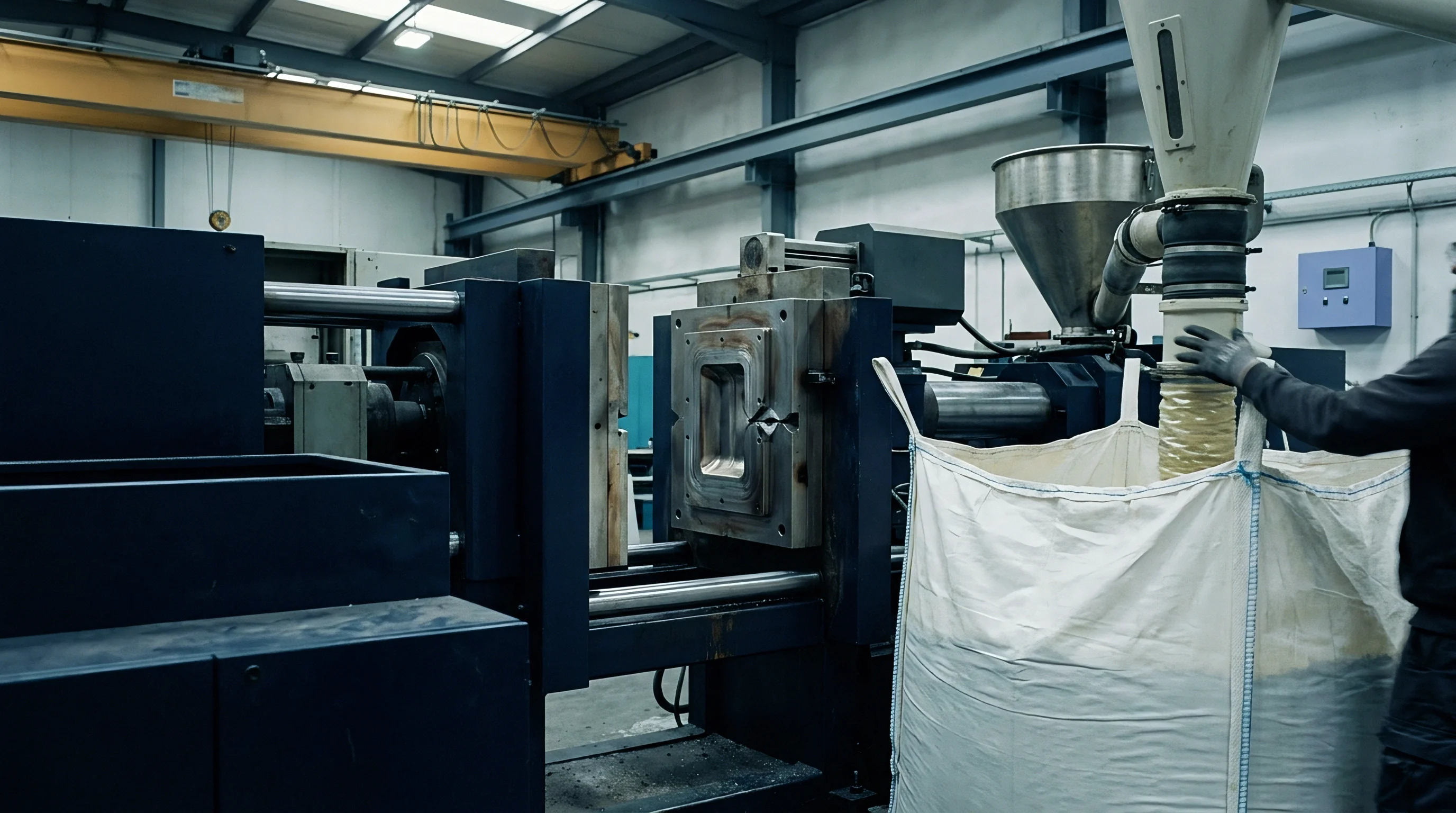
Dynamic pressure recordings expose physical transitions in the mould impression. During the filling phase, the transducer registers minimal resistive load until the cavity approaches volumetric capacity. The packing stage ramps force rapidly, compressing polymer molecules against cavity steel to duplicate tool surface textures.
The holding stage maintains hydraulic connection until the gate reaches its heat deflection temperature and solidifies. Once isolation occurs, the decay curve slopes downward, governed entirely by the thermal conduction coefficient of the steel and the cooling line layout.

Volumetric Shrinkage and Integral Pressure
Finished component dimensions depend directly on the packing pressure history sustained prior to gate seal. Semicrystalline polymers exhibit volumetric shrinkage rates between one point five and two point five percent, demanding sustained molecular packing to achieve stable crystal formation. Sinking occurs when the holding pressure profile bleeds away before the thermal core solidifies.
By computing the Riemann sum of the cavity pressure curve between transfer and gate freeze, process engineers quantify the energy transferred into the polymer matrix. Consistent integral values guarantee repeatable dimensional envelopes across production lots.

Can Piezoelectric Transducers Measure Viscosity Shifts Accurately?
Rheological behavior in the mould impression changes when material suppliers alter resin formulations or blending ratios. Melt viscosity shifts directly alter the pressure differential measured between a sensor at the gate and a sensor at the flow extremity. Calculating the pressure drop across this fixed geometric path length provides an apparent shear viscosity value during the active filling stroke.
Regrind additions increase melt flow index variations, which show up immediately as steeper or flatter pressure slopes during the filling interval. Process monitors use this instantaneous viscosity calculation to identify resin lot contamination without interrupting automatic production.
Process drift reveals that parts pack identically only when the cooling curve matches the thermal extraction of the tool.


Switchover
Machine-dependent transfer controls fail when raw material viscosity fluctuates. Traditional injection moulding presses shift from high-velocity filling to pressure-controlled packing based on screw position or hydraulic line force. If material viscosity rises due to uneven regrind blending or drying deficiencies, a fixed position switchover starves the cavity, producing short mouldings.
Conversely, lower viscosity causes the screw to drive excessive mass into the cavity before reaching the position limit, causing parting line flash and damaged tooling steel. Shifting transfer control to a cavity pressure sensor removes machine-side hydraulic variance entirely.
Scientific moulding relies on independent control stages to isolate process variables. The first stage fills ninety-five to ninety-eight percent of the cavity volume under pure velocity control, keeping injection speed constant regardless of pressure resistance. The second stage applies pure packing pressure to compensate for volumetric contraction as the resin solidifies.
The third stage isolates the cavity from the runner via thermal gate freeze. Real-time cavity pressure transfer triggers the transition to stage two the millisecond melt contacts the cavity transducer, ensuring identical volumetric filling independent of machine hydraulic lag or screw check-ring leakage.
Cold slugs jam narrow orifices. Hydraulic lines absorb mechanical energy during sudden pressure spikes, introducing phase lags between pump output and screw displacement. In high-speed packaging applications with filling times below zero point three seconds, hydraulic oil compressibility delays machine response times by twenty to fifty milliseconds.
Direct cavity pressure sensors signal the press controller through high-speed digital inputs, bypassing machine hydraulic inertia and executing the transfer command instantaneously.
DIN 16742 tolerance grades demand process capability metrics that mechanical screw-position transfer cannot hold across multi-ton resin lots.
Linear velocity changes induce non-Newtonian viscosity variations in polymer melts. Modern injection presses utilize high-response servo-electric ball screws that track command profiles within fractions of a millimeter. Even with electric drive precision, check-ring wear introduces volumetric displacement errors.
A worn non-return valve allows molten polymer to slip backward along the screw flights during the injection stroke. Cavity pressure transfer detects the resulting loss of mass flow, holding the velocity stroke until the impression reaches targeted fullness.
- Establish volumetric fill baseline by cutting off holding pressure completely and short-shooting the part to ninety-five percent of total visual volume using screw velocity control alone.
- Mount transducer at transfer trigger location, positioning the sensor face either near the gate to sense initial cavity pressurization or at the ninety-five percent fill line to catch the flow front arrival.
- Record dynamic filling pressure peaks across thirty consecutive stable cycles, calculating the standard deviation of peak pressure to verify machine hydraulic repeatability.
- Set cavity pressure threshold precisely at the value corresponding to ninety-five percent part fullness, programming the press controller to switch from velocity to pressure control upon reaching this electrical signal.
- Tune holding pressure profile to step down smoothly from the peak transfer pressure, preventing pressure spikes that generate moulded-in stress or cause tool parting plate separation.
Tooling plates separate when in-cavity forces exceed machine clamp ratings. An oversized cavity pressure spike during transfer creates flash across parting lines, forcing toolmakers to re-grind damaged shut-off surfaces. Clamping force calculation relies on multiplying total projected part and runner area by peak cavity pressure.
By bounding transfer pressures through real-time monitoring, setters safely run larger tools in smaller tonnage presses without risking mechanical deflection of the platen.

Decoupled Moulding Transfer Protocols
Decoupled processing splits part formation into distinct mechanical operations. Stage one drives the screw forward at a controlled velocity, filling the part rapidly while the material remains hot to minimize frozen skin formation. Transfer to stage two occurs before the cavity packs completely, preventing hydraulic hammer effects against cavity walls.
Stage two introduces packed mass at reduced velocity, holding part density constant until the gate freezes. Cavity pressure monitoring provides the exact switching signal needed to prevent these stages from overlapping.

Which Cavity Position Governs Transfer Reliability?
Sensor positioning governs transfer accuracy across fast-filling tools. Locating the switchover sensor near the gate measures bulk cavity pressurization as flow resistance climbs. This position provides strong signals with high signal-to-noise ratios, but it remains susceptible to gate blush and localized shear heating effects.
Locating the sensor at ninety-eight percent of volumetric fill gives direct notification that the part cavity is full. This last-to-fill position requires high transducer sensitivity, because thin-wall sections may exhibit pressure drops that leave only twenty to fifty bar of force available to trigger the machine controller.

Hydraulic Noise against Cavity Data
Comparing hydraulic readouts with cavity sensor traces exposes mechanical losses in the moulding machine. Hydraulic transducers mounted on the injection cylinder measure oil pressure, which includes the friction of the piston seals, the mechanical drag of the drive shaft, and the viscous drag of polymer along the barrel walls. Cavity sensors ignore these parasitic losses completely.
Data comparisons show that hydraulic pressure can vary by ten to fifteen percent while cavity pressure remains steady, proving that machine-side adjustments often introduce errors rather than correcting them.
Failing to decouple filling velocity from packing pressure produces severe internal stresses, resulting in warpage and field cracking across rigid parts.


Gate
Runner orifices freeze shut based on heat conduction into surrounding steel. The precise moment of gate freeze defines the termination of the packing phase. Holding pressure applied after the gate solidifies consumes electrical energy without adding polymer mass to the part cavity.
Releasing holding pressure before gate freeze allows pressurized melt to discharge back into the cold runner, dropping part weight and causing severe sink marks over heavy wall sections. Cavity pressure curves reveal the exact second gate freeze occurs through an observable inflection in the cooling slope.
Wall thickness dictates thermal dissipation. Semicrystalline polymers like polybutylene terephthalate exhibit rapid solidification due to their high melting points and crystalline latent heat release. Amorphous polymers like polycarbonate transition over a broad glass transition window, prolonging gate freeze times.
Process technicians determine gate freeze by conducting manual part-weighing studies across varying hold times. Cavity pressure monitoring automates this evaluation: when changes in machine holding time no longer alter the pressure decay curve inside the cavity, the gate has frozen shut.
Multi-cavity tooling introduces fill imbalance challenges. Natural balancing requires runner systems to feature identical flow lengths, runner diameters, and gate dimensions across all impressions. Even in geometrically balanced tools, shear-induced heating creates thermal imbalances between inner and outer cavities.
Resin flowing through the center of the melt stream remains hotter than resin shearing along runner walls, directing lower-viscosity material into specific cavities. Individual transducers mounted in each cavity expose these distribution discrepancies instantly.
Holding pressure applied after gate seal wastes energy and accelerates mechanical check-ring wear without adding material to the cavity.
Mould cooling channel placement dictates gate seal consistency across large tools. Water circuits running closer to one impression drop its steel temperature, freezing its gate seconds ahead of neighbouring cavities. The cavity with the open gate continues to accept packing melt, increasing its part weight and changing its shrink rate.
Transducers installed across multiple cavities display divergent pressure profiles, identifying which cooling circuits require rebalancing or scale removal.

Solidification Detection through Decay Rates
Monitoring cooling decay curves eliminates the need for manual gate freeze experiments. During active packing, the cavity pressure curve mirrors machine holding pressure fluctuations. When the feed channel freezes, the cavity transducer decouples from the machine nozzle, and the pressure curve transitions into an uninterrupted logarithmic decay driven solely by volumetric thermal shrinkage.
Detecting this transition point enables setters to optimize hold times to within one-tenth of a second, shaving cycle time from mass production runs without compromising dimensional stability.

Cavity Imbalance in Multi Impression Tools
Balanced filling across multi-cavity moulds ensures uniform part dimensions across all tool impressions. Imbalanced flow fronts cause early-filling cavities to pack prematurely under full injection pressure while slower cavities are still filling, resulting in flash on early parts and short shots on late parts. Installing sensors across all cavities allows engineers to pinpoint runner flow restrictions.
Toolmakers adjust gate lands and runner diameters by tenths of a millimetre, referencing real-time cavity data to equalize pressure delivery across every cavity.
Whether cooling channel fouling or shear-induced viscosity variance contributes more to cavity-to-cavity weight divergence remains open for debate across mould shops.


Sort
Automated part containment prevents defective mouldings from entering the assembly stream. Cavity pressure systems interface directly with press control units and parts-handling robots. When the peak cavity pressure, pressure integral, or cooling decay rate breaches programmed tolerance envelopes, the monitor fires a reject signal.
The machine controller triggers an automated divert chute or instructs the end-of-arm tooling robot to drop the suspect shot into a scrap bin rather than onto the downstream conveyor.
Defective parts drop down separate chutes. Sourcing contracts for automotive connectors, medical syringes, and optical lenses demand zero-defect delivery standards. Traditional quality control relies on statistical batch sampling, measuring five parts per thousand on visual inspection benches.
This manual method allows defective parts generated during transient thermal shifts or midnight machine restarts to pass through unnoticed. In-cavity pressure verification evaluates every single shot against calibrated process boundaries, creating an uninterrupted quality ledger.
| Production Metric | Unmonitored Tooling | Single-Sensor Setup | Multi-Cavity Complete System |
|---|---|---|---|
| Sensor and controller tooling capital | $0 | $6,500 | $24,000 |
| Scrap rate across annual volume | 3.8% | 1.2% | 0.3% |
| Cycle time per shot (seconds) | 22.5 | 20.8 | 19.4 |
| Annual scrap sorting labour cost | $18,000 | $4,000 | $0 |
| Net payback horizon (months) | Baseline | 5.2 | 8.7 |
Capital expenses for sensor integration balance against scrap reduction and cycle time compression. Equipping a thirty-two cavity tool with individual piezoelectric transducers, junction hubs, and high-speed data acquisition racks increases tooling invoices by twenty to thirty thousand dollars. However, optimizing packing and cooling times through real-time gate seal identification frequently shaves one to three seconds off cycle times.
In high-volume operations running millions of shots annually, a two-second cycle reduction recovers the upfront sensor investment within months on machine-hour savings alone.
Machine displays hide mold realities. Barrel temperatures drift overnight. Tool steel alterations drain project budgets.
By using cavity sensors to reject bad shots before parts reach secondary packaging, moulders avoid customer chargebacks and warranty penalties. The desk operates under realistic capital figures: while instrumentation quotes range from six thousand to thirty thousand dollars depending on cavity count, the true expenditure rests on internal team training, preventative maintenance of sensor channels, and regular calibration routines.

Automated Rejection at the Press
Robotic part separators utilize cavity pressure digital outputs to segregate suspect production. The data acquisition monitor checks multiple parameters per cycle, including filling time, peak cavity pressure, pressure integral, and gate seal time. If any single parameter violates upper or lower control limits, a discrete twenty-four volt output changes state before the mold opens.
Pneumatic divert gates switch direction within two hundred milliseconds, funneling rejected parts into containment bins for material regrinding or destruction.
Transducer Capital against Part Cost
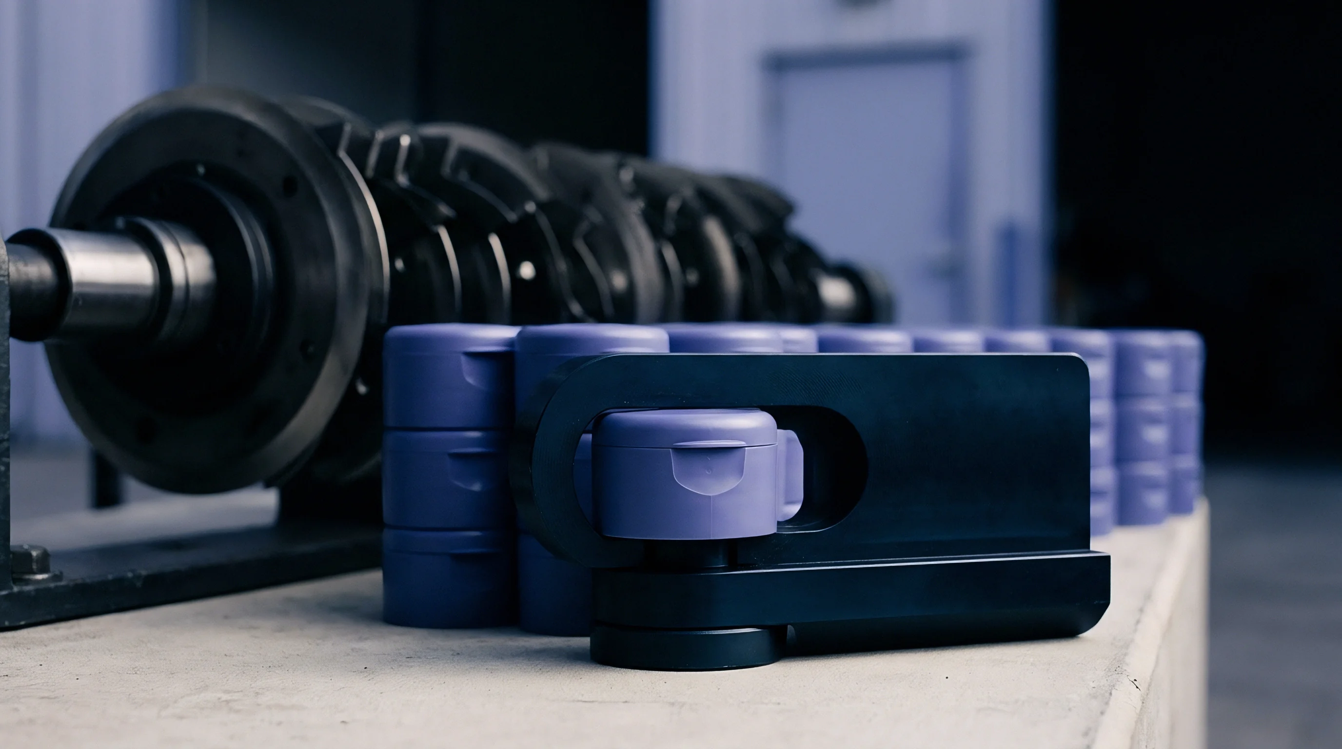
Procurement teams evaluate sensor integration costs against piece price savings. High-cavitation tools produce large volumes of parts where material costs represent sixty to seventy percent of the overall part economics. Preventing the production of non-conforming parts minimizes resin consumption, regrind thermal degradation, and runner waste.
Eliminating offline quality inspection labour lowers operating overheads, allowing moulders to offer lower piece part prices while maintaining healthy gross margins.
Purchase contracts specifying zero non-conforming parts per million enforce strict containment clauses that assign all quarantine and sorting expenses to the supplier whenever unmonitored production escapes quality gates.