Preventing Valve Pin Misalignment Caused by Hot Runner Drift
Compensate thermal drift by machining cold offset nozzle drops, installing floating bushings, and decoupling valve pin heads from rigid press actuators.
Kinematics
Thermal expansion across a hot runner manifold pushes nozzle drops out of alignment with cold gate orifices in the cavity plate. In an eight-drop system running polypropylene at 230 degrees Celsius inside a mould base held at 30 degrees Celsius, a 400-millimetre manifold expansion pitch produces up to 1.04 millimetres of outward radial shift from the thermal center. When valve pins remain tied to actuators on a rigid backing plate or an uncompensated top clamp plate, that lateral movement forces the pin shafts into angular deflection along the drop axis.
The resulting bending moment drives the hardened tip directly against the perimeter of the gate orifice. Rather than seating dead center in the gate land with a uniform circumferential clearance of 0.005 to 0.008 millimetres, the pin rubs one flank on every stroke, driven by hydraulic or pneumatic actuation pressures exceeding 4.5 megapascals. The first sign on the floor is faint vestige flash, followed quickly by galling, gouged rings around the pin stem, and eventual fracture of the brittle carbide or tool-steel pin.
A thirty-millimeter lateral shift across an uncompensated manifold drops tool steel directly into the path of fatigue fracture within ten thousand dry cycles.
Calculating the true displacement vector requires accounting for the temperature differential between the manifold alloy and the surrounding backing plates. DIN 1.2312 and DIN 1.2344 tool steels exhibit a linear thermal expansion coefficient of approximately 12.8 to 13.2 micro-metres per metre kelvin within the 20 to 250 degrees Celsius processing range. The equation governing this behavior defines cold-to-hot location shifts:
Delta L = L_0 times alpha times Delta T
A nozzle drop spaced 200 millimetres from the manifold locating ring experiences a nominal outward travel of:
200 mm times (13.0 times 10^-6 / K) times (230 C – 30 C) = 0.520 mm
If the actuator cylinder is bolted directly to a top clamp plate running at coolant temperature, the cylinder axis stays parked at 200.000 millimetres while the nozzle bore shifts to 200.520 millimetres. As the pin guide bushing in the hot manifold drags the pin stem outward, the actuator seal holds the top pinned. That creates severe mechanical bind inside the melt seal pack.
Injection pressures entering the manifold bore worsen this misalignment with asymmetric hydraulic side loads against the stem, warping the pin along its unguided length inside the melt channel.
Galling along the gate land accelerates permanent cavity damage, scrapping thousands of parts and bringing multi-cavity runs to a halt.
Dowel
What Thermal Offset Compensates Radial Expansion?
Centering rings and locating dowels define the thermal anchor from which manifold growth radiates. A precision-ground round locator at the physical center balances expansion across all four quadrants, cutting maximum individual nozzle displacement in half compared to an end-fixed arrangement. Toolmakers compensate for this by boring nozzle seats in the hot manifold with a deliberate cold offset, machining each drop bore closer to the center by the calculated expansion distance.
Once the tool reaches steady-state processing temperature, the manifold grows outward until the drop bores align coaxially with the water-cooled gate orifices. Cold assembly leaves the valve pin visibly tilted or eccentric relative to the nozzle tip. Tool setters must avoid cycling the valve pin actuation system while the manifold remains cold, as stroking valve pins at ambient temperature drives the hardened tips directly into cold gate walls, gouging the orifice before production begins.
| Distance from Center (mm) | Manifold Steel Grade | Operating Temp (C) | Radial Expansion (mm) | Cold Machining Offset (mm) |
|---|---|---|---|---|
| 100.0 | DIN 1.2344 | 220 | 0.247 | -0.247 |
| 150.0 | DIN 1.2344 | 220 | 0.371 | -0.371 |
| 200.0 | DIN 1.2344 | 240 | 0.546 | -0.546 |
| 250.0 | DIN 1.2312 | 260 | 0.748 | -0.748 |
| 300.0 | DIN 1.2312 | 280 | 0.975 | -0.975 |
| 400.0 | DIN 1.2738 | 290 | 1.383 | -1.383 |
Thermal stability requires strict mechanical constraint along the non-expanding center axis. Tool designers turn to precision-ground flat keys or sliding cross guides rather than relying entirely on a single central round pin. Sliding dowels running in machined keyways permit thermal growth cleanly along nozzle drop centerlines while preventing the entire manifold block from twisting.
If loose guide dowels let the manifold twist even 0.05 degrees off-axis, outer nozzle gates suffer compound angular misalignments. Uneven manifold heater bands cause a similar imbalance: when one side heats faster than the other, asymmetric thermal profiles skew the expansion vectors, causing nozzles to veer off their calculated paths and forcing valve pins into gate lands skewed across two separate planes.
Under DIN 16742 Group 130 tolerances, unguided thermal skewness consumes the entire permissible gate land clearance before mould clamping occurs.
Alignment features hold true position only when the central anchor absorbs the shear loading created by thermal growth.
Bush
Can Floating Guiding Elements Prevent Seizure?
Piston-driven valve pins traverse two distinct thermal zones: the heated melt environment inside the hot runner and the chilled steel plates enclosing the cavity. The melt seal bushing acts as the dynamic interface between them, guiding the pin stem while containing polymer melt. To prevent resin from leaking into the cylinder plates, diametral clearances between pin and bush stay tight, typically running 0.008 to 0.012 millimetres for unfilled technical resins such as polyoxymethylene or polyamide 66.
When the manifold drifts, a fixed guide bushing forces the pin to flex across this narrow gap. At temperatures above 200 degrees Celsius without lubrication, unyielding steel contact causes galling within seconds. Advanced hot runner systems implement floating guide bushings seated in precision-machined pockets with floating retaining plates.
These assemblies allow the bushing to follow minor manifold expansion variations while maintaining concentric alignment around the pin axis.
- Hardened Bushing Steels incorporate powdered metal grades such as CPM 9V or carbide inserts hardened above 62 HRC to resist continuous sliding friction under melt pressures exceeding 150 megapascals.
- Scraper Ring Geometries clear degraded polymer char from the pin surface during backward retraction strokes, preventing residue from packing inside the guidance bore.
- Direct Lubrication Channels feed high-temperature perfluoropolyether lubricants into dynamic sealing rings to drop friction coefficients below 0.08 during continuous production cycles.
- Thermal Break Insulators separate the hot guidance sleeve from chilled backing plates, keeping internal guidance surfaces below the thermal degradation threshold of sensitive resins.
Piston binding often traces back to debris packing into tight guide clearances. Extended residence times degrade resins like polybutylene terephthalate into acidic breakdown products that pit guide bush flanks. Those eroded surfaces grip the pin shaft and create lateral drag that pulls the tip away from gate centerlines.
Pin wear accelerates dramatically when glass-filled resins enter the guide interface, where broken fibers act as dynamic lapping compounds.
Early pin wear often passes for ordinary operational friction when the root problem is poor thermal compensation geometry in the manifold housing.
Actuation
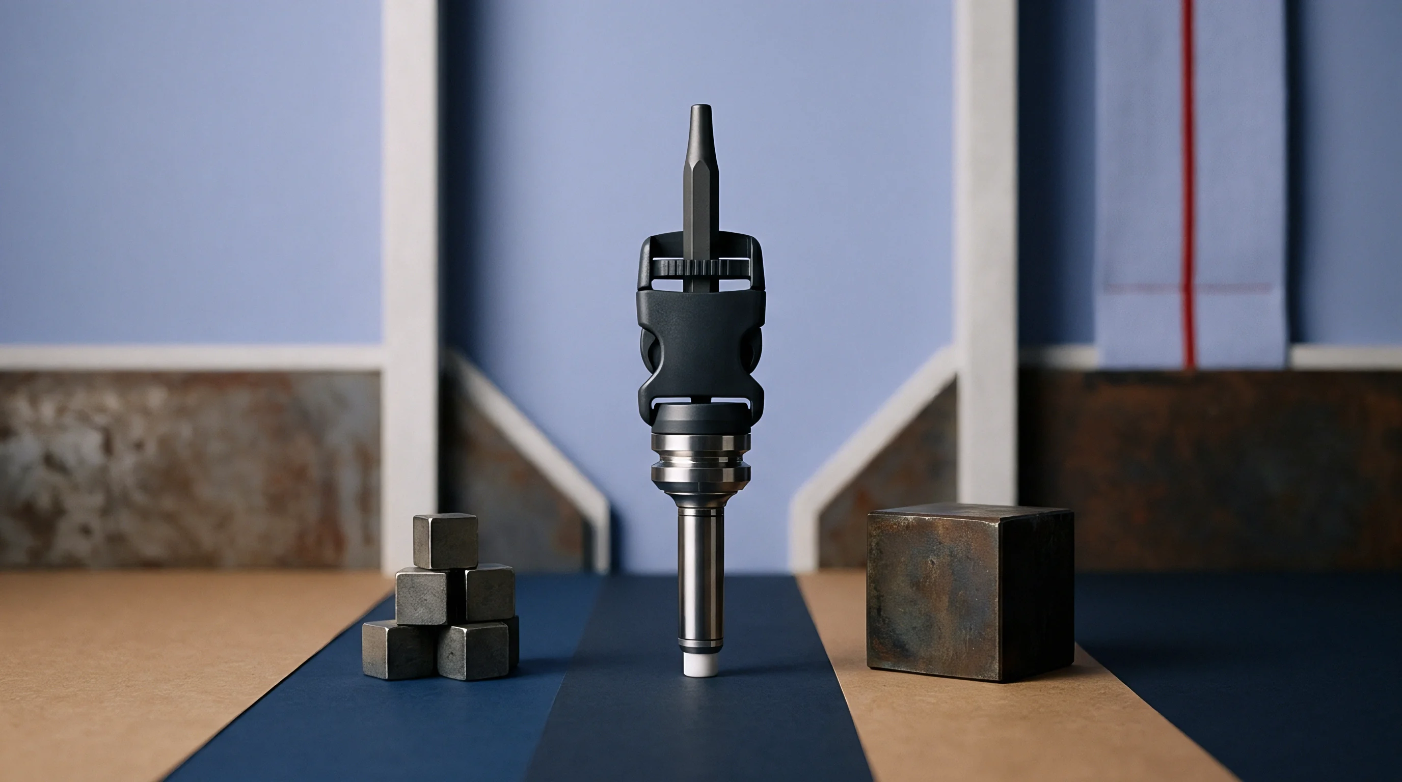
Actuator location dictates the mechanical vulnerability of the valve pin assembly. When individual pneumatic or hydraulic cylinders mount directly onto cold backing plates, the cylinder piston stays pinned to a static position while the lower tip moves with the heated nozzle. The resulting angular canting bends the pin throughout its length.
Progressive tool shops decouple the pin head from the piston rod using floating T-couplers or spherical radius linkages.
A spherical coupling permits the pin head to translate laterally up to 1.5 millimetres without imparting bending moments to the actuator piston. The piston continues its linear stroke perpendicular to the backing plate, while the pin tilts slightly or floats laterally inside an articulated shoe. Plate-actuated valve gate systems present a different mechanical scenario: in sync-plate systems, all valve pins lock into a single reciprocating plate driven by hydraulic cylinders or servo-electric toggle drives.
A mechanical decoupler between pin and piston removes bending stress across forty thousand production hours.
If the manifold drifts relative to the sync plate, every single valve pin deflects simultaneously in identical outward directions. Servo-driven sync plates provide programmable velocity profiles that reduce impact shock when pins seat into gates. Slowing pin velocity from 300 millimetres per second down to 25 millimetres per second over the final 0.8 millimetres of stroke allows the tapered pin head to center itself gently into the conical lead-in of the gate insert.
- Mount precision dial indicators against the cold manifold block to measure initial baseline clearances across all locating dowels.
- Heat the runner block gradually in 50-degree Celsius increments, holding each stage for twenty minutes to eliminate localized thermal gradients.
- Measure outward growth at each nozzle drop using high-accuracy optical coordinate equipment to verify mathematical expansion calculations against actual steel movement.
- Stroke the valve gate mechanism manually using low-pressure shop air at 0.2 megapascals to verify smooth travel without mechanical binding or acoustic friction signs.
- Inspect pin tips through the open gate inserts with an optical borescope to confirm perfect concentricity before bolting cavity plates into position.
Uneven hydraulic fluid temperature across cylinder banks can introduce fractional timing variations that distort the symmetric seating of synchronized pins across large-tonnage tools.

Allowance
Tooling quotes for large multi-drop valve gate tools often gloss over the financial exposure created by unstated alignment tolerances. A sixteen-drop hot runner system running on an uncompensated manifold demands continuous maintenance that can double the initial tooling purchase cost over its operating life. Tool procurement contracts must quantify thermal drift parameters directly in machining specifications, with clear contractual clauses defining acceptable pin-to-gate concentricity under steady-state thermal conditions.
Acceptance protocols require full dimensional verification at operational temperatures. Toolmakers verify that pin eccentricity remains within 0.003 millimetres of gate orifice centers across three consecutive production shifts running at commercial cycle rates. Missing this threshold triggers rework penalties or replacement of defective sliding manifold carriers at the toolmaker’s expense.
Tool ownership transfers only after process capability studies confirm Cpk values above 1.67 on critical gate vestige dimensions.
| Failure Category | Root Mechanical Cause | Immediate Part Defect | Toolroom Repair Cost (USD) | Down Time (Hours) |
|---|---|---|---|---|
| Gate Flank Gouging | Uncompensated Radial Drift | Elongated Vestige, Flashing | 4500 to 8000 | 36 |
| Pin Stem Seizure | Bushing Clearance Collapse | Incomplete Cavity Fill | 1200 to 2500 | 12 |
| Piston Seal Extrusion | Angular Binding Moment | Hydraulic Fluid Leakage | 800 to 1800 | 8 |
| Tip Fatigue Shear | Cyclic Off-Center Strike | Blocked Gate, Cavity Shutoff | 6000 to 14000 | 48 |
| Manifold Thread Yield | Thermal Key Binding Strain | Polymer Melt Blowout | 15000 to 32000 | 120 |
Spare parts provisioning represents another direct capital outlay tied to pin drift. Tools engineered without floating decouplers consume up to four times more replacement pins and gate inserts than properly compensated systems. Procurement teams budgeting for 100,000-shot cycles must incorporate the replacement cost of custom-machined carbide components into baseline piece-price models.
Investing five to eight percent more upfront for floating guide bushings and sliding dowel assemblies yields immediate payback by preventing catastrophic mould breakdowns during ramp-up.
Supply agreements standardizing DIN ISO 16916 runner components specify that tool sign-off remains withheld until cold-start and hot-running alignment certifications show zero plastic deformation across all mechanical guidance pins.