Instrument Transfer Function Verification for Optical Profilometry in Narrow Cavities
Verifying instrument transfer function in narrow cavities requires chirp artifact calibration to correct spatial frequency attenuation from optical vignetting.

Bore
Optical Obscuration in Deep Tooling Slots
Narrow tool steel cavities in micro-fluidic plates, electrical connector housings, and rib channels present steep geometric boundaries that obstruct optical measurement paths. High-aspect-ratio trenches restrict the entrance and exit angles of reflected light. Coherence scanning interferometry and confocal profilometry rely on high numerical aperture objective lenses to collect scattered light from textured surfaces.
Once a cavity depth exceeds four times its width, vertical steel walls physically cut off the peripheral illumination cone.
Light rays striking high-frequency micro-geometry at high angles scatter into the cavity walls rather than returning to the objective lens. This numerical aperture truncation shifts the effective optical bandwidth of the profiler toward lower spatial frequencies. The instrument loses the ability to resolve fine surface roughness features, producing artificially smooth profile traces that fail to record spark erosion pits or micro-chatter marks.
| Aspect Ratio | Nominal Objective NA | Effective Cavity NA | Maximum Observable Slope | Signal Attenuation |
|---|---|---|---|---|
| 1:1 | 0.55 | 0.53 | 31.2 deg | 0.4 dB |
| 4:1 | 0.55 | 0.28 | 15.8 deg | 4.2 dB |
| 8:1 | 0.55 | 0.12 | 6.7 deg | 14.1 dB |
| 12:1 | 0.55 | 0.07 | 3.8 deg | 22.8 dB |
Numerical Aperture Reduction and Shadowing
Inside a constrained cavity slot, effective numerical aperture scales directly with clear aperture geometry. A 20x objective lens with a nominal numerical aperture of 0.40 operating in open air collects light across a half-cone angle of 23.5 degrees. Lowering that objective into a 0.5 millimeter wide slot at a focal depth of 3.0 millimeters constrains the physical light path: sidewalls restrict the half-cone angle to less than 4.8 degrees, reducing effective numerical aperture to approximately 0.08.
An aspect ratio exceeding 6:1 reduces effective numerical aperture below 0.12, truncating spatial frequency detection above twenty cycles per millimeter.
Shadowing along trench edges creates secondary reflection phenomena. Light striking vertical cavity walls bounces back onto the floor surface, introducing secondary phase delays into interferometric signals. The instrument detector records phantom height steps or false low-frequency waves across the bottom floor.
Quality personnel reading raw profile data risk misinterpreting optical reflection noise as geometric wall draft or floor curvature.
Failing to compensate for optical obscuration produces false surface roughness readings. That leads either to unearned tool rejects or to uncorrected mould friction, causing premature ejection pin failure during high-volume production shifts.

Fidelity

Spatial Frequency Response and Transfer Functions
Metrology systems exhibit a specific frequency response curve known as the Instrument Transfer Function, which defines the ratio of measured surface amplitude to actual physical amplitude across a spectrum of spatial frequencies. On flat, open calibration samples, an optical profiler maintains a transfer ratio near unity across lower and mid-range spatial frequencies before dropping off at the optical resolution limit.
Vignetting inside narrow channels distorts this transfer behavior. Spatial frequencies that pass unattenuated on open steel surfaces undergo heavy amplitude suppression when measured at the bottom of a deep slot. The loss of high-angle light components reduces contrast, pulling measured profile amplitude far below the physical peak-to-valley height of the surface texture.
Consider a hardened H13 tool steel core pin trench evaluated for micro-injection moulding. The target floor texture produced by sink-errosion electrical discharge machining carries a physical pitch of 10 micrometers, corresponding to a spatial frequency of 100 cycles per millimeter. On an open test block, a coherence scanning profiler records 88 percent of the true 0.40 micrometer peak-to-valley height.
Inside a slot with a 6:1 aspect ratio, signal attenuation reduces the recorded peak-to-valley amplitude to 0.12 micrometers ~ yielding a profile that appears 70 percent smoother than the physical surface.
Spatial bandwidth attenuation in deep cavity profilometry masks micro-roughness peaks while leaving macro-form dimensions unchanged.

Power Spectral Density Attenuation Mechanics
Analyzing raw surface profiles using Power Spectral Density distributions exposes the specific frequencies where optical attenuation degrades profile accuracy. High-frequency electrical discharge machining pits contribute directly to polymer melt adhesion and demoulding force. When spatial frequencies above 50 cycles per millimeter drop below the noise floor of the optical detector, the profilometer underestimates the surface area of the cavity floor.
Multiple optical phenomena combine to accelerate spatial bandwidth loss in deep slots.
- Aperture vignetting clips outer illumination rays, converting high-frequency spatial detail into attenuated low-amplitude sine waves.
- Sidewall glare introduces uncorrelated phase shifts that raise the measurement noise floor across mid-range spatial frequencies.
- Multiple reflections fold light paths inside narrow geometries, creating false spectral peaks in recorded spatial power distributions.
- Focus variation degradation suffers from reduced local contrast, blurring localized scratch edges into smooth surface undulations.
Optical profile measurements taken in cavity slots deeper than their entrance width require physical verification against calibration standards mounted at identical focal depths.
Gauge

Does ISO 25178 701 Define Spatial Cutoffs in Deep Cavities?
International standard ISO 25178-701 details physical material measures used to calibrate optical profilometers. Step-height standards, sinusoidal gratings, and material measures containing deterministic chirp patterns calibrate system gains and spatial limits. Standard calibration routines execute on open flat stages where objective lenses operate without beam clipping.
Consequently, calibration data gathered on an open microscope stage yields transfer function curves with little relevance to measurements taken deep inside narrow slots.
Verifying transfer performance inside narrow channels demands specialized reference artifacts. Precision electroforming or ion-beam milling can write chirp structures directly onto the floor of narrow steel channels, creating recessed calibration targets with spatial frequencies running from 5 cycles per millimeter up to 500 cycles per millimeter at certified step heights.
| Slot Depth | Target Frequency | Nominal ITF Ratio | In-Slot ITF Ratio | Attenuation Correction |
|---|---|---|---|---|
| 0.5 mm | 50 cycles/mm | 0.96 | 0.91 | 1.05x |
| 2.0 mm | 50 cycles/mm | 0.96 | 0.74 | 1.30x |
| 4.0 mm | 50 cycles/mm | 0.96 | 0.42 | 2.28x |
| 8.0 mm | 50 cycles/mm | 0.96 | 0.11 | 8.72x |

Physical Chirp Standards and Step-Height Fixturing
Evaluating transfer functions across multiple cavity depths requires modular calibration target holders. Adjustable fixtures position recessed chirp standards at controlled distances from the optical lens, mimicking production tool geometry. Measuring height responses across the frequency range establishes an empirical transfer correction matrix for each specific cavity depth.
Compliance with ISO 25178-603 mandates instrument transfer function reporting across the full spatial bandwidth utilized for surface texture parameter calculation.
Engineers selecting reference standards for deep cavity metrology apply specific physical parameters to guarantee calibration validity.
- Chirp wavelength ranges span spatial pitches from two hundred micrometers down to one micrometer to capture full bandwidth drop-off.
- Substrate reflectivity matching replicates tool steel optical reflection properties to prevent artificial signal contrast shifts.
- Channel wall aspect matching mirrors production mould slot width and depth to enforce identical numerical aperture clipping.
- Depth-adjustable mountings position reference surfaces precisely at operational focal planes within high-aspect fixtures.
Tool procurement specifications enforcing ISO 25178-603 calibration clauses require depth-equivalent ITF verification records before sign-off documentation authorizes final tooling payments.

Discrepancy
Tactile Profile Comparison and Replicating Polymers
Measurements performed directly inside narrow cavities using non-contact profilers routinely diverge from tactile stylus records. A diamond stylus with a 2-micrometer tip radius drops directly into deep slots, keeping physical contact with the cavity floor regardless of sidewall height. Physical contact profiling avoids optical vignetting entirely, providing a mechanical baseline for profile amplitude verification.
Direct stylus probing in narrow slots carries operational risks: rigid stylus arms cannot access slots narrower than 0.3 millimeters without damaging delicate cavity walls. High-resolution silicone metrology polymers offer a non-destructive alternative. Technicians pour liquid polyvinylsiloxane into narrow cavity slots, allowing the compound to cure into a flexible negative replica.
The cured rubber replica is withdrawn from the slot and measured on an open optical profiler or stylus instrument.
- Dispense high-resolution polyvinylsiloxane resin into the dry, degreased tool steel cavity slot.
- Apply twenty kilopascals of pressure to force fluid polymer into micro-scale surface crevices.
- Allow full chemical cross-linking for six minutes at ambient toolroom temperatures.
- Extract the elastomeric replica using non-marring brass tweezers to prevent edge tearing.
- Mount the replica on an open optical profiler stage with the textured floor facing upward.
- Measure surface profile parameters across open optical geometry free from sidewall clipping.
- Invert measured profile heights mathematically to compensate for negative replica geometry.
- Compare replica spatial profiles against direct in-cavity optical scans to quantify optical filtering loss.
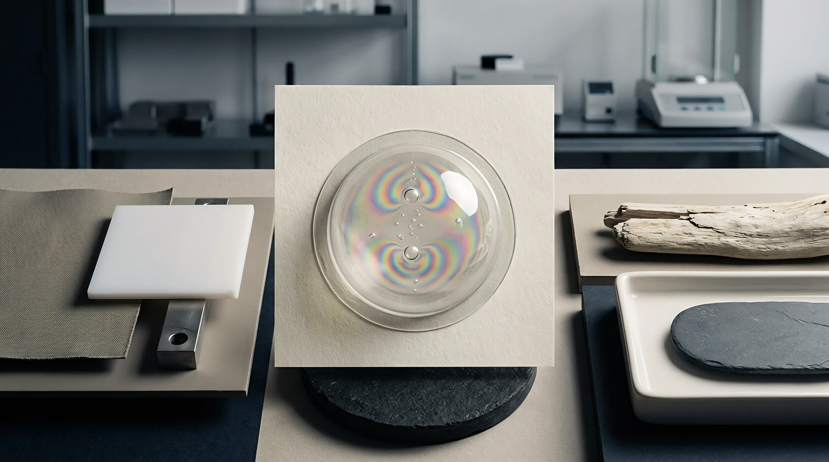
Replication Fidelity in Micro-Tooling Verification
Polyvinylsiloxane polymers reproduce surface features down to sub-micron dimensions. Comparing replica measurements against direct in-cavity optical profiles isolates the exact transfer function losses caused by geometry constraints. Difference curves show where direct optical scanning underreports surface roughness due to numerical aperture attenuation.
Slope limitations inherent to optical profilometry create additional errors on steep spark-eroded textures. The maximum detectable surface slope angle scales with numerical aperture according to the arc sine of the effective numerical aperture. When effective numerical aperture drops to 0.15 inside a deep trench, the maximum measurable slope limits out at 8.6 degrees.
Surface features with local slopes of 25 degrees reflect light outside the collection cone, leaving unmeasured points or artificial profile flattening.
Attributing surface texture discrepancies to optical profilers capturing fine topography that stylus needles destroy leaves out the optical vignetting that flattened the recorded peaks.

Invoice

Commercial Risk Allocation in Precision Tooling Acceptance
Tooling sign-off disputes emerge when optical profilometry reports compliant surface finishes inside narrow cavity slots, but injection moulded parts exhibit severe wall dragging, haze, or stress whitening upon ejection. Re-machining, polishing, or replacing damaged cavity inserts imposes heavy financial charges. Identifying metrology errors before tool steel ships prevents costly factory downtime and rework friction between toolmakers and moulding operators.
Consider a 16-cavity electrical connector mould costing $120,000. Each cavity contains eight narrow pin slots with specified surface roughness limits of Ra 0.10 micrometers. Uncalibrated in-cavity optical profilometry records an average Ra of 0.07 micrometers, prompting tool sign-off.
During initial sampling on a 100-tonne press, high demoulding friction causes pin distortion and ejector mark deformation. Retesting cavity floors via silicone replication reveals actual physical roughness values of Ra 0.22 micrometers. Polishing 128 narrow pin slots by hand costs $18,400 in specialized toolroom labor and delays production release by three weeks.
| Failure Mechanism | Detection Stage | Direct Rework Cost | Production Downtime | Commercial Liability |
|---|---|---|---|---|
| Unrecorded EDM Pit Roughness | First Article Inspection | $18,400 | 21 Days | Toolmaker Warranty |
| False Slope Angle / Draft Loss | Pilot Production Run | $34,000 | 35 Days | Shared Allocation |
| Sidewall Glare Optical Artifacts | Tool Sign-Off Audit | $2,800 | 3 Days | Metrology Lab Cost |
| Uncorrected Transfer Attenuation | Full Volume Shift | $86,000 | 60 Days | Moulder Operating Loss |
Contractual Verification Protocols for Micro-Cavity Roughness
Purchasing contracts for high-precision injection tooling must codify metrology verification conditions. Simple quality requirements specifying surface roughness parameters without defining optical measurement conditions invite commercial disputes. Procurement documentation should state the required transfer function verification methodology for any cavity slot with an aspect ratio exceeding 3:1.
Tooling acceptance based on raw optical profiles frequently transfers polishing labor onto injection moulding production shifts.
Inserting strict metrology qualification language protects tooling capital. Contracts specifying depth-equivalent transfer function validation ensure that reported surface parameters reflect real steel conditions. Toolmakers must supply verified instrument transfer calibration records alongside raw surface profile datasets prior to final invoice settlement.
Whether dynamic numerical aperture synthesis through multi-angle illumination can eliminate physical replication steps in narrow cavity inspection remains an open question in the metrology community.