Dynamic Micro-Asperity Viscoelastic Deformation Modeling at Polymer Steel Boundaries under High Packing Hydrostatic Stress
High packing stress forces polymer skins into steel micro-grooves, increasing heat transfer while elevating ejection drag through viscoelastic keying.

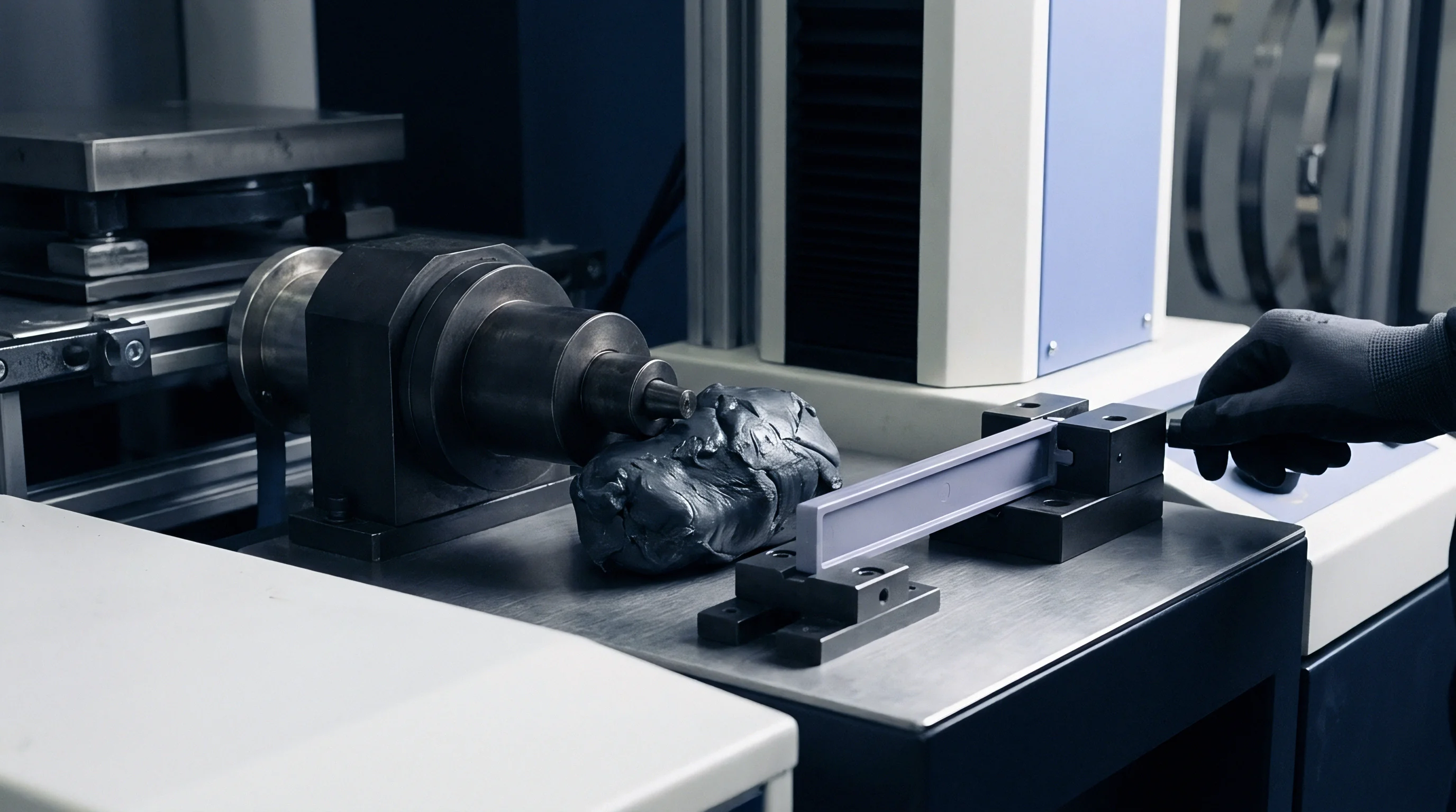
Ridge
Cavity steel topography under high hydrostatic packing pressure acts as a dynamic mold boundary rather than a rigid static plane. During the injection moulding packing phase, melt pressures between 800 bar and 1600 bar force the molten polymer matrix into microscopic tool surface valleys. Standard surface roughness metrics such as average roughness Ra fail to capture this interaction because two tool surfaces with identical Ra values can exhibit radically different micro-asperity peak distribution, skewness Rsk, and kurtosis Rku.
Tool surfaces machined via electrical discharge machining display non-directional cratered profiles with negative skewness. Ground or polished cavity inserts display directional grooves with sharp positive peaks. High hydrostatic pressure forces the polymer interface to conform around these metallic peaks, transforming theoretical point contacts into flattened plastic contact patches.
Contact area fraction increases non-linearly with packing pressure, rising from under ten percent at cavity fill to over eighty percent at peak hydrostatic packing.
Polished tool steel surfaces with positive profile skewness produce higher mechanical keying than ground tool steel surfaces with identical arithmetic average roughness values.
Micro-asperity deformation begins when the hydrostatic pressure exceeds the initial compressive yield stress of the solidifying outer polymer skin. The metallic peaks of tool steel 1.2343 hardened to 52 HRC undergo purely elastic deflection under maximum packing pressures. The polymer skin undergoes localized viscoelastic flow, creeping into micro-grooves and encapsulating sharp steel asperities.

Surface Topography Metrics under Packing Hydrostatic Stress
Characterizing the boundary micro-geometry requires parameters that capture peak sharpness and surface void volume. Arithmetic mean deviation Ra provides an incomplete picture of boundary geometry. Root mean square roughness Rq combined with core roughness depth Rk isolates the load-bearing portion of the tool surface from deep oil-retaining valleys.
Zero skewness represents a Gaussian height distribution. Positive skewness indicates sharp isolated peaks rising above a flat plane, which concentrate boundary shear stresses during melt flow. Negative skewness describes a surface composed of flat plateaus pitted with fine pores, offering lower resistance to initial cavity filling while maintaining adequate thermal contact conductance under pack pressure.
| Finishing Method | Arithmetic Roughness Ra (µm) | Profile Skewness Rsk | Contact Area Fraction (%) | Thermal Contact Conductance (W/m²K) |
|---|---|---|---|---|
| SPI A1 Mirror Polish | 0.012 | +0.15 | 92.4 | 2850 |
| SPI B2 Fine Paper | 0.060 | +0.42 | 74.1 | 2100 |
| EDM VDI 18 Fine Spark | 0.800 | -0.35 | 58.6 | 1450 |
| EDM VDI 24 Medium Spark | 1.600 | -0.52 | 41.2 | 980 |
Mechanical interaction at the micro-scale dictates both heat transfer efficiency and part release forces. Sharp steel peaks penetrate the solidifying polymer melt layer, creating an array of microscopic mechanical keys. Increased contact area fraction enhances heat flux across the tool interface, shortening cycle times at the expense of higher ejection forces.
Tool designers control boundary keying through targeted surface treatments. Diamond-like carbon coatings and physical vapor deposition coatings lower the surface energy of the tool steel. Lower surface energy prevents the polymer from wetting the metallic micro-asperities under maximum hydrostatic pressure, reducing mechanical adhesion during cooling.
- Profile Skewness Management targets negative skewness values between negative zero point five and negative one point zero to maximize heat contact area while capping peak penetration into the melt skin.
- Kurtosis Optimization keeps peak sharp sharpness values below three point zero, eliminating high-aspect-ratio metal needles that cut into solidifying polymer skins during packing.
- Directional Polish Alignment aligns final polishing draw lines parallel to the part ejection vector, eliminating transverse steel ridges that resist part clearance during tool opening.
The boundary seal holds. Surface micro-asperities determine the mechanical boundary condition long before the cavity core freezes.

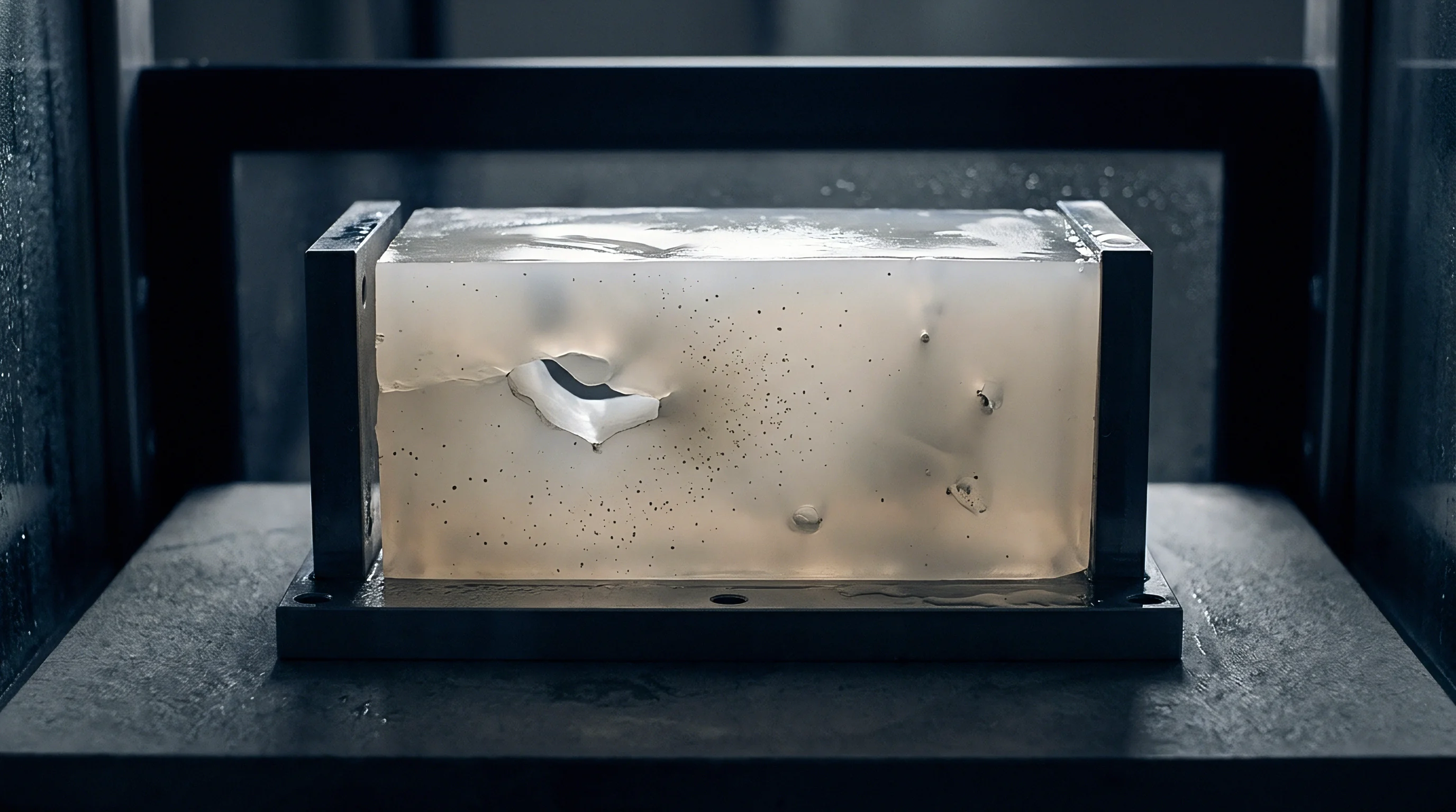
Compliance
Polymer melt behaviour under high hydrostatic packing stress deviates significantly from atmospheric rheological models. High hydrostatic pressure compresses the free volume between macromolecular chains, shifting the glass transition temperature Tg upward by fifteen to twenty-five kelvin per thousand bar of packing pressure. This pressure-induced glass transition causes the polymer boundary layer to vitrify earlier in the moulding cycle than predicted by ambient cooling curves.
Viscoelastic deformation of this vitrified skin against steel micro-asperities relies on time-dependent compliance. Elastic compliance dominates the initial elastic response during the pressure spike at switchover. Viscoelastic creep compliance governs the subsequent penetration of the polymer into steel micro-valleys during the holding phase.
Hydrostatic pressure modifies the relaxation spectrum, slowing down molecular motion and extending stress relaxation times by several orders of magnitude.
Time-temperature-pressure superposition models extend the standard Williams-Landel-Ferry equation by introducing a pressure shift factor C3. Increased hydrostatic pressure scales the effective viscosity upward, resisting shear flow while increasing bulk compressive resistance. As the polymer skin cools under pressure, time-dependent compliance drops, locking the deformed micro-shape into the semi-crystalline or amorphous part boundary.

Mathematical Formulation of Micro-Asperity Penetration Depth
Determining the physical penetration depth of a polymer skin into a metallic tool valley requires coupling bulk viscoelastic compliance with surface contact mechanics. The Greenwood-Tripp elastoplastic contact model assumes spherical metallic micro-asperities contacting a deformable viscoelastic continuum. Total contact deformation combines immediate elastic response and delayed creep response under constant packing pressure.
The total micro-penetration depth h as a function of holding time t under hydrostatic pressure P is expressed as:
h(t) = ( (3 P R_asp) / (4 E_eff(t, P)) )^(2/3)
Where R_asp represents the mean radius of curvature of the tool micro-asperities, and E_eff(t, P) represents the effective pressure-dependent relaxation modulus of the polymer boundary skin layer. The effective relaxation modulus accounts for pressure-shifted vitrification through the modified bulk modulus K(P) and shear modulus G(t, P):
E_eff(t, P) = (9 K(P) G(t, P)) / (3 K(P) + G(t, P))
At twelve hundred bar hydrostatic packing pressure, semi-crystalline polybutylene terephthalate penetrates steel micro-valleys to seventy-eight percent of peak roughness depth within three seconds of switchover.
Consider a practical processing scenario. A moulding press processes a thirty percent glass-filled polybutylene terephthalate housing using a tool steel insert with a mean micro-asperity peak radius of four micrometres and a peak roughness depth Rz of two point five micrometres. The process settings apply a peak cavity packing pressure of twelve hundred bar held for twelve seconds.
Melt temperature enters the cavity at two hundred and sixty degrees Celsius, while tool coolant holds the steel wall at eighty degrees Celsius.
At switchover, hydrostatic pressure jumps from eighty bar filling resistance to twelve hundred bar packing pressure in forty milliseconds. Free volume drops immediately by three point eight percent. The effective glass transition temperature of the skin layer jumps from sixty-six degrees Celsius to ninety-one degrees Celsius, causing instantaneous vitrification of a twelve-micrometre boundary skin.
The initial elastic compliance allows an immediate indentation depth of zero point forty-two micrometres into the steel micro-grooves.
During the subsequent twelve-second packing phase, viscoelastic creep continues under high pressure. Between zero and three seconds, the relaxation modulus drops from two point eight gigapascals to one point one gigapascals, driving additional creep penetration to one point ninety-five micrometres. Between three and twelve seconds, temperature drop increases the shear modulus faster than pressure relaxation lowers it, arresting further penetration at two point zero five micrometres.
Final mechanical interlocking encompasses eighty-two percent of total steel roughness depth.
Pressure compresses the free volume. Hydrostatic stress shifts relaxation spectra.
Unresolved boundary effects persist across the melt front. Modeling transient viscoelastic recovery during the rapid pressure decay at gate seal remains an active domain of rheological research.


Drag
Interlocking between polymer skins and steel micro-asperities creates severe mechanical drag during part ejection. As the polymer cools inside the mould, volumetric thermal shrinkage pulls the part wall away from cavity surfaces. Core features experience the opposite effect: thermal contraction wraps the cooling polymer shell tightly around metallic cores, driving residual contact stresses up to three hundred bar prior to mould opening.
Static friction coefficients measured under laboratory sliding conditions fail to predict core stripping forces. Real ejection behavior depends on the dynamic decay of micro-interlocking keys formed during the high-pressure packing phase. When the ejection hydraulic circuit actuates ejection pins, the solid polymer skin must deform shear-wise over the metallic asperities that it encapsulated during packing.
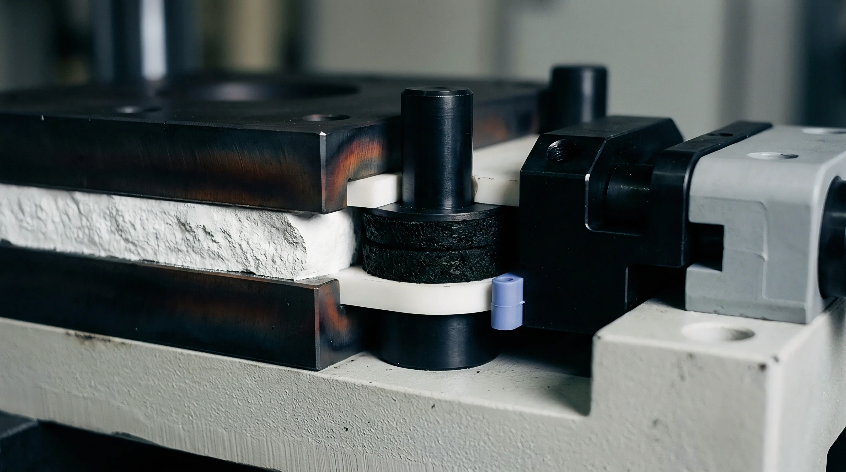
How Does Micro Interlocking Elevate Ejection Force Dynamics?
Actuation of ejection mechanisms forces polymer micro-keys through sharp convergence zones defined by steel topography. Initial pin movement requires overcoming static chemical adhesion and mechanical shear strength of the interlocked polymer peaks. Once motion initiates, friction converts from static resistance to dynamic sliding drag, generating localized frictional heating at the boundary.
High mechanical drag causes optical scuffing, stress whitening, and catastrophic wall punch-through. Part wall deformation occurs when local pin ejection pressure exceeds the compressive yield strength of the warm polymer wall. Standard tool designs attempt to overcome ejection drag by increasing draft angles, but micro-asperity interlocking can override draft clearances up to two degrees if surface finishing remains transverse to the draw direction.
| Polymer Matrix | Tool Surface Roughness Rz (µm) | Draft Angle (degrees) | Peak Ejection Force (kN) | Thermal Contact Conductance (W/m²K) |
|---|---|---|---|---|
| Unfilled PBT | 0.4 | 0.5 | 3.2 | 2200 |
| Unfilled PBT | 2.1 | 0.5 | 8.7 | 1350 |
| PA66 GF30 | 0.4 | 0.5 | 5.8 | 2600 |
| PA66 GF30 | 2.1 | 0.5 | 14.1 | 1600 |
| PA66 GF30 | 2.1 | 1.5 | 6.4 | 1580 |
Thermal contact conductance drops sharply as the part shrinks away from cavity walls, but core surfaces maintain contact throughout cooling. Heat flux across core interfaces remains high until ejection pin movement breaks physical contact. Dynamic changes in thermal conductance directly influence cooling uniformity and final part warpage.
Friction spikes during core collapse. Polished tool surfaces reduce mechanical keying. Static friction exceeds dynamic drag.
- Stress Whitening occurs when localized boundary tensile shear stresses exceed the crazing threshold of amorphous polymers during core stripping.
- Pin Delamination happens when concentrated pin forces punch through warm inner wall sections due to excessive boundary frictional drag.
- Core Seizure results from differential thermal shrinkage locking glass-filled polymers onto rough textured cores lacking sufficient draft angle.
- Thermal Streak Scoring surfaces when dynamic friction generates localized frictional heating above the melt temperature during ejection.
Under DIN 16742 Group 140 specifications, demoulding force calculations must account for surface roughness keying factors when packing pressure exceeds eight hundred bar.
Selecting incorrect cavity finishing processes yields permanent part distortion, raised wall scrap rates, and damaged core steel.
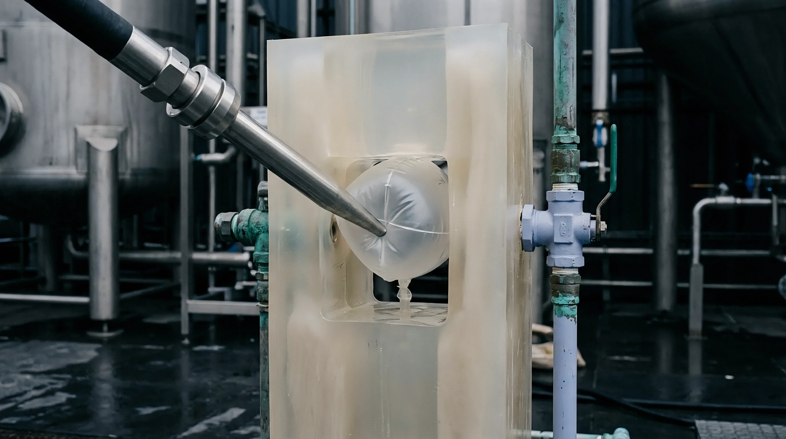
Gauge
Verifying micro-asperity viscoelastic deformation requires precise inline and off-line measurement tools. Cavity pressure transducers installed directly behind core steel faces capture the true hydrostatic stress profile during pack and hold phases. Piezoelectric quartz sensors sample cavity pressure at rates up to two kilohertz, mapping exact switchover timing and pressure decay curves.
Off-line verification of boundary replication uses optical white-light interferometry and 3D laser confocal profilometry. Comparing original tool steel surface topographies against ejected polymer part surface replicas reveals the true boundary replication fidelity. High-fidelity contact replication indicates complete viscoelastic creep into steel micro-valleys during the packing window.
Ultrasonic boundary monitoring systems provide real-time non-destructive insight into the polymer-steel contact area fraction during the moulding cycle. High-frequency ultrasonic waves transmitted through cavity steel reflect off the polymer boundary. Amplitude decay of reflected ultrasonic pulses corresponds directly to acoustic impedance matching, providing a continuous quantitative measurement of contact area growth during high packing stress.
The boundary measurement sequence follows a strict operational path across tool trials:
- Mount Piezoelectric Transducers flush within cavity walls to record real-time hydrostatic pressure profiles during pack and hold phases.
- Measure Unloaded Tool Topography using 3D laser confocal profilometry to establish baseline Ra, Rz, Rsk, and Rku metrics across all core features.
- Record Ultrasonic Impedance during process bring-up to monitor boundary contact area fraction growth across pack pressure sweeps.
- Map Polymer Surface Replicas off-line using white-light interferometry to quantify micro-asperity replication depth as a function of holding time.
Standardized tolerance systems define allowable geometric deviations for moulded components. ISO 294 governs injection moulding specimen preparation conditions, ensuring consistent thermal history and packing profiles during test specimen production. DIN 16742 classifies moulding tolerances based on polymer shrinkage variance and tool steel precision grade.
Gate seal stops mass transfer. Cavity pressure decays exponentially. Ejection pins push against residual stress.
According to DIN 16742 Clause 5.2, dimensional compliance claims for precision mouldings produced under hydrostatic packing stresses above one thousand bar require full documentation of cavity pressure trace stability across a minimum fifty-shot continuous production series.
Capital
Tooling capital commitments depend directly on surface texturing choices, steel grade selections, and cycle time targets. High-volume moulding programs amortize tool steel costs across millions of production units, making cycle time reductions of tenths of a second economically decisive. Micro-asperity boundary optimization reduces cooling cycle duration by maximizing thermal contact conductance during the pack phase.
Selecting premium tool steels such as chromium-alloyed 1.2083 or powder-metallurgy CPM S30V increases initial tool fabrication quotes by fifteen to twenty-five percent compared to standard 1.2311 steel. Hardened corrosion-resistant steel maintains polished micro-topography across millions of high-pressure packing cycles without micro-abrasion wear. Soft tool steel wears rapidly under high hydrostatic packing of glass-filled resins, degrading surface finish and escalating ejection friction over time.
| Steel Material Grade | Hardness (HRC) | Surface Finishing Specification | Tooling Cost Multiplier | Target Tool Life (Shots) |
|---|---|---|---|---|
| 1.2311 (P20) | 32 | SPI B2 Paper Finish | 1.00 | 300,000 |
| 1.2343 (H13) | 52 | SPI A2 Optical Polish | 1.35 | 1,000,000 |
| 1.2083 (420 SS) | 54 | SPI A1 Diamond Polish | 1.55 | 2,000,000 |
| CPM S30V PM | 60 | Laser Micro-Textured | 2.10 | 5,000,000 |
Laser surface micro-texturing adds substantial initial tooling expense but creates targeted micro-dimple patterns with controlled negative skewness. These micro-dimples minimize dynamic ejection friction while maintaining high thermal contact area during the packing phase. Lower ejection friction permits smaller ejection pins, reducing cosmetic mark sizes on visible product faces.
Tooling amortisation models evaluate piece-price savings generated by faster heat extraction against the upfront capital cost of diamond polishing or laser texturing. Higher thermal contact conductance shortens hold times, dropping cycle time by up to eight percent on thick-walled structural housings. Over a two-million-unit production contract, a zero point six second cycle time reduction offsets the upfront cost of premium tool steel and SPI A1 polishing within the first six months of commercial production.
Cooling rate dictates crystalline density. Polished tool surfaces reduce mechanical keying.
Tooling suppliers often state that surface finishing touch-ups can be performed late in the bench trial phase without affecting cavitation dimensions or cycle time commitments.